check oil RENAULT TWINGO RS 2009 2.G Engine And Peripherals Service Manual
[x] Cancel search | Manufacturer: RENAULT, Model Year: 2009, Model line: TWINGO RS, Model: RENAULT TWINGO RS 2009 2.GPages: 652
Page 354 of 652
13A-11
FUEL SUPPLY
Fuel pressure: Check
D4F or D7F
13A
aConnect:
-the pipe fitted with a pressure checking gauge with
the “T” union of the tool (Mot. 1311-08),
-the “T” union to the rail,
-the petrol inlet duct to the “T” union.
aStart the engine.
aDetermine the pressure:
-the pressure must be a constant 3.5 bar,
-It may take a few seconds to obtain a correct injec-
tor rail pressure reading.
aSwitch off the engine.
III - FINAL OPERATION
aRemove the “T” union (Mot. 1311-08).
aRemove:
-the oil filler neck,-the “T” union (Mot. 1311-08).
aConnect the fuel supply union.
aRefit the oil filler neck. D7F
121822
D7F
D4F
D4F
Page 357 of 652
13A-14
FUEL SUPPLY
Fuel flow: Check
D4F or D7F
13A
CHECK
a
I - PREPARATION OPERATION FOR CHECK
aRemove the oil filler neck.
aDisconnect the fuel supply union.aFit a “T” union to the fuel supply union (Mot. 1311-
08).
aFit a pipe which is long enough to drain the pump
into a container to the “T” outlet union. Special tooling required
Mot. 1311-08Union for taking fuel pres-
sure measurements .
Equipment required
graduated measuring cylinder
IMPORTANT
During this operation, be sure to:
-refrain from smoking or bringing red hot objects
close to the working area,
-be careful of fuel splashes when disconnecting
the union.
IMPORTANT
Wear goggles with side protectors for this opera-
tion.
IMPORTANT
Wear leaktight gloves (Nitrile type) for this opera-
tion.
WARNING
To avoid any corrosion or damage, protect the
areas on which fuel is likely to run.
D4F
D4F, and 772
121778
Page 359 of 652
13A-16
FUEL SUPPLY
Fuel flow: Check
D4F or D7F
13A
aRemove the relay (1) .
aShunt the relay to supply the electric fuel pump.
III - FINAL OPERATION
aRefit:
-the fuel pump relay,
-the cover of the engine compartment connection
unit.
aRemove the “T” union (Mot. 1311-08).
aConnect the fuel supply union.
aRefit the oil filler neck.
119373
Note:
The flow reading should be 80 to 120 l/h.
D4F
Page 363 of 652
13B-2
DIESEL INJECTION
Diesel injection: Precautions for the repair
K9K
13B
II - ADVICE TO BE FOLLOWED BEFORE ANY
OPERATION
1) Carry out the work in a clean working area and take
care to protect removed components from dust using
plastic bags which are hermetically-resealable, for ex-
ample.
2) Always order the following from the Parts Depart-
ment before carrying out work:
-a new set of blanking plugs, specific to the engine,
-enough lint-free cleaning cloths.
-one of the two cleaning products for fuel pipe
unions,
-the parts that are always to be replaced after each
removal operation, mentioned in the operational pro-
cedures specific to the vehicle (see related Workshop
Repair Manual).
3) Wear safety goggles fitted with side shields to pre-
vent the cleaning product from splashing the eyes.
4) Wear leaktight protective gloves (Nitrile type) to
avoid prolonged contact with the skin.
5) Before carrying out work on the injection system,
use plastic bags or clean rags, for example, to protect:
-the accessories and timing belts,
-the electrical accessories (starter, alternator, power-
assisted steering pump, sensors and electrical con-
nectors),
-the flywheel face.
III - INSTRUCTIONS TO BE FOLLOWED DURING
THE OPERATION
Wash your hands before and while carrying out the
work.
Replace leaktight protective gloves (Nitrile type) when
they are soiled or damaged.
All components removed from the injection system
must be stored in a hermetically sealed plastic bag
once they have been capped.
Reseal the bag hermetically, for example using adhe-
sive tape, even if the bag must be opened shortly after-
wards: ambient air can be a source of impurities.After opening the fuel circuit, the use of brushes, clean-
ing agents, air blow guns, rifle-type brushes or stan-
dard cloths is strictly prohibited: these items are likely
to allow impurities to enter the system.
When replacing a component with a new one or when
refitting it after storing it in a plastic bag, do not unpack
it until it is time to fit it on the vehicle.
IV - CLEANING
There are currently two procedures for cleaning the
fuel circuit before opening it in order to carry out work in
the workshop.
These procedures enable the fuel circuit to be cleaned
to prevent contamination from entering: they both have
the same end result and neither is preferred over the
other.
1 - Cleaning using injector cleaner
Clear the access to the unions that need opening, fol-
lowing the work procedures specific to the vehicle (see
the relevant Workshop Repair Manual).
Protect sections which are sensitive to fuel leaks.
Pour the injector cleaning agent into a container which
is free from impurities.
Dip a clean brush, which is not shedding bristles, into
the container of injector cleaning agent.
Clean the unions carefully using the brush and the in-
jector cleaning agent.
Blast the components that have been cleaned with
compressed air (tools, workbench, and also parts,
unions and around the injection system). Check that no
bristles from the brush have come away and that the
area is clean.
Wipe the sections that were cleaned with fresh clean-
ing cloths.
Open the circuit at the unions and immediately fit the
relevant blanking plugs. Note:
When using leather protective gloves, wear a pair of
leaktight protective gloves (Nitrile type) over the top.
IMPORTANT
Wear leaktight gloves (Nitrile type) for this opera-
tion.
IMPORTANT
Wear goggles with side protectors for this opera-
tion.
Page 385 of 652
13B-24
DIESEL INJECTION
High pressure pump: Removal - Refitting
K9K
13B
aRefit the lower timing cover.
aRefit the accessories belt (see 11A, Top and front
of engine, Accessories belt: Removal - Refitting,
page 11A-3)
aRefit:
-the upper timing cover,
-the camshaft position sensor (see 13B, Diesel in-
jection, Camshaft position sensor: Removal -
Refitting, page 13B-14) ,
-the right-hand suspended engine mounting (see
19D, Engine mounting, Right-hand suspended
engine mounting: Removal - Refitting, page
19D-13) .
aRemove the blanking plugs.
aRefit a high pressure pipe between the pump and
the rail (see 13B, Diesel injection, High pressure
pipe between pump and rail: Removal - Refitting,
page 13B-35) .
aConnect the diesel return pipe to the venturi fitted to
the high pressure pump.aRefit:
-the fuel filter mounting,
-the fuel filter (see 13A, Fuel supply, Fuel filter:
Removal - Refitting, page 13A-4) .
aRefit:
-the engine tie-bar (see 19D, Engine mounting,
Lower engine tie-bar: Removal - Refitting, page
19D-18) ,
-the engine harness channel.
aFit the engine wiring on the engine wiring channel.
aClip on the engine wiring channel.
aConnect to the high pressure pump:
-the diesel supply pipe,
-the diesel return pipe to the diesel filter.
aClip on the high pressure pump pipes.
aRemove the protection on the alternator to prevent
fuel flowing out.
aConnect the connectors of:
-the diesel temperature sensor,
-the flow actuator,
-the injectors,
-the heater plugs.
aRemove the blanking cover which protects the oil
level dipstick guide inlet opening on the cylinder
block.
aRefit:
-the dipstick guide,
-the dipstick,
-the scoop under the scuttle panel grille (see Scoop
under the scuttle panel grille: Removal - Refit-
ting) (56A, Exterior equipment),
-the scuttle panel grille (see Scuttle panel grille:
Removal - Refitting) (56A, Exterior equipment),
-the windscreen wiper arms (see Windscreen wip-
er arm: Removal - Refitting) (85A, Wiping -
Washing).
aPrime the fuel circuit with a manual priming pump
until the disconnected pipes are filled with fuel; if
necessary, bleed the fuel filter (see 13A, Fuel sup-
ply, Fuel filter: Removal - Refitting, page 13A-4) .
aCheck that there are no fuel leaks.
aConnect the battery (see ) (80A, Battery). K9K, and 740
19659
Note:
Make sure that the tab (23) is positioned oppo-
site the mark (24) .
Page 391 of 652
13B-30
DIESEL INJECTION
Flow actuator: Removal - Refitting
K9K
13B
aFit the high pressure pump pipes.
aConnect to the high pressure pump:
-the diesel fuel supply pipe,
-the diesel return pipe.
aAttach the high pressure pump pipes.
aRemove the protection on the alternator to prevent
fuel flowing out.
aConnect the connectors:
-the heater plugs,
-the injectors,
-the flow actuator,
-diesel fuel temperature sensor.
aRemove the blanking cover protecting the dipstick
guide inlet orifice on the cylinder block.
aRefit:
-the dipstick guide,
-the dipstick guide nut,
-the oil level dipstick.
aRefit the neck nuts.
aPrime the fuel circuit with a manual priming pump
until the disconnected pipes are filled with fuel; if
necessary, bleed the fuel filter (see 13A, Fuel sup-
ply, Fuel filter: Removal - Refitting, page 13A-4) .
aConnect the battery (see ) (MR 411, 80A, Battery).
aCheck that there are no fuel leaks.
aCheck the high pressure circuit (see 13B, Diesel in-
jection, High pressure pipe: Check, page 13B-34)
.
aUse the Diagnostic tool to check for an absence of
stored faults; deal with these and clear them as nec-
essary.
aRefit the engine cover.
Page 403 of 652
13B-42
DIESEL INJECTION
High pressure pipe between rail and injector: Removal - Refitting
K9K
13B
aFit and lock a new clip between the high pressure
pipes between the rail and the injectors.
aUsing the (Mot. 1746), tighten to torque:
-the high pressure pipe unions between the
pump and the yellow rail (24 Nm),
-the high pressure pipe unions between the
pump and the silver rail (28 Nm).
III - FINAL OPERATION.
aRefit:
-the channel,
-the neck nut.
aFit the neck wiring harness.
aClip the neck on.
aConnect to the high pressure pump:
-the diesel fuel supply pipe,
-the diesel return pipe to the diesel filter.
aRemove the protection on the alternator and starter.
aConnect the connectors:
-the heater plugs,
-the injectors,
-the flow actuator,
-diesel fuel temperature sensor.
aRemove the blanking cover protecting the dipstick
guide inlet orifice on the cylinder block.
aRefit:
-the dipstick guide,
-the dipstick guide nut,
-the oil level dipstick.
aRefit the neck nuts.
aPrime the fuel circuit with a manual priming pump
until the disconnected pipes are filled with fuel; if
necessary, bleed the fuel filter (see 13A, Fuel sup-
ply, Fuel filter: Removal - Refitting, page 13A-4) .
aCheck that there are no fuel leaks.
aConnect the battery (see ) (MR 411, 80A, Battery).
aCheck the high pressure circuit (see 13B, Diesel in-
jection, High pressure pipe: Check, page 13B-34)
.
aUse the Diagnostic tool to check for an absence of
stored faults; deal with these and clear them as nec-
essary.
aRefit the engine cover.
Page 408 of 652
13B-47
DIESEL INJECTION
Injector rail: Removal - Refitting
K9K
13B
aRemove the blanking plugs.
aFit the injector rail.
aFit the injector rail nuts without tightening them.
III - FINAL OPERATION.
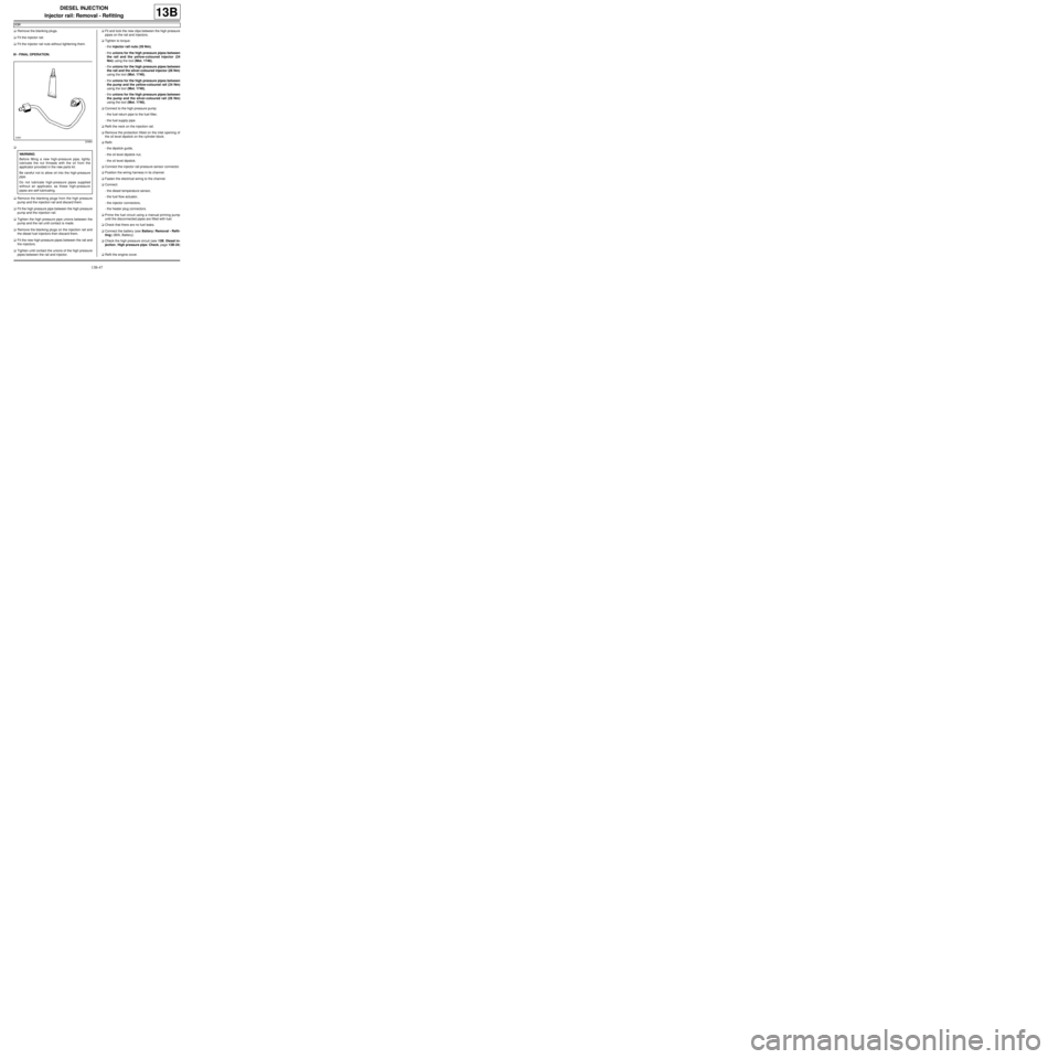
a
aRemove the blanking plugs from the high pressure
pump and the injection rail and discard them.
aFit the high pressure pipe between the high pressure
pump and the injection rail.
aTighten the high pressure pipe unions between the
pump and the rail until contact is made.
aRemove the blanking plugs on the injection rail and
the diesel fuel injectors then discard them.
aFit the new high-pressure pipes between the rail and
the injectors.
aTighten until contact the unions of the high pressure
pipes between the rail and injector.aFit and lock the new clips between the high pressure
pipes on the rail and injectors.
aTighten to torque:
-the injector rail nuts (28 Nm),
-the unions for the high pressure pipes between
the rail and the yellow-coloured injector (24
Nm) using the tool (Mot. 1746),
-the unions for the high pressure pipes between
the rail and the silver-coloured injector (28 Nm)
using the tool (Mot. 1746),
-the unions for the high pressure pipes between
the pump and the yellow-coloured rail (24 Nm)
using the tool (Mot. 1746),
-the unions for the high pressure pipes between
the pump and the silver-coloured rail (28 Nm)
using the tool (Mot. 1746),
aConnect to the high pressure pump:
-the fuel return pipe to the fuel filter,
-the fuel supply pipe.
aRefit the neck on the injection rail.
aRemove the protection fitted on the inlet opening of
the oil level dipstick on the cylinder block.
aRefit:
-the dipstick guide,
-the oil level dipstick nut,
-the oil level dipstick.
aConnect the injector rail pressure sensor connector.
aPosition the wiring harness in its channel.
aFasten the electrical wiring to the channel.
aConnect:
-the diesel temperature sensor,
-the fuel flow actuator,
-the injector connectors,
-the heater plug connectors.
aPrime the fuel circuit using a manual priming pump
until the disconnected pipes are filled with fuel.
aCheck that there are no fuel leaks.
aConnect the battery (see Battery: Removal - Refit-
ting) (80A, Battery).
aCheck the high pressure circuit (see 13B, Diesel in-
jection, High pressure pipe: Check, page 13B-34)
.
aRefit the engine cover.
20960
WARNING
Before fitting a new high-pressure pipe, lightly
lubricate the nut threads with the oil from the
applicator provided in the new parts kit.
Be careful not to allow oil into the high-pressure
pipe.
Do not lubricate high-pressure pipes supplied
without an applicator, as these high-pressure
pipes are self-lubricating.
Page 419 of 652
14A-1
ANTIPOLLUTION
Oil vapour rebreathing circuit: Descriptions
K9K
14A
I - PRESENTATION OF THE CIRCUIT
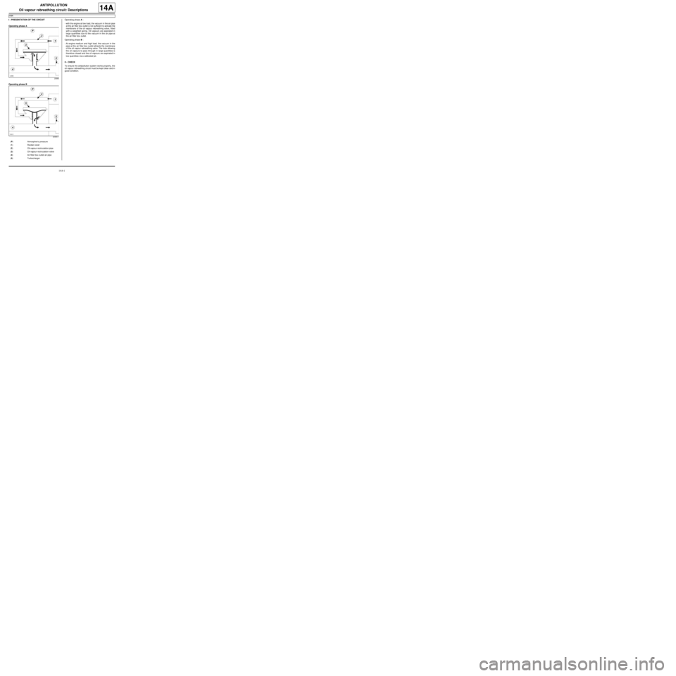
Operating phase A
Operating phase BOperating phase A :
-with the engine at low load, the vacuum in the air pipe
at the air filter box outlet is not sufficient to activate the
membrane of the oil vapour rebreathing valve, fitted
with a weighted spring. Oil vapours are aspirated in
large quantities due to the vacuum in the air pipe at
the air filter box outlet.
Operating phase B :
-At engine medium and high load, the vacuum in the
pipe at the air filter box outlet attracts the membrane
of the oil vapour rebreathing valve. The hole allowing
the oil vapours to pass through in large quantities is
therefore closed and the oil vapours are aspirated in
low quantities via a calibrated jet.
II - CHECK
To ensure the antipollution system works properly, the
oil vapour rebreathing circuit must be kept clean and in
good condition.
20965
20965-1
(P) Atmospher ic pressure
(1) Rocker cover
(2) Oil vapour recirculation pipe
(3) Oil vapour recirculation valve
(4) Air filter box outlet air pipe
(5) Turbocharger
Page 464 of 652
17A-8
IGNITION
Coils: Removal - Refitting
D4F, and 780 or 782
17A
REFITTING
I - REFITTING PREPARATION OPERATION
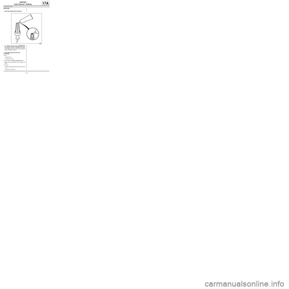
aIt is essential to apply a bead of FLUOSTAR 2L
(see Vehicle: Parts and consumables for the re-
pair) (04B, Consumables - Products) with a diame-
ter of 2 mm to the inner edge of the high-tension
caps on the ignition coil side.
II - REFITTING OPERATION FOR PART
CONCERNED
aRefit:
-the ignition coil,
-the ignition coil bolts.
aTorque tighten the ignition coil bolts (10 N.m).
aCheck the spark plug leads and the ignition coil
match.
aConnect:
-the spark plug lead high-tension caps to the ignition
coil,
-the ignition coil connector.
106640