ESP RENAULT TWINGO RS 2009 2.G Engine And Peripherals Workshop Manual
[x] Cancel search | Manufacturer: RENAULT, Model Year: 2009, Model line: TWINGO RS, Model: RENAULT TWINGO RS 2009 2.GPages: 652
Page 488 of 652
17B-13
PETROL INJECTION
Oxygen sensors: Removal - Refitting
D4F, and 772 – D7F
17B
REMOVAL
I - REMOVAL PREPARATION OPERATION
aPosition the vehicle on a two-post lift (see Vehicle:
Towing and lifting) (02A, Lifting equipment).II - REMOVING THE UPSTREAM OXYGEN SENSOR
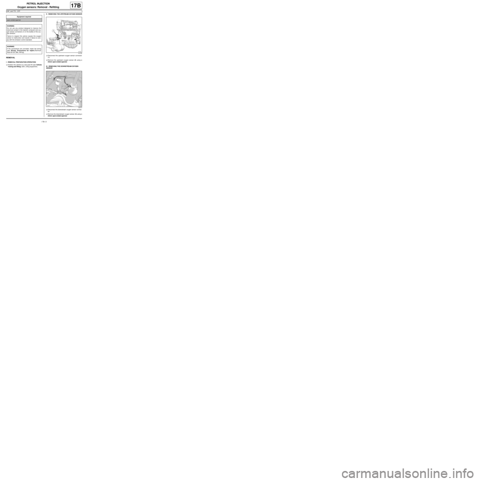
aDisconnect the upstream oxygen sensor connector
(1) .
aRemove the upstream oxygen sensor (2) using a
24mm open-ended spanner.
III - REMOVING THE DOWNSTREAM OXYGEN
SENSOR
aDisconnect the downstream oxygen sensor connec-
tor.
aRemove the downstream oxygen sensor (3) using a
24mm open-ended spanner. Equipment required
open-ended spanner
WARNING
Do not use any product designed to improve the
electr ical contact in the injection computer and oxy-
gen sensor connectors or on the bodies of the oxy-
gen sensors.
Failure to respect this advice causes the oxygen
sensor to malfunction and results in failure to com-
ply with the emission control standard.
WARNING
If the connections are corroded, repair the wiring
(see Wiring: Precautions for repair)(Technical
Note 6015A, 88A, Wiring).
121732
120415
Page 490 of 652
17B-15
PETROL INJECTION
Oxygen sensors: Removal - Refitting
D4F, and 780 or 782
17B
REMOVAL
I - REMOVAL PREPARATION OPERATION
aPosition the vehicle on a two-post lift (see Vehicle:
Towing and lifting) (02A, Lifting equipment).
II - OPERATION FOR REMOVAL OF PART
CONCERNED
1 - Removing the upstream oxygen sensor
aRemove the air filter unit (see 12A, Fuel mixture,
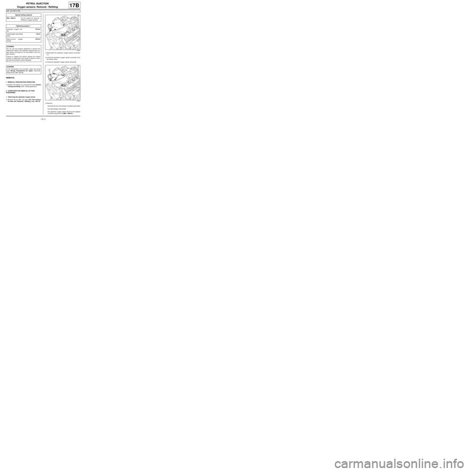
Air filter unit: Removal - Refitting, page 12A-13) .aDisconnect the upstream oxygen sensor connector
(1) .
aUnclip the upstream oxygen sensor connector from
the rocker cover.
aUnclip the upstream oxygen sensor wiring (2) .
aRemove:
-the bolts (3) from the exhaust manifold heat shield,
-the turbocharger heat shield,
-the upstream oxygen sensor (4) from the catalytic
converter using the tool (Mot. 1495-01). Special tooling required
Mot. 1495-0122 mm socket for removal -
refitting of oxygen sensors.
Tightening torquesm
upstream oxygen sen-
sor45 N.m
turbocharger heat shield
bolts8 N.m
downstream oxygen
sensor45 N.m
WARNING
Do not use any product designed to improve the
electr ical contact in the injection computer and oxy-
gen sensor connectors or on the bodies of the oxy-
gen sensors.
Failure to respect this advice causes the oxygen
sensor to malfunction and results in failure to com-
ply with the emission control standard.
WARNING
If the connections are corroded, repair the wiring
(see Wiring: Precautions for repair) (Technical
Note 6015A, 88A, Wiring).
120957
120957
Page 492 of 652
17B-17
PETROL INJECTION
Oxygen sensors: Removal - Refitting
K4M
17B
REMOVING THE UPSTREAM OXYGEN
SENSOR
I - REMOVAL PREPARATION OPERATION
aPosition the vehicle on a two-post lift (see Vehicle:
Towing and lifting) (02A, Lifting equipment).
aRemove:
-the front right-hand wheel (see Wheel: Removal -
Refitting) (35A, Wheels and tyres),-the front right-hand wheel arch liner (see Front
wheel arch liner: Removal - Refitting) (55A, Ex-
terior protection),
-the engine undertray.
II - REMOVAL OPERATION
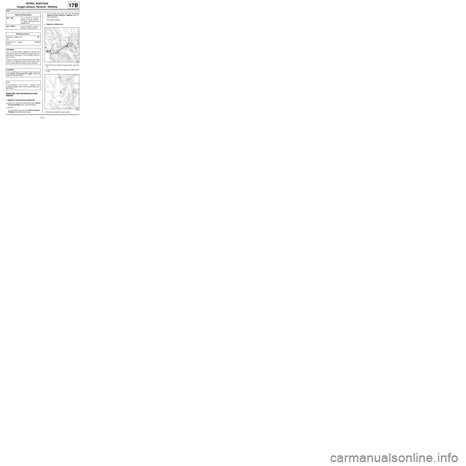
aDisconnect the upstream oxygen sensor connector
(1) .
aUnclip the wiring from the upstream oxygen sensor
at (2) .
aRemove the upstream oxygen sensor . Special tooling required
Mot. 149522 mm socket for removal -
refitting of oxygen sensors -
1/2" square dr ive and 24 mm
hexagonal ext.
Mot. 1495-0122 mm socket for removal -
refitting of oxygen sensors.
Tightening torquesm
upstream oxygen sen-
sor90˚
downstream oxygen
sensor45 N.m
WARNING
Do not use any product designed to improve the
electr ical contact in the injection computer and oxy-
gen sensor connectors or on the bodies of the oxy-
gen sensors.
Failure to respect this advice prevents the oxygen
sensor from operating correctly and results in fail-
ure to comply with the emission control standard.
WARNING
If the connections are corroded, repair the wiring
(see Wiring: Precautions for repair) (Technical
Note 6015A, 88A, Wiring).
Note:
This procedure is for removal - refitting of the
upstream oxygen sensor and the downstream oxy-
gen sensor.
132373
132539
Page 495 of 652
17B-20
PETROL INJECTION
Petrol injection computer: Removal - Refitting
D4F or D7F
17B
REMOVAL
I - REMOVAL PREPARATION OPERATION
aDisconnect the battery (see ) (MR 411, 80A, Bat-
tery).II - OPERATION FOR REMOVAL OF PART
CONCERNED
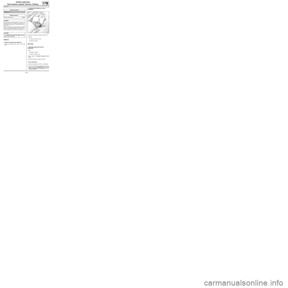
aDisconnect the injection computer connectors (1) .
aRemove:
-the injection computer nuts (2) ,
-the injection computer.
REFITTING
I - REFITTING OPERATION FOR PART
CONCERNED
aRefit:
-the injection computer,
-the injection computer nuts.
aTorque tighten the injection computer nuts (8
N.m).
aConnect the injection computer connectors.
II - FINAL OPERATION
aConnect the battery (see ) (MR 411, 80A, Battery).
aCarry out the necessary configurations and/or pro-
gramming, using the Diagnostic tool (see Fault
finding - Replacement of components) (MR 413,
17B, Petrol injection). Equipment required
Diagnostic tool
Tightening torquesm
injection computer nuts8 N.m
WARNING
Do not use any product designed to improve the
electr ical contact in the injection computer and oxy-
gen sensor connectors or on the bodies of the oxy-
gen sensors.
Failure to respect this advice prevents the oxygen
sensor from operating correctly and results in fail-
ure to comply with the emission control standard.
WARNING
If the connections are corroded, repair the wiring
(see Wiring: Precautions for repair) (Technical
Note 6015A, 88A, Wiring).
120779
Page 496 of 652
17B-21
PETROL INJECTION
Petrol injection computer: Removal - Refitting
K4M
17B
REMOVAL
I - REMOVAL PREPARATION OPERATION
aRemove the battery (see Battery: Removal - Refit-
ting) (80A, Battery).aRemove:
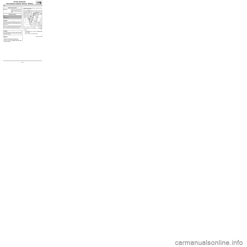
-the tamperproof bolts (1) using the tool (Mot. 1844)
(2) and a drill,
-the petrol injection computer protector. Special tooling required
Mot. 1844Drill bush for removing the
tamper-proof bolts from the
injection computer protective
cover
Equipment required
drill
Diagnostic tool
WARNING
Do not use any product designed to improve the
electr ical contact in the injection computer and oxy-
gen sensor connectors or on the bodies of the oxy-
gen sensors.
Failure to respect this advice prevents the oxygen
sensor from operating correctly and results in fail-
ure to comply with the emission control standard.
WARNING
If the connections are corroded, repair the wiring
(see Wiring: Precautions for repair) (Technical Note
6015A, 88A, Wiring).
RIGHT-HAND DRIVE
132448
Page 630 of 652
19C-16
TANK
Fuel level sensor module: Removal - Refitting
D4F or D7F or K4M or K9K
19C
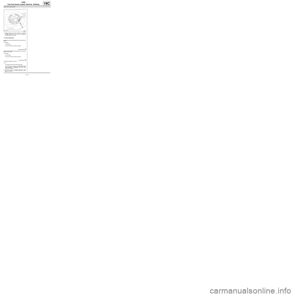
aTighten the fuel level sensor module nut using the
tool (Mot. 1397) until the nut mark (11) corresponds
with the fuel tank mark (12) .
III - FINAL OPERATION
aConnect:
-the fuel pipe,
-the fuel level sensor module connector.
aConnect:
-the fuel pipes,
-the fuel level sensor module connector.
aRefit the inspection flap cover.
aFit:
-the carpet under the rear bench seat base.
-the rear bench seat base (see Rear bench seat
base: Removal - Refitting) (76A, Rear seat
frames and runners).
aConnect the battery (see Battery: Removal - Refit-
ting) (80A, Battery).
102470
K4M
D4F or D7F or K9K