brake pads RENAULT TWINGO RS 2009 2.G Engine And Peripherals Workshop Manual
[x] Cancel search | Manufacturer: RENAULT, Model Year: 2009, Model line: TWINGO RS, Model: RENAULT TWINGO RS 2009 2.GPages: 652
Page 84 of 652

10A-78
ENGINE AND CYLINDER BLOCK ASSEMBLY
Engine - gearbox assembly: Removal - Refitting
D4F or D7F
10A
aDrain the coolant circuit (see Refrigerant circuit:
Draining - Filling) .
aRemove:
-the air conditioning pipe bolts on the compressor,
-the air conditioning pipe bolt on the dehydrator res-
ervoir.
aDisconnect the air conditioning pressostat connec-
tor.
a
aDisconnect the fuel supply pipe union.
aInsert the blanking plugs.
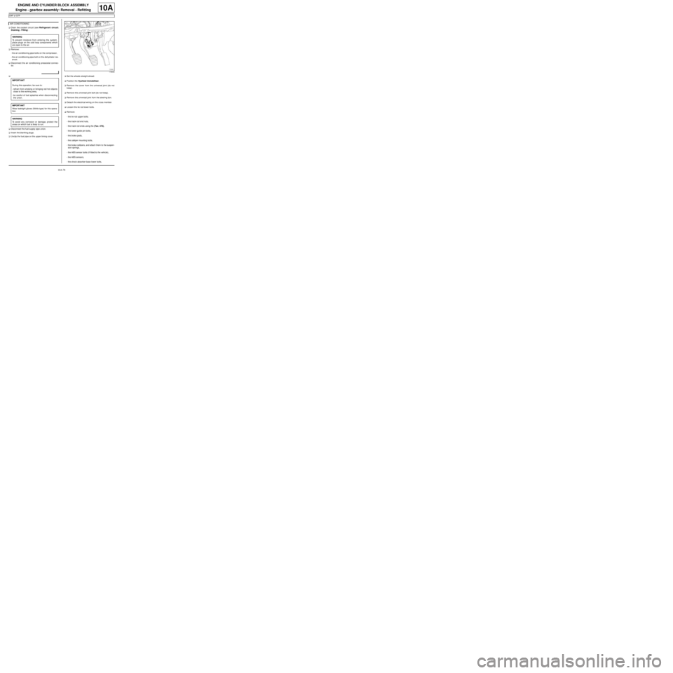
aUnclip the fuel pipe on the upper timing cover.aSet the wheels straight ahead.
aPosition the flywheel immobiliser.
aRemove the cover from the universal joint (do not
keep).
aRemove the universal joint bolt (do not keep).
aRemove the universal joint from the steering box.
aDetach the electrical wiring on the cross member.
aLoosen the tie rod lower bolts.
aRemove:
-the tie rod upper bolts.
-the track rod end nuts,
-the track rod ends using the (Tav. 476),
-the lower guide pin bolts,
-the brake pads,
-the calliper mounting bolts,
-the brake callipers, and attach them to the suspen-
sion springs,
-the ABS sensor bolts (if fitted to the vehicle),
-the ABS sensors,
-the shock absorber base lower bolts, AIR CONDITIONING
WARNING
To prevent moisture from entering the system,
place plugs on the cold loop components which
are open to the air.
IMPORTANT
During this operation, be sure to:
-refrain from smoking or bringing red hot objects
close to the working area,
-be careful of fuel splashes when disconnecting
the union.
IMPORTANT
Wear leaktight gloves (Nitrile type) for this opera-
tion.
WARNING
To avoid any corrosion or damage, protect the
areas on which fuel is likely to run.
119544
Page 89 of 652

10A-83
ENGINE AND CYLINDER BLOCK ASSEMBLY
Engine - gearbox assembly: Removal - Refitting
D4F or D7F
10A
aTorque tighten:
-the front subframe bolts (62 N.m),
-the rear subframe bolts (105 N.m),
-the subframe rear tie rod inner bolts (21 N.m),
-the subframe rear tie rod outer bolts (90 N.m),
-the engine tie-bar bolts on the gearbox (105
N.m),
-the engine tie-bar bolt on the subframe (105
N.m).
aRefit the control cables onto the gearbox.
aRemove the blanking plugs from the openings.
aClip the clutch pipe onto the gearbox.
aConnect the clutch slave cylinder.
aRemove the hose clamp (Ms. 583).
aBleed the clutch circuit (see Clutch circuit: Bleed) .
aRefit the gear control linkage.
aAttach the gear control linkage to:
-the gear lever,
-the control lever on the gearbox.
aRefit:
-the heat shield,
-the heat shield bolts.
aRefit the clutch control cable on the manual gearbox.
aRefit the catalytic converter (see 19B, Exhaust,
Catalytic converter: Removal - Refitting, page
19B-12) .aRefit the exhaust downpipe.
aFit the clip.
aTighten the intermediate pipe clip.
aRefit the exhaust downpipe bolts.
aTorque tighten the exhaust downpipe bolts (9
N.m).
aRefit:
-the shock absorber base lower bolts,
-the ABS sensors,
-the ABS sensor bolts (if fitted to the vehicle),
-the brake callipers,
-the calliper mounting bolts,
-the brake pads,
-the lower guide pin bolts,
-track rod ends,
-the track rod end nuts,
-the tie rod upper bolts.
aTorque tighten:
-the shock absorber base lower bolts (105 N.m ),
-the calliper mounting bolts (105 N.m),
-the lower guide pin bolts (34 N.m),
-the track rod end nuts (37 N.m),
-the tie rod upper bolts (21 N.m),
-the tie rod lower bolts (62 N.m).
aClip the electrical wiring on to the cross member.
aFit the steering box universal joint.
aRefit the universal joint bolt.
aTorque tighten the universal joint (24 N.m).
aRemove the flywheel immobiliser.
aClip the fuel pipe on to the upper timing cover.
aConnect the fuel supply pipe union.
aConnect the air conditioning pressostat connector. JH3
JB1 or JH1
D4F, and 772 – D7F
D4F, and 780 or 782
AIR CONDITIONING