heating RENAULT TWINGO RS 2009 2.G Engine And Peripherals Workshop Manual
[x] Cancel search | Manufacturer: RENAULT, Model Year: 2009, Model line: TWINGO RS, Model: RENAULT TWINGO RS 2009 2.GPages: 652
Page 1 of 652
© Renault s.a.s 2007 "The repair procedures given by the manufacturer in this document are based on the
technical specifications current when it was prepared.
The procedures may be modified as a result of changes introduced by the manufacturer in
the production of the various component units and accessories from which the vehicles are
constructed".All rights reserved by Renault.
Copying or translating, in part or in full, of this document or use of the service part reference
numbering system is forbidden without the prior written authority of Renault.
NOVEMBER 2009 EDITION ANGLAISE
X44
1Engine and peripherals
10AENGINE AND CYLINDER BLOCK ASSEMBLY
11ATOP AND FRONT OF ENGINE
12AFUEL MIXTURE
12BTURBOCHARGING
13AFUEL SUPPLY
13BDIESEL INJECTION
13CPREHEATING
14AANTIPOLLUTION
16ASTARTING - CHARGING
17AIGNITION
17BPETROL INJECTION
Page 5 of 652
Contents
13C PREHEATING
Pre-postheating unit:
Removal - Refitting 13C-1
Heater plugs: Removal -
Refitting 13C-2
14A ANTIPOLLUTION
Oil vapour rebreathing
circuit: Descriptions 14A-1
Fuel vapour recirculation
circuit: Operating diagram 14A-2
Fuel vapour recirculation
circuit: Check 14A-3
Fuel vapour absorber:
Removal - Refitting 14A-4
Fuel vapour absorber: Check 14A-7
Fuel vapour absorber bleed
solenoid valve: Removal -
Refitting 14A-8
Exhaust gas recirculation
solenoid valve: Removal -
Refitting 14A-10
Exhaust gas cooler: Removal
- Refitting 14A-11
Exhaust gas recirculation
assembly: Removal -
Refitting 14A-15
Exhaust gas recirculation
rigid pipe: Removal -
Refitting 14A-19
16A STARTING - CHARGING
Alternator: Removal -
Refitting 16A-1
Star ter: Removal - Refitting 16A-10
Alternator pulley: Removal -
Refitting 16A-1717A IGNITION
Coils: Removal - Refitting 17A-1
Plugs: Removal - Refitting 17A-12
17B PETROL INJECTION
Petrol injection: List and
location of components 17B-1
Oxygen sensors: Removal -
Refitting 17B-13
Petrol injection computer:
Removal - Refitting 17B-20
Pinking sensor: Removal -
Refitting 17B-23
Crankshaft position sensor:
Removal - Refitting 17B-25
Injector rail - Injectors:
Removal - Refitting 17B-27
19A COOLING
Engine cooling system:
Specifications 19A-1
Engine cooling system:
Check 19A-2
Engine cooling circuit: List
and location of components 19A-4
Engine cooling system:
Operating diagram 19A-5
Cooling system: Draining -
Refilling 19A-9
Cooling radiator: Removal -
Refitting 19A-12
Coolant pump: Removal -
Refitting 19A-24
Thermostat: Removal -
Refitting 19A-34
Water chamber: Removal -
Refitting 19A-40
Page 72 of 652
10A-66
ENGINE AND CYLINDER BLOCK ASSEMBLY
Multifunction support: Removal - Refitting
D4F, and 772, and STANDARD HEATING – D7F, and STANDARD HEATING
10A
REMOVAL
I - REMOVAL PREPARATION OPERATION
aDisconnect the battery (see Battery: Removal - Re-
fitting) (80A, Battery).
aRemove:
-the accessories belt (see 11A, Top and front of
engine, Accessories belt: Removal - Refitting,
page 11A-3) ,
-the alternator (see 16A, Starting - Charging, Al-
ternator: Removal - Refitting, page 16A-1) .
II - OPERATION FOR REMOVAL OF PART
CONCERNED
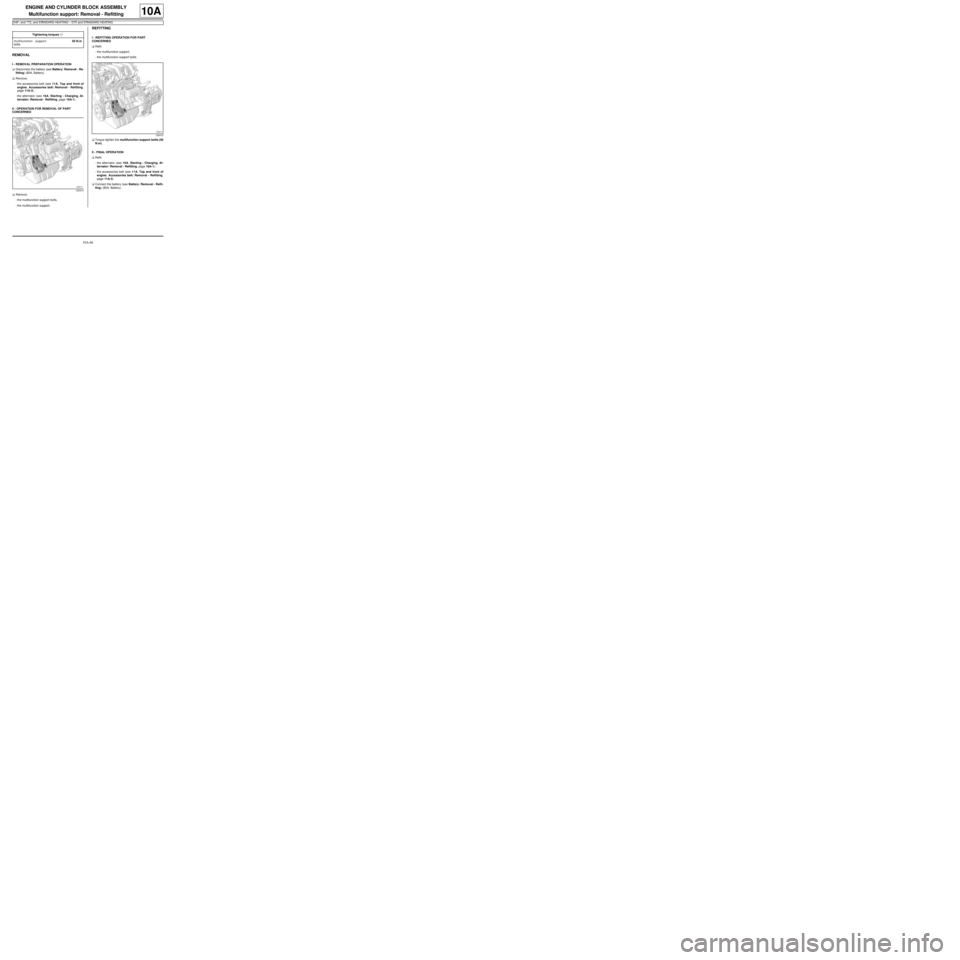
aRemove:
-the multifunction support bolts,
-the multifunction support.
REFITTING
I - REFITTING OPERATION FOR PART
CONCERNED
aRefit:
-the multifunction support,
-the multifunction support bolts.
aTorque tighten the multifunction support bolts (50
N.m).
II - FINAL OPERATION
aRefit:
-the alternator (see 16A, Starting - Charging, Al-
ternator: Removal - Refitting, page 16A-1) ,
-the accessories belt (see 11A, Top and front of
engine, Accessories belt: Removal - Refitting,
page 11A-3) .
aConnect the battery (see Battery: Removal - Refit-
ting) (80A, Battery). Tightening torquesm
multifunction support
bolts50 N.m
120410
120410
Page 74 of 652
10A-68
ENGINE AND CYLINDER BLOCK ASSEMBLY
Multifunction support: Removal - Refitting
K9K, and STANDARD HEATING
10A
The multifunction support is removed when the acces-
sories belt is removed.
REMOVAL
I - REMOVAL PREPARATION OPERATION
aPosition the vehicle on a two-post lift ( (see Vehicle:
Towing and lifting) ).
aDisconnect the battery ( (see Battery: Removal -
Refitting) ).
aRemove:
-the engine cover,
-the front wheels, (see Wheel: Removal - Refit-
ting)
-the front wheel arch liners ( (see Front wheel arch
liner: Removal - Refitting) ),
-the front bumper ( (see Front bumper: Removal -
Refitting) ).
II - OPERATION FOR REMOVAL OF PART
CONCERNED
aRemove the accessories belt (see 11A, Top and
front of engine, Accessories belt: Removal - Re-
fitting, page 11A-3) .
REFITTING
I - REFITTING OPERATION FOR PART
CONCERNED
aRefit the accessories belt (see 11A, Top and front
of engine, Accessories belt: Removal - Refitting,
page 11A-3) .
II - FINAL OPERATION
aRefit:
-the front bumper ( (see Front bumper: Removal -
Refitting) ),
-the front wheel arch liners ( (see Front wheel arch
liner: Removal - Refitting) ),
-the front wheels (see 35A, Wheels and tyres,
Wheels: Removal - Refitting),
-the engine cover.
aConnect the battery ( (see Battery: Removal - Re-
fitting) ).
Page 99 of 652
10A-93
ENGINE AND CYLINDER BLOCK ASSEMBLY
Engine - gearbox assembly: Removal - Refitting
K9K
10A
II - FINAL OPERATION
aRemove the.
aLubricate the seals using recommended air condi-
tioning oil to make fitting easier.
aRefit:
-the connecting pipes to the compressor,
-the connecting pipe union bolts on the compressor,
-the bolt for the connecting pipe mounting on the
compressor.
aConnect:
-the pressostat connector,
-the hose to the coolant pump inlet pipe using the
tool (Mot. 1448).
aFit:
-the hose clip on the coolant pump inlet pipe using
the tool (Mot. 1448),
-the earth on the front left-hand wing.
aRefit the earth nut on the front left-hand wing.
aClip:
-the engine compartment connection unit relay
plates,
-the fuse holders.
aRefit the fuses.
aConnect the preheating unit connector.
aRefit the earth nut on the front left-hand side mem-
ber.
aFit the engine compartment connection unit.
aRefit the engine compartment connection unit
mountings on the body.
aConnect the black connector.
aClip on the black connector.
aRefit:
-the engine compartment connection unit cover,
-a new clip on the battery mounting to hold the elec-
trical wiring.
aConnect the wiring connectors to the fan assembly.aClip the fan assembly wiring.
aRemove the blanking plugs.
aConnect the high pressure pump inlet pipe.
aClip on the fuel supply pipe.
aConnect the high pressure pump return pipe.
aClip on the fuel return pipe.
aRemove the blanking plugs on the clutch hydraulic
control and on the control pipe.
aConnect the clutch hydraulic control to the gearbox.
aClip:
-the clutch control hydraulic pipe on the gearbox,
-the gearbox controls on the cable sleeve stops,
-the gearbox controls on the gear selectors.
aConnect:
-the hoses to the heater radiator,
-the top hose to the water chamber.
aFit:
-the hose clips on the heater radiator using the tool
(Mot. 1448),
-the clip for the top hose on the water chamber us-
ing the tool (Mot. 1448).
aRefit:
-the front section of the intermediate pipe (see 19B,
Exhaust, Intermediate pipe: Removal - Refit-
ting, page 19B-28) ,
-the front right-hand wheel driveshaft (see Front
right-hand driveshaft: Removal - Refitting)
(29A, Driveshafts),
-the front left-hand wheel driveshaft (see Front left-
hand driveshaft: Removal - Refitting) (29A,
Driveshafts),
-the radiator mounting cross member (see Radiator
mounting cross member: Removal - Refitting)
(41A, Front lower structure),
-the front axle subframe (see Front axle subframe:
Removal - Refitting) (31A, Front axle compo-
nents),
-the engine tie-bar (see 19D, Engine mounting,
Lower engine tie-bar: Removal - Refitting, page
19D-18) . WARNING
To prevent any leaks, check that the seal and the
surface of the pipe are in good condition. The
seal and the surface must be clean and scratch
free.
Page 120 of 652
11A-3
TOP AND FRONT OF ENGINE
Accessories belt: Removal - Refitting
D4F, and 772, and STANDARD HEATING – D7F, and STANDARD HEATING
11A
REMOVAL
I - REMOVAL PREPARATION OPERATION
aDisconnect the battery (see Battery: Removal - Re-
fitting) (80A, Battery).
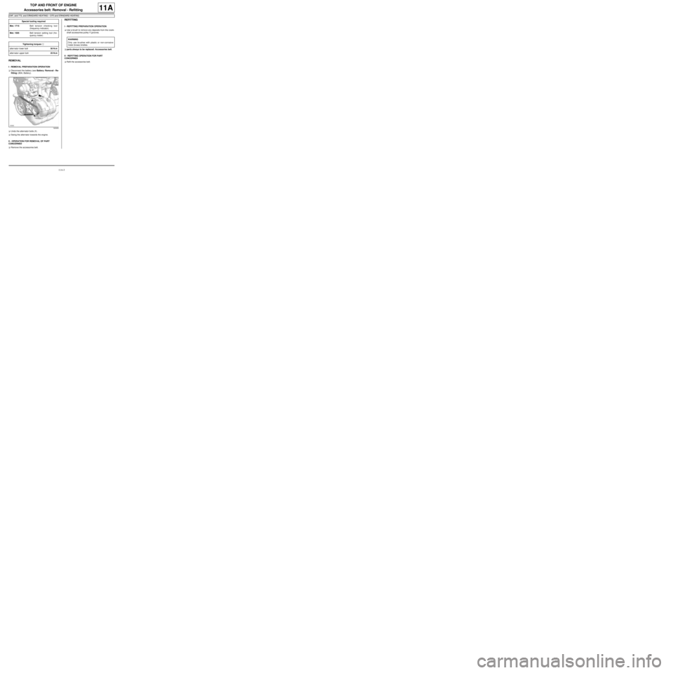
aUndo the alternator bolts (1) .
aSwing the alternator towards the engine.
II - OPERATION FOR REMOVAL OF PART
CONCERNED
aRemove the accessories belt.
REFITTING
I - REFITTING PREPARATION OPERATION
aUse a brush to remove any deposits from the crank-
shaft accessories pulley V grooves.
aparts always to be replaced: Accessories belt.
II - REFITTING OPERATION FOR PART
CONCERNED
aRefit the accessories belt. Special tooling required
Mot. 1715Belt tension checking tool
(frequency indicator).
Mot. 1505Belt tension setting tool (fre-
quency meter)
Tightening torquesm
alter nator lower bolt50 N.m
alter nator upper bolt25 N.m
120305
WARNING
Only use brushes with plastic or non-corrosive
metal (br ass) bristles.
Page 121 of 652
11A-4
TOP AND FRONT OF ENGINE
Accessories belt: Removal - Refitting
D4F, and 772, and STANDARD HEATING – D7F, and STANDARD HEATING
11A
Accessories belt tensioning process
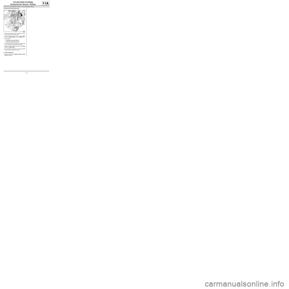
aTension the accessories belt by swinging the alter-
nator towards the front using a lever.
aSet the accessories belt tension using the (Mot.
1715) or the (Mot. 1505) to a value of 244 Hz ±± ± ±
5.
aTorque tighten:
-the alternator lower bolt (50 N.m),
-the alternator upper bolt (25 N.m).
aTurn the engine three revolutions clockwise (timing
end) to position the accessories belt correctly.
aCheck the accessories belt tension using the (Mot.
1715) or the (Mot. 1505).
aIf the accessories belt tension is outside permitted
tolerance values, readjust the tension.
III - FINAL OPERATION
aConnect the battery (see Battery: Removal - Refit-
ting) (80A, Battery).
120525
Page 127 of 652
11A-10
TOP AND FRONT OF ENGINE
Accessories belt: Removal - Refitting
K9K, and STANDARD HEATING
11A
PARTS AND CONSUMABLES FOR THE
REPAIR WORK
aParts always to be replaced:
-accessories belt,
-accessories belt tensioning roller,
-accessories belt tensioning roller bolt
-the air conditioning compressor substitute pulley,
-axle sub-frame bolts.
REMOVAL
I - REMOVAL PREPARATION OPERATION
aPosition the vehicle on a two-post lift (see Vehicle:
Towing and lifting) (MR 411, 02A, Lifting equip-
ment).
aDisconnect the battery (see ) (MR 411, 80A, Bat-
tery).
aRemove:
-the front right-hand wheel (see Wheel: Removal -
Refitting) (MR 411, 35A, Wheels and tyres),
-the front right-hand wheel arch liner (see Front
wheel arch liner: Removal - Refitting) (MR 412,
55A, Exterior protection),
-the front bumper (see Front bumper: Removal -
Refitting) (MR 412, 55A, Exterior protection),
-the left-hand and right-hand headlights (see Halo-
gen headlight: Removal - Refitting) (MR 411,
80B, Headlights).aRemove:
-the air filter inlet air pipe bolt from the front upper
cross member,
-the expansion bottle bolt from the front upper cross
member,
-the cooling radiator retaining bracket bolt from the
front upper cross member.
aUnclip and then remove from the front upper cross
member:
-the air filter inlet air pipe,
-the expansion bottle.
aRemove the bonnet catch bolts.
aRemove the « cable - bonnet catch » assembly.
aRemove the front upper cross member (see Front
upper cross member: Removal - Refitting) (MR
412, 42A, Upper front structure).
II - OPERATION FOR REMOVAL OF PART
CONCERNED
1 - Removing the accessories belt
aRelax the accessories belt using a 16 mm spanner.
aRemove the accessories belt from the air condition-
ing compressor substitute pulley.
aRemove the accessories belt, passing it over its slot
between the RH side member and the crankshaft
accessories and alternator pulleys.
aDiscard the accessories belt
2 - Removing the tensioning roller and the air
conditioning compressor substitute pulley
a
aDisconnect the connector on the alternator.
aRemove the nut from the alternator harness.
aMove the alternator harness to one side.
aRemove the alternator upper bolt.
aLoosen the alternator lower bolt.
aRemove the alternator with its lower bolt fitted. Tightening torquesm
air conditioning com-
pressor substitute pul-
ley bolts25 Nm
tensioning roller bolt40 Nm
bolts mounting the mul-
tifunction support on the
cylinder block44 Nm
bolt mounting the multi-
function support on the
sump25 Nm
alter nator bolts25 Nm
Note:
The tensioning roller and air conditioning com-
pressor substitute pulley must be replaced every
time the accessor ies belt is replaced.
Page 128 of 652
11A-11
TOP AND FRONT OF ENGINE
Accessories belt: Removal - Refitting
K9K, and STANDARD HEATING
11A
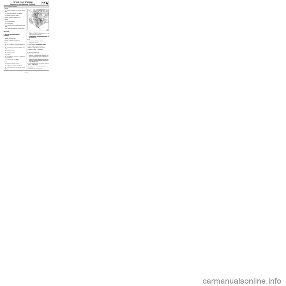
aRemove:
-the multifunction support bolts from the cylinder
block,
-the multifunction support bolt from the sump,
-the equipped multifunction support.
aPlace the multifunction support in a vice.
aRemove:
-the tensioning roller bolt,
-the tensioning roller,
-the air conditioning compressor substitute pulley
bolts,
-the air conditioning compressor substitute pulley.
REFITTING
I - REFITTING OPERATION FOR PART
CONCERNED
1 - Refit the tensioning roller
aPlace the multifunction support in a vice.
aRefit:
-the new air conditioning compressor substitute pul-
ley.
-the air conditioning compressor substitute pulley
bolts,
-the new tensioning roller,
-the tensioning roller bolt,
aTorque tighten:
-the air conditioning compressor substitute pul-
ley bolts (25 Nm),
-the tensioning roller bolt (40 Nm),
aRefit:
-the equipped multifunction support,
-the multifunction support bolt onto the sump,
-the multifunction support bolts onto the cylinder
block.aTighten to torque and in order:
-the bolts mounting the multifunction support
on the cylinder block (44 Nm),
-the bolt mounting the multifunction support on
the sump (25 Nm).
aRefit:
-the alternator with its lower bolt fitted,
-the alternator upper bolt.
aTorque tighten the alternator bolts (25 Nm).
aPosition the alternator wiring harness.
aRefit the nut to the alternator wiring harness.
aAttach the connector to the alternator.
2 - Refit the accessories belt
aPartially refit the new accessories belt:
-positioning it between the air conditioning com-
pressor substitute pulley and the multifunction sup-
port,
-passing it over its slot between the RH side mem-
ber and the crankshaft accessories, tensioning roll-
er and alternator pulleys.
aTurn the accessories belt auto tensioner clockwise
using a 16 mm spanner
aFit the belt on the air conditioning compressor sub-
stitute pulley.
aGently release the tensioning roller.
120315
Page 129 of 652
11A-12
TOP AND FRONT OF ENGINE
Accessories belt: Removal - Refitting
K9K, and STANDARD HEATING
11A
aCheck that the accessories belt is correctly mounted
on the crankshaft accessories, air conditioning com-
pressor and alternator pulleys.
aTurn the engine two revolutions.
aCheck that the accessories belt is correctly fitted on
the crankshaft accessories, air conditioning com-
pressor substitute, alternator and tensioning roller
pulleys.
II - FINAL OPERATION.
aRefit the front upper cross member (see Front up-
per cross member: Removal - Refitting) (MR 412,
42A, Upper front structure).
aFit the « cable - bonnet catch » assembly.
aRefit the bonnet catch nuts.
aClip the following onto the front upper cross mem-
ber:
-the air filter inlet air pipe,
-the expansion bottle.
aRefit:
-the air filter inlet air pipe bolt onto the front upper
cross member,
-the expansion bottle bolt onto the front upper cross
member,
-the cooling radiator retaining bracket bolt onto the
front upper cross member.
-the left-hand and right-hand headlights (see Halo-
gen headlight: Removal - Refitting) (MR 411,
80B, Headlights).
-the front bumper (see Front bumper: Removal -
Refitting) (MR 412, 55A, Exterior protection),
-the front right-hand wheel arch liner (see Front
wheel arch liner: Removal - Refitting) (MR 412,
55A, Exterior protection),
-the front right-hand wheel (see Wheel: Removal -
Refitting) (MR 411, 35A, Wheels and tyres),
aConnect the battery (see ) (MR 411, 80A, Battery).
aAdjust the headlights (see Halogen headlight: Ad-
justment) (MR 411, 80B, Headlights).