oil filter RENAULT TWINGO RS 2009 2.G Engine And Peripherals Workshop Manual
[x] Cancel search | Manufacturer: RENAULT, Model Year: 2009, Model line: TWINGO RS, Model: RENAULT TWINGO RS 2009 2.GPages: 652
Page 9 of 652
10A-3
ENGINE AND CYLINDER BLOCK ASSEMBLY
Crankshaft seal, gearbox end: Removal - Refitting
K4M
10A
REMOVAL
I - REMOVAL PREPARATION OPERATION
aPosition the vehicle on a two-post lift (see Vehicle:
Towing and lifting) (02A, Lifting equipment).
aRemove:
-the engine undertray,
-the battery (see Battery: Removal - Refitting)
(80A, Battery),
-the air filter unit (see 12A, Fuel mixture, Air filter
unit: Removal - Refitting, page 12A-13) ,
-the petrol injection computer (see 17B, Petrol in-
jection, Petrol injection computer: Removal -
Refitting, page 17B-20) ,
-the battery tray (see Battery tray: Removal - Re-
fitting) (80A, Battery),
-the front wheels (see Wheel: Removal - Refitting)
(35A, Wheels and tyres),
-the front wheel arch liners (see Front wheel arch
liner: Removal - Refitting) (55A, Exterior protec-
tion),
-the front bumper (see Front bumper: Removal -
Refitting) (55A, Exterior protection).
aDrain:
-the gearbox (see Manual gearbox oils: Draining -
Filling) (21A, Manual gearbox),
-the engine cooling system (see 19A, Cooling,
Cooling system: Draining - Refilling, page 19A-
9) ,
-the refrigerant circuit using a refrigerant charging
station (see Refrigerant circuit: Draining - Fill-
ing) (62A, Air conditioning).
aRemove:
-the lower engine tie-bar (see 19D, Engine mount-
ing, Lower engine tie-bar: Removal - Refitting,
page 19D-18) ,-the front axle subframe (see Front axle subframe:
Removal - Refitting) (31A, Front axle compo-
nents),
-the front left-hand wheel driveshaft (see Front left-
hand driveshaft: Removal - Refitting) (29A,
Driveshafts),
-the front right-hand wheel driveshaft (see Front
right-hand driveshaft: Removal - Refitting)
(29A, Driveshafts),
-the differential output seals (see Differential out-
put seal: Removal - Refitting) (21A, Manual gear-
box),
-the « engine and gearbox » assembly (see 10A,
Engine and cylinder block assembly, Engine -
gearbox assembly: Removal - Refitting, page
10A-74) ,
-the manual gearbox (see Manual gearbox: Re-
moval - Refitting) (21A, Manual gearbox).
-the « pressure plate - disc » assembly (see Pres-
sure plate - Disc: Removal - Refitting) (20A,
Clutch),
-the flywheel (see 10A, Engine and cylinder block
assembly, Flywheel: Removal - Refitting, page
10A-107) . Special tooling required
Mot. 1129-01Tool for fitting the crankshaft
seal, flywheel end (80 x 100 x
8 seal).
Equipment required
refrigerant charging station
Page 11 of 652
10A-5
ENGINE AND CYLINDER BLOCK ASSEMBLY
Crankshaft seal, gearbox end: Removal - Refitting
K4M
10A
-the lower engine tie-bar (see 19D, Engine mount-
ing, Lower engine tie-bar: Removal - Refitting,
page 19D-18) ,
-the front bumper (see Front bumper: Removal -
Refitting) (55A, Exterior protection),
-the front wheel arch liners (see Front wheel arch
liner: Removal - Refitting) (55A, Exterior protec-
tion),
-the front wheels (see Wheel: Removal - Refitting)
(35A, Wheels and tyres),
-the battery tray (see Battery tray: Removal - Re-
fitting) (80A, Battery),
-the petrol injection computer (see 17B, Petrol in-
jection, Petrol injection computer: Removal -
Refitting, page 17B-20) ,
-the air filter unit (see 12A, Fuel mixture, Air filter
unit: Removal - Refitting, page 12A-13) ,
-the battery (see Battery: Removal - Refitting)
(80A, Battery).
aRefill:
-and bleed the engine cooling circuit (see 19A,
Cooling, Cooling system: Draining - Refilling,
page 19A-9) ,
-the gearbox (see Manual gearbox oils: Draining -
Filling) (21A, Manual gearbox),
-the refrigerant circuit using a refrigerant charging
station (see Refrigerant circuit: Draining - Fill-
ing) (62A, Air conditioning).
aRefit the engine undertray.
Page 35 of 652
10A-29
ENGINE AND CYLINDER BLOCK ASSEMBLY
Oil filter: Removal - Refitting
D4F or D7F
10A
PARTS AND CONSUMABLES FOR THE
REPAIR WORK
REMOVAL
I - REMOVAL PREPARATION OPERATION
aPosition the vehicle on a two-post lift (see Vehicle:
Towing and lifting) (MR 411, 02A, Lifting equip-
ment).
aDrain the engine oil (see 10A, Engine and cylinder
block assembly, Engine oil: Draining - Refilling,
page 10A-22) .
II - REMOVAL OPERATION FOR PART
CONCERNED
aRemove the oil filter using tool (Mot. 1330).
REFITTING
I - REFITTING PREPARATIONS OPERATION
aparts always to be replaced: Oil filter.aCoat the new oil filter sealing ring with engine oil.
II - REFITTING OPERATION FOR PART
CONCERNED
aTighten the oil filter until it makes contact.
aTighten the oil filter by 3/4 of a turn with the (Mot.
1330).
III - FINAL OPERATION
aWipe any oil run-off with a cloth.
aTop up the engine oil (see 10A, Engine and cylin-
der block assembly, Engine oil: Draining - Refill-
ing, page 10A-22) .
aStart the engine and leave it running for approxi-
mately 30 seconds.
aCheck that there are no leaks around the oil filter.
aWait at least 10 minutes. Special tooling required
Mot. 1330Oil filter removing tool (66
mm diameter).
120304
WARNING
The joint faces must be clean, dr y and free from
grease (avoid finger marks).
WARNING
Always check the oil level using the dipstick.
Do not exceed the maximum level on the dipstick
(could destroy the engine).
Correct the engine oil level if necessary before
delivering the vehicle to the customer.
Page 36 of 652
10A-30
ENGINE AND CYLINDER BLOCK ASSEMBLY
Oil filter: Removal - Refitting
C44, and K9K
10A
PARTS AND CONSUMABLES FOR THE
REPAIR WORK
aParts always to be replaced with new ones
-the oil filter
aConsumable:
-engine oil (see Technical Note 6013, Engine oils,
04A, Lubricants, Engine oil: Specifications).
REMOVAL
I - REMOVAL PREPARATION OPERATION
aPosition the vehicle on a two-post lift ( (see Vehicle:
Towing and lifting) ).
aRemove the front engine cover.
aSet up the (Mot. 1329) (1) .II - OPERATION FOR REMOVAL OF PART
CONCERNED
aRemove the oil filter using the ratchet fitted with a
long extension and a universal joint.
aCheck that the oil filter seal is not in contact with the
oil filter holder.
aWipe off oil runs with a clean cloth.
REFITTING
I - REFITTING OPERATION FOR PART
CONCERNED
aLubricate the oil filter seal with new engine oil.
aTighten the oil filter until the seal makes contact with
the oil filter holder.
aTighten the oil filter three-quarters of a turn by hand.
aStart the engine.
aAllow the engine to run.
II - FINAL OPERATION.
aCheck that there are no oil leaks.
aSwitch off the engine.
aTop up the engine oil.
aRefit the engine cover. Special tooling required
Mot. 1329Oil filter removing tool (76
mm diameter)
WARNING
Always check the oil level using the dipstick.
Do not exceed the maximum level on the dipstick
(could destroy the engine).
Correct the engine oil level if necessary before
delivering the vehicle to the customer.
120046
Note:
Always wait at least 10 min for the oil to drain
down bef ore checking the level with the dipstick.
Page 37 of 652
10A-31
ENGINE AND CYLINDER BLOCK ASSEMBLY
Oil filter: Removal - Refitting
K4M
10A
REMOVAL
I - REMOVAL PREPARATION OPERATION
aPosition the vehicle on a two-post lift (see Vehicle:
Towing and lifting) (02A, Lifting equipment).
aDisconnect the battery (see Battery: Removal - Re-
fitting) (80A, Battery).
aRemove the engine undertray.
aPosition oil recovery tray under the engine.II - REMOVAL OPERATION
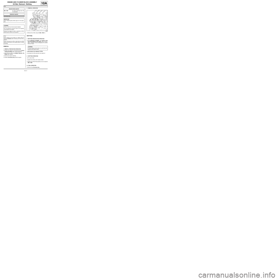
aRemove the oil filter using the (Mot. 1329) (1) .
REFITTING
I - REFITTING PREPARATION OPERATION
aUsing SURFACE CLEANER (see Vehicle: Parts
and consumables for the repair) (04B, Consum-
ables - Products), clean and degrease the cylinder
block joint faces.
aparts always to be replaced: Oil filter.
aLubricate the oil filter seal with new engine oil.
II - REFITTING OPERATION
aFit a new oil filter.
aTighten the oil filter until it makes contact.
aTighten the oil filter three-quarters of a turn using the
(Mot. 1329).
III - FINAL OPERATION
aRemove the oil recovery tray. Special tooling required
Mot. 1329Oil filter removing tool (76
mm diameter)
Equipment required
oil recovery tray
IMPORTANT
Wear leaktight gloves (Nitrile type) for this opera-
tion.
WARNING
Always check the oil level using the dipstick.
Do not exceed the maximum level on the dipstick
(could destroy the engine).
Correct the engine oil level if necessary before
deliver ing the vehicle to the customer.
Note:
When topping up the engine oil, always leave at
least 10 minutes before checking the level with a
dipstick.
When removing the oil filter, check that the oil filter
seal is not still stuck to the cylinder block or oil filter
mounting.
132364
WARNING
The joint faces must be clean, dr y and free from
grease (avoid finger marks).
Page 38 of 652
10A-32
ENGINE AND CYLINDER BLOCK ASSEMBLY
Oil filter: Removal - Refitting
K4M
10A
aWipe any oil run-off with a cloth.
aTop up the engine oil with oil recommended by the
manufacturer (see Engine oil: Specifications)
(Technical Note 6013A, 04A, Lubricants).
aConnect the battery (see Battery: Removal - Refit-
ting) (80A, Battery).
aStart the engine and wait until the oil pressure warn-
ing light goes out on the instrument panel.
aCheck for leaks from the oil filter.
aRefit the engine undertray.
aWait at least 10 minutes.
aCheck the oil level using the dipstick.
aAdjust the engine oil level if necessary.WARNING
Always check the oil level using the dipstick.
Do not exceed the maximum level on the dipstick
(could destroy the engine).
Correct the engine oil level if necessary before
delivering the vehicle to the customer.
Page 39 of 652
10A-33
ENGINE AND CYLINDER BLOCK ASSEMBLY
Oil-coolant heat exchanger: Removal - Refitting
K9K
10A
REMOVAL
I - REMOVAL PREPARATION OPERATION
aPosition the vehicle on a two-post lift (see Vehicle:
Towing and lifting) (MR 411, 02A, Lifting equip-
ment).
aRemove:
-the engine cover,
-the front wheels (see Wheel: Removal - Refitting)
(MR 411, 35A, Wheels and tyres),
-the front wheel arch liners (see Front wheel arch
liner: Removal - Refitting) (MR 412, 55A, Exterior
protection),
-the front bumper (see Front bumper: Removal -
Refitting) (MR 412, 55A, Exterior protection).
aDrain the cooling system (see 19A, Cooling, Cool-
ing system: Draining - Refilling, page 19A-9) .
aRemove the expansion bottle bolt.
aRemove the expansion bottle.
aUnclip the cooling hose on the lower section of the
engine cooling fan.II - OPERATION FOR REMOVAL OF PART
CONCERNED
aDisconnect:
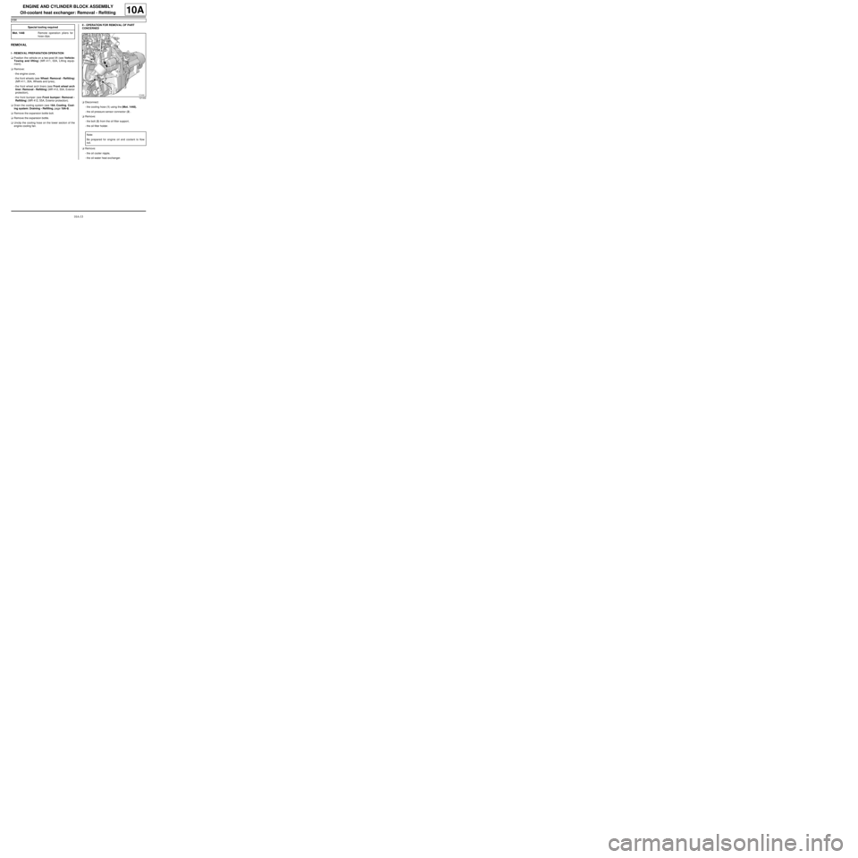
-the cooling hose (1) using the (Mot. 1448),
-the oil pressure sensor connector (2) .
aRemove:
-the bolt (3) from the oil filter support,
-the oil filter holder.
aRemove:
-the oil cooler nipple,
-the oil-water heat exchanger. Special tooling required
Mot. 1448Remote operation pliers for
hose clips .
121432
Note:
Be prepared for engine oil and coolant to flow
out.
Page 40 of 652
10A-34
ENGINE AND CYLINDER BLOCK ASSEMBLY
Oil-coolant heat exchanger: Removal - Refitting
K9K
10A
REFITTING
I - REFITTING PREPARATION OPERATION
aUsing the buffing pads, clean the pressure faces of
the oil-water heat exchanger and the cylinder block.
aFit new seals on the oil-water heat exchanger with
soapy water.
aCheck the condition of the oil-water heat exchanger
nipple seals.
II - REFITTING OPERATION FOR PART
CONCERNED
aCoat the nipple with high resistance thread lock.
aRefit:
-the coolant-oil heat exchanger,
-the oil-coolant heat exchanger nipple.
aFit a new seal on the oil filter holder.
aRefit:
-the oil filter holder,
-the oil filter mounting bolt.
aTighten the oil filter mounting bolt.
aConnect:
-the oil pressure sensor connector,
-the cooling hose using the (Mot. 1448).
III - FINAL OPERATION
aClip the cooling hose on to the lower section of the
engine cooling fan.
aPosition the expansion bottle.
aRefit the expansion bottle bolt.aFill the cooling system (see 19A, Cooling, Cooling
system: Draining - Refilling, page 19A-9) .
aRefit:
-the front bumper (see Front bumper: Removal -
Refitting) (MR 412, 55A, Exterior protection),
-the front wheel arch liners (see Front wheel arch
liner: Removal - Refitting) (MR 412, 55A, Exterior
protection),
-the front wheels (see Wheel: Removal - Refitting)
(MR 411, 35A, Wheels and tyres),
-the engine cover. WARNING
The joint faces must be clean, dr y and free from
grease (avoid finger marks).
WARNING
The gaskets must always be replaced with new
gaskets.
Note:
The oil-water heat exchanger nipple seals cannot
be separated; the entire assembly must be
replaced.
Page 41 of 652
10A-35
ENGINE AND CYLINDER BLOCK ASSEMBLY
Oil-coolant heat exchanger: Removal - Refitting
D4F, and 780 or 782
10A
REMOVAL
I - REMOVAL PREPARATION OPERATION
aPosition the vehicle on a two-post lift (see Vehicle:
Towing and lifting) (02A, Lifting equipment).
aRemove:
-the front right-hand wheel (see Wheel: Removal -
Refitting) (35A, Wheels and tyres),
-the front right-hand wheel arch liner (see Front
wheel arch liner: Removal - Refitting) (55A, Ex-
terior protection),
-the oil filter (see 10A, Engine and cylinder block
assembly, Oil filter: Removal - Refitting, page
10A-29) .II - OPERATION FOR REMOVAL OF PART
CONCERNED
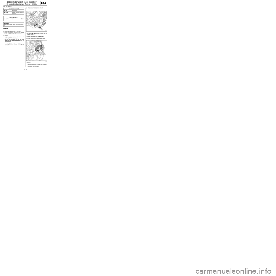
aFit the tool (Ms. 583) onto the oil-coolant heat ex-
changer hoses (1) .
aRelease the clips (2) using the (Mot. 1448).
aConnect the oil-coolant heat exchanger hoses.
aRemove:
-the nipple (3) from the oil-coolant heat exchanger,
-the oil-water heat exchanger. Special tooling required
Ms. 583Pipe clamps .
Mot. 1448Remote operation pliers for
hose clips .
Tightening torquesm
oil-coolant heat
exchanger nipple30 N.m
IMPORTANT
Wear leaktight gloves (Nitrile type) for this opera-
tion.121726
121402
Page 42 of 652
10A-36
ENGINE AND CYLINDER BLOCK ASSEMBLY
Oil-coolant heat exchanger: Removal - Refitting
D4F, and 780 or 782
10A
REFITTING
I - REFITTING PREPARATION OPERATION
aparts always to be replaced: coolant-engine oil
heat exchanger seal on the cylinder block.
aUse a GREY ABRASIVE PAD (see Vehicle: Parts
and consumables for the repair) (04B, Consum-
ables - Products) to clean the bearing faces of the
oil-coolant heat exchanger and the cylinder block.
II - REFITTING OPERATION FOR PART
CONCERNED
aCoat the nipple with HIGH STRENGTH THREAD-
LOCK (see Vehicle: Parts and consumables for
the repair) (04B, Consumables - Products).
aRefit:
-the oil-coolant heat exchanger,
-the oil-coolant heat exchanger nipple.
aTorque tighten the oil-coolant heat exchanger nip-
ple (30 N.m).
aConnect the oil-coolant heat exchanger hoses.
aRefit the clips using the (Mot. 1448).
aRemove the tools (Ms. 583).
III - FINAL OPERATION
aRefit:
-the oil filter (see 10A, Engine and cylinder block
assembly, Oil filter: Removal - Refitting, page
10A-29) ,
-the front right-hand wheel arch liner (see Front
wheel arch liner: Removal - Refitting) (55A, Ex-
terior protection),
-the front right-hand wheel (see Wheel: Removal -
Refitting) (35A, Wheels and tyres).
aFill and bleed the cooling system (see 19A, Cool-
ing, Cooling system: Draining - Refilling, page
19A-9) . WARNING
To ensure proper sealing, the gasket surfaces
must be clean, dry and not greasy (avoid any fin-
ger marks).