light RENAULT TWINGO RS 2009 2.G Engine Diesel Injection Service Manual
[x] Cancel search | Manufacturer: RENAULT, Model Year: 2009, Model line: TWINGO RS, Model: RENAULT TWINGO RS 2009 2.GPages: 269
Page 120 of 269
13B-120
AFTER REPAIRDeal with any faults displayed by the diagnostic tool.
Clear the computer fault memory.
Carry out a road test followed by another check with the diagnostic tool.
V6 MR-413-X44-13B000$120.mif
DIESEL INJECTION
Fault finding – Interpretation of faults13B
DCM 1.2 Injection
Program No.: 4D
Vdiag No.: 48, 4C, 50,
54, 58, 5C
DF648
PRESENT OR
STOREDCOMPUTER1.DEF: Enter EEPROM memory
2.DEF: Read EEPROM memory
NOTESSpecial notes:
When this fault appears:
the engine speed is locked at 1300 rpm, the engine is noisy, and the level 1 warning
light illuminates with the message Check injection displayed on the instrument panel,
Contact Techline.
DCM1.2_V48_DF648/DCM1.2_V4C_DF648/DCM1.2_V50_DF648/DCM1.2_V54_DF648/DCM1.2_V58_DF648/DCM1.2_V5C_DF648
Page 122 of 269
13B-122
AFTER REPAIRDeal with any faults displayed by the diagnostic tool.
Clear the computer fault memory.
Carry out a road test followed by another check with the diagnostic tool.
V6 MR-413-X44-13B000$120.mif
DIESEL INJECTION
Fault finding – Interpretation of faults13B
DCM 1.2 Injection
Program No.: 4D
Vdiag No.: 48, 4C, 50,
54, 58, 5C
DF886
PRESENT OR
STOREDPRESENCE OF WATER IN THE DIESEL FUEL
NOTESPriorities when dealing with a number of faults:
–DF057 Water in diesel fuel detector circuit,
Special notes:
If water is detected downstream of the diesel filter, the high pressure pump and
the injectors may be damaged.
The level 1 warning light is illuminated.
Use bornier Elé. 1681 for all operations on the engine management computer
connector.
See the Technical Note Wiring Diagrams for the vehicle.
If there is water present, bleed the diesel filter.
If there is a great amount of water, run the first part of Test 13: Diesel fuel conformity check (Is the fuel cloudy
or does it separate into 2 parts?)
Check the connections of the water in diesel fuel sensor, component code 414.
Check the connections of the engine management computer grey connector, component code 120.
If the connector(s) are faulty and there is a repair procedure (see Technical Note 6015A, Repairing electrical
wiring, Wiring: Precautions for repair), repair the connector(s), otherwise replace the wiring.
With the ignition on, check for +12 V on connections 3FB1 or 3FB2 (for New Twingo) or AP15 (for Kangoo 2) of
component 414.
Check for earth on connections M or 3WU (only for New Twingo) of component 120.
If the connection or connections are faulty and there is a repair procedure (see Technical Note 6015A, Electrical
wiring repair, Wiring: Precautions for repair), repair the wiring, otherwise replace the wiring.
DCM1.2_V48_DF886/DCM1.2_V4C_DF886/DCM1.2_V50_DF886/DCM1.2_V54_DF886/DCM1.2_V58_DF886/DCM1.2_V5C_DF886
Page 165 of 269
13B-165
AFTER REPAIRDeal with any faults. Clear the faults from the computer memory.
Switch off the ignition and carry out a road test followed by a test with the diagnostic
tool.
V6 MR-413-X44-13B000$150.mif
DIESEL INJECTION
Fault finding – Interpretation of statuses13B
DCM 1.2 Injection
Program No.: 4D
Vdiag No.: 48, 4C, 50,
54, 58, 5C
ET704
ET705BRAKE SWITCH NO. 1BRAKE SWITCH NO. 2
STATUS DEFINITIONACTIVE: This status indicates that the brake pedal is depressed.
INACTIVE: This status indicates that the brake pedal is released.
Note:
Statuses ET704 and ET705 should change status at the same time. In the event of inconsistency, refer to the
interpretation of fault DF050 Brake switch circuit.
Conformity check: Engine stopped, ignition on or engine running.
ACTIVE
OR
INACTIVEIf the brake lights are working, check the continuity and the absence of interference
resistance between the following connections:
–5A between components 160 and 120,
–BPT between components 160 and 645 (for Mégane II, Scénic II, Modus and Clio III),
–BPT2 between components 160 and 645 (for Kangoo 2),
–AP10 between components 160 and 1016 (for New Twingo),
–65A between components 160 and 645 (vehicle without ESP),
–65G between components 160 and 645 (vehicle with ESP).
If there is a repair method (see Technical Note 6015A, Repairing electrical wiring,
Wiring: Precautions for repair), repair the wiring, otherwise replace it.
If the brake lights are not operational, check:
–the condition and fitting of the brake switch,
–the condition and conformity of the brake lights fuse,
the conformity of the values in the following table:
DCM1.2_V48_ET704/DCM1.2_V4C_ET704/DCM1.2_V50_ET704/DCM1.2_V54_ET704/DCM1.2_V58_ET704/DCM1.2_V5C_ET704/
DCM1.2_V48_ET705/DCM1.2_V4C_ET705/DCM1.2_V50_ET705/DCM1.2_V54_ET705/DCM1.2_V58_ET705/DCM1.2_V5C_ET705
Page 166 of 269
13B-166
AFTER REPAIRDeal with any faults. Clear the faults from the computer memory.
Switch off the ignition and carry out a road test followed by a test with the diagnostic
tool.
V6 MR-413-X44-13B000$150.mif
DIESEL INJECTION
Fault finding – Interpretation of statuses13B
DCM 1.2 Injection
Program No.: 4D
Vdiag No.: 48, 4C, 50,
54, 58, 5C
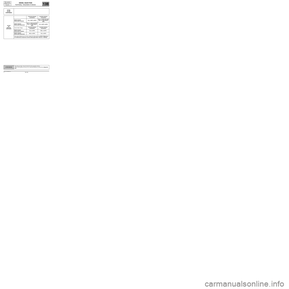
ET704
ET705
CONTINUED
ACTIVE
OR
INACTIVE
CONTINUEDContinuity between
connectionsInsulation between
connections
Switch pressed
(Brake pedal released)5A and BPT or BPT2SP17 and 65G (with ESP)
SP17 and 65A (without
ESP)
Switch released
(Brake pedal depressed)SP17 and 65G (with ESP)
SP17 and 65A (without
ESP)5A and BPT or BPT2
Only for New TwingoContinuity between
connectionsInsulation between
connections
Switch pressed
(Brake pedal released)5A and AP10 65A and AP10
Switch released
(Brake pedal depressed)65A and AP10 5A and AP10
If the values obtained are not correct, replace the brake switch (see MR 417 Mechanics,
37A, Mechanical component controls, Brake light Switch: Removal - Refitting).
Page 185 of 269
13B-185
AFTER REPAIRDeal with any faults displayed by the diagnostic tool. Clear the computer fault
memory.
Carry out a road test followed by another check with the diagnostic tool.
V6 MR-413-X44-13B000$170.mif
DIESEL INJECTION
Fault finding – Interpretation of parameters13B
DCM 1.2 Injection
Program No.: 4D
Vdiag No.: 48, 4C, 50,
54, 58, 5C
PR074BATTERY VOLTAGE
PARAMETER
DEFINITIONThis parameter indicates the battery voltage in Volts.
NOTESThere must be no present or stored faults.
Without electrical consumers (radio, air conditioning, fan assemblies, headlights,
etc.).
Conformity check: Engine stopped and ignition on, or engine running and engine coolant
temperature > 80
°C
12 V < PR074 < 14.4 V.
Ignition on then
at idle speedIf the voltage is at minimum:
Check the battery and the charge circuit (see 87B, Passenger compartment connection unit
for the New Twingo or see 87G, Engine compartment connection unit for Clio III, Modus,
Mégane II, Scénic II and Kangoo 2).
If the voltage is at maximum:
Check that the charging voltage is correct with and without electrical consumers switched on.
DCM1.2_V48_PR074/DCM1.2_V4C_PR074/DCM1.2_V50_PR074/DCM1.2_V54_PR074/DCM1.2_V58_PR074/DCM1.2_V5C_PR074