engine overheat RENAULT TWINGO RS 2009 2.G Engine Diesel Injection Workshop Manual
[x] Cancel search | Manufacturer: RENAULT, Model Year: 2009, Model line: TWINGO RS, Model: RENAULT TWINGO RS 2009 2.GPages: 269
Page 17 of 269
13B-17V6 MR-413-X44-13B000$040.mif
DIESEL INJECTION
Fault finding – Function13B
DCM 1.2 Injection
Program No.: 4D
Vdiag No.: 48, 4C, 50,
54, 58, 5C
Function: Hosted functions
Air conditioning management assistance
On models with air conditioning, the DCM1.2 system allows the air conditioning to be deactivated under certain
operating conditions:
–when requested by the driver,
–when starting the engine,
–if the engine overheats (in order to reduce the power the engine has to supply),
–when the engine speed is kept at a very high level (to protect the compressor),
–during transition phases (e.g. high acceleration demand for overtaking, anti-stalling and moving off). These
conditions are only taken into account if they do not occur repeatedly, so as to prevent system instabilities
(erratic deactivation),
–when certain faults appear.
Cold loop air conditioning management
The air conditioning is the cold loop type and its management shared between several computers. The injection
computer is responsible for:
–managing demand for cold air according to the passenger compartment commands and the pressure value,
–determining the power absorbed by the compressor from the pressure,
–determining the fan unit commands according to vehicle speed and pressure.
The driver requests the instrument panel to switch on the air conditioning. The signal is sent to the injection computer
via the multiplex line network. The cold air request is authorised or denied depending on the pressure measured. If
this pressure is outside the operating limits, the cold loop program is not activated.
Thermal regulation of the passenger compartment heating circuit
In a direct injection engine, fuel is injected directly into the combustion chamber. This leads to heat being lost
through the upper part of the engine and consequently, the cylinder head cooling system is smaller in size.
The effect of this is that the temperature of the coolant which flows through this circuit rises more slowly. This coolant
is also used by the passenger compartment heating system. In very cold conditions, it is therefore difficult to achieve
a comfortable passenger compartment temperature quickly.
To reduce the time taken to produce heat, air heating elements, called passenger compartment heating resistors,
are fitted in the passenger compartment heating circuit. The UCH decides whether or not to switch on the passenger
compartment heating resistors, and the UPC or the injection physically controls the heating elements. The injection
computer determines whether to reduce the power supplied to the passenger compartment heating resistors
according to the alternator load and also whether to inhibit the operation of the passenger compartment heating
resistors according to the engine speed, the load, and the vehicle speed.Note:
Fan unit actuation requests can be sent by the injection computer, but these are sent via the multiplex line. These
requests depend on the air conditioning, but also on the engine coolant temperature and vehicle speed.
Page 19 of 269
13B-19V6 MR-413-X44-13B000$040.mif
DIESEL INJECTION
Fault finding – Function13B
DCM 1.2 Injection
Program No.: 4D
Vdiag No.: 48, 4C, 50,
54, 58, 5C
Instrument panel display
The computer manages the data display on the instrument panel relating to engine operation. This covers five
functions: the OBD warning light for European On Board Diagnostics (EOBD), pre-postheating, coolant temperature,
and Level 1 (non critical fault) and Level 2 (emergency stop) engine faults. These five functions are represented by
five warning lights or messages displayed by the trip computer.
Pre-postheating warning light
This warning light indicates that preheating is active.
Engine coolant temperature warning light
This warning light is used as an engine overheating indicator.
–In the event of overheating, it is up to the driver whether to stop the vehicle or continue driving.
OBD warning light
The OBD fault warning light is used to warn the driver of the presence of injection faults producing excessive
pollution or that the EOBD system is deactivated.
The injection computer requests illumination of the OBD warning light for a present fault only after three consecutive
driving cycles.
The visual check of the warning light when the power is switched on (automatic test procedure managed by
the instrument panel) is carried out by the injection computer. It lasts 3 seconds or until the engine starts for
the New Twingo and Kangoo 2.
If a confirmed OBD fault causes the OBD warning light to come on, there should be no flashing after the warning
light illumination test. The instrument panel will also display the message: Check emission control.
The gearbox computer, if fitted, may also request the illumination of this warning light.
Level 1 warning
If there is a minor fault, the computer may request a level 1 warning to be displayed. Usually, the instrument panel
switches on the SERVICE warning light and sends out a "Check the injection" message. Refer to the operation of the
instrument panel (see 83A, instrument panel). Note:
This warning light comes on only if the vehicle is EOBD approved.
Note:
The SERVICE warning light will come on if the instrument panel is configured as cruise control - speed
limiter present, but the function has not yet been detected by the injection computer.
Page 47 of 269
13B-47
AFTER REPAIRDeal with any faults displayed by the diagnostic tool.
Clear the computer fault memory.
Carry out a road test followed by another check with the diagnostic tool.
V6 MR-413-X44-13B000$090.mif
DIESEL INJECTION
Fault finding – Interpretation of faults13B
DCM 1.2 Injection
Program No.: 4D
Vdiag No.: 48, 4C, 50,
54, 58, 5C
DF016
PRESENT
OR STOREDEGR VALVE CONTROL CIRCUITCC.0: Short circuit to earth
CC.1: Short circuit to +12 volts
1.DEF: Detection of overheating
CO.0: Open circuit or short circuit to earth
CO.1: Open circuit or short circuit to +12 V
CO: Open circuit
NOTESConditions for applying fault finding procedures to stored faults:
The fault is present with the engine idling.
Special notes:
If fault DF016 is present: unstable engine speed and even stalling.
Starting difficult or even impossible when cold.
See the Technical Note Wiring Diagrams for the vehicle.
K9K 724, 740, 766, 768, 800, 802, and 812 ENGINES (Euro 4):
Check the connection and condition of the exhaust gas recirculation valve connector, component code 1460.
Check the connection and condition of connector B (brown 48-track) of the injection computer, component
code 120.
If the connector(s) is faulty and if there is a repair procedure (see Technical Note 6015A, Repairing electrical
wiring, Wiring: Precautions for repair), repair the connector, otherwise replace the wiring.
Check the insulation and continuity of the following connections:
–3VP between components 1460 and 120,
–3VQ between components 1460 and 120.
If the connection or connections are faulty and there is a repair procedure (see Technical Note 6015A, Electrical
wiring repair, Wiring: Precautions for repair), repair the wiring, otherwise replace the wiring.
Check for the supply 13 V < X < 14 V (with the engine running), 11.5 V < X < 12.5 V (with the ignition on
and the engine stopped) on connection 3VP of component 1460.
Check for earth on connection 3VQ of component 1460.
DCM1.2_V48_DF016/DCM1.2_V4C_DF016/DCM1.2_V50_DF016/DCM1.2_V54_DF016/DCM1.2_V58_DF016/DCM1.2_V5C_DF016
Page 52 of 269
13B-52V6 MR-413-X44-13B000$090.mif
DIESEL INJECTION
Fault finding – Interpretation of faults13B
DCM 1.2 Injection
Program No.: 4D
Vdiag No.: 50, 58
DF019
PRESENT
OR STOREDHIGH SPEED FAN ASSEMBLY CONTROL CIRCUITCC.1: Short circuit to +12 volts
CO.0: Open circuit or short circuit to earth
NOTESConditions for applying the fault finding procedure to stored faults:
The fault reappears after:
–the ignition is switched on,
–clearing the fault from the memory,
–relay actuated using command AC153 High speed fan assembly.
Special notes:
–the level 1 warning light is illuminated,
–risk of overheating and air conditioning cut-off.
–Use bornier Elé. 1681 for all operations on the connector of the engine management
computer.
–See the Technical Note Wiring Diagrams for the vehicle.
Check the connections of the high-speed fan assembly relay mounting, component code 234.
Check the connections of the engine management computer, component code 120.
If the connector(s) are faulty and if there is a repair procedure (see Technical Note 6015A, Repairing electrical
wiring, Wiring: Precautions for repair) repair the connector(s), otherwise replace the wiring.
Run command AC153 High speed fan assembly.
If the command does not work, with the ignition on, check for + 12 V on connection 3FB of component 234
and the earth of connection 3JP of component 234.
Remove the high speed relay and check the continuity of the following connections:
–3FB between components 238 and 234,
–3JP between components 120 and 234.
If the fault is still present, check the relay and replace it if necessary.
If the fault is still present, contact the Techline.
AFTER REPAIRDeal with any faults displayed by the diagnostic tool.
Clear the computer fault memory.
Carry out a road test followed by another check with the diagnostic tool.
DCM1.2_V50_DF019/DCM1.2_V58_DF019
Page 135 of 269
13B-135
AFTER REPAIRDeal with any faults. Clear the faults from the computer memory.
Switch off the ignition and carry out a road test followed by a test with the diagnostic
tool.
V6 MR-413-X44-13B000$150.mif
DIESEL INJECTION
Fault finding – Interpretation of statuses13B
DCM 1.2 Injection
Program No.: 4D
Vdiag No.: 48, 4C, 50,
54, 58, 5C
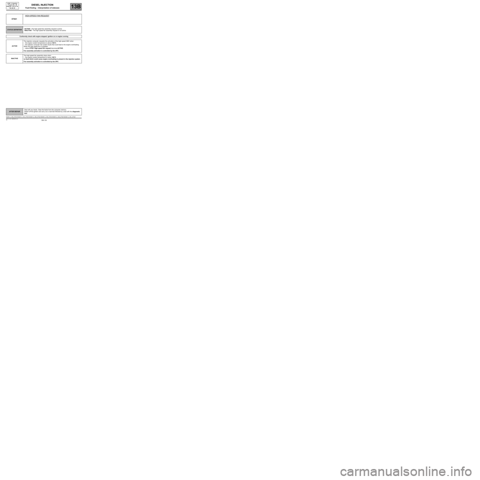
ET021HIGH-SPEED FAN REQUEST
STATUS DEFINITION"ACTIVE": The high speed fan assembly request is active.
"INACTIVE": The high speed fan assembly request is not active.
Conformity check with engine stopped, ignition on or engine running
ACTIVEThe injection computer requests the activation of the high speed GMV when:
–the engine coolant temperature is above 104˚C,
–the injection computer has system faults that could lead to the engine overheating.
When the high speed fan is supplied:
–status ET021 High speed fan request becomes ACTIVE.
Fan assembly activation is controlled by the UPC.
INACTIVEThe high-speed fan assembly stops when:
–the engine coolant temperature is below 102˚C,
no fault which could cause engine overheating is present in the injection system.
Fan assembly activation is controlled by the UPC.
DCM1.2_V48_ET021/DCM1.2_V4C_ET021/DCM1.2_V50_ET021/DCM1.2_V54_ET021/DCM1.2_V58_ET021/DCM1.2_V5C_ET021
Page 136 of 269
13B-136
AFTER REPAIRDeal with any faults. Clear the faults from the computer memory.
Switch off the ignition and carry out a road test followed by a test with the diagnostic
tool.
V6 MR-413-X44-13B000$150.mif
DIESEL INJECTION
Fault finding – Interpretation of statuses13B
DCM 1.2 Injection
Program No.: 4D
Vdiag No.: 48, 4C, 50,
54, 58, 5C
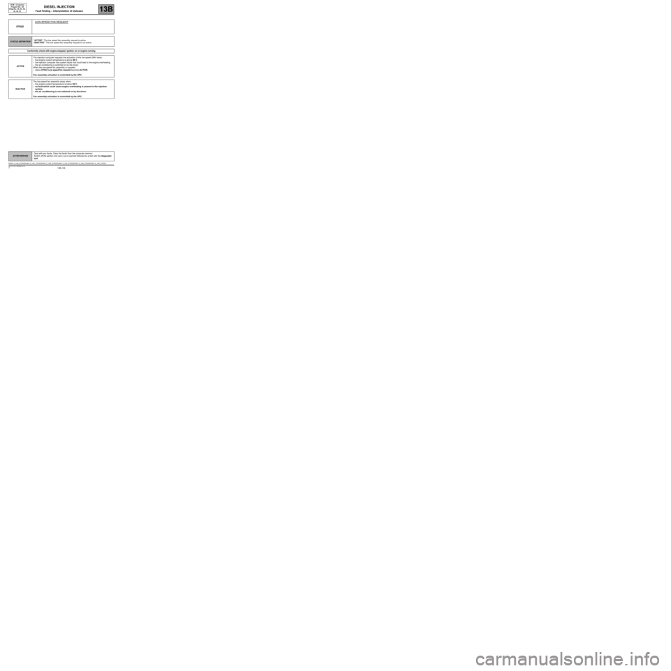
ET022LOW-SPEED FAN REQUEST
STATUS DEFINITION"ACTIVE": The low speed fan assembly request is active.
"INACTIVE": The low speed fan assembly request is not active.
Conformity check with engine stopped, ignition on or engine running
ACTIVEThe injection computer requests the activation of the low speed GMV when:
–the engine coolant temperature is above 96˚C,
–the injection computer has system faults that could lead to the engine overheating,
–the air conditioning is switched on by the driver.
When the low-speed fan assembly is supplied:
–status ET022 Low speed fan request becomes ACTIVE.
Fan assembly activation is controlled by the UPC.
INACTIVEThe low-speed fan assembly stops when:
–the engine coolant temperature is below 94˚C,
–no fault which could cause engine overheating is present in the injection
system.
–the air conditioning is not switched on by the driver.
Fan assembly activation is controlled by the UPC.
DCM1.2_V48_ET022/DCM1.2_V4C_ET022/DCM1.2_V50_ET022/DCM1.2_V54_ET022/DCM1.2_V58_ET022/DCM1.2_V5C_ET022