sensor RENAULT TWINGO RS 2009 2.G Heating And Air Conditioning - Climate Control User Guide
[x] Cancel search | Manufacturer: RENAULT, Model Year: 2009, Model line: TWINGO RS, Model: RENAULT TWINGO RS 2009 2.GPages: 99
Page 26 of 99
62B-26
MR-413-X44-62B000$414_eng.mif
V1
CLIMATE CONTROL
Fault finding - Interpretation of faults
Vdiag No.: 44
62B
DF007
PRESENT
OR
STOREDINTERIOR TEMPERATURE SENSOR CIRCUIT
CC.0 : Short circuit to earth
CO.1 : Short circuit or open circuit to + 12 V
NOTESConditions for running fault finding on a present or stored fault:
Apply this fault finding procedure if the fault reappears as present or stored after the
ignition is switched on and air conditioning activation is requested with the engine
running.
Special notes:
The interior temperature sensor is located at the top of the roof in the unit under the
rear view mirror.
Use the Wiring Diagram Technical Note for the New Twingo.
Check the connection and condition (possible wiring damage) of the connector of component 1872.
If the connector is faulty (see Technical Note 6015A, Repairing electrical wiring, Wiring: Precautions for the
repair), repair the connector, otherwise replace the wiring.
With connector A of component 419 and connector of union R301 disconnected, check the insulation and
continuity of the following connections between components R301 (dashboard/interior lights intermediate union)
and 419.
●connection 38JN
●connection 38GZ
If the connection or connections are faulty (see Technical Note 6015A, Repairing electrical wiring, Wiring:
Precautions for repair), repair the wiring, otherwise replace it.
With the connector of component 1872 disconnected, check the insulation and continuity of the following
connections between components R301 (dashboard/interior lights intermediate union) and 1872.
●connection 38JN
●connection 38GZ
If the connection or connections are faulty (see Technical Note 6015A, Repairing electrical wiring, Wiring:
Precautions for repair), repair the wiring, otherwise replace it.
Check the insulation of connections 38JN and 38GZ of component 1872.
If the connection or connections are faulty and there is a repair procedure (see Technical Note 6015A, Electrical
wiring repair, Wiring: Precautions for repair), repair the wiring, otherwise replace it.
Check the resistance of component 1872 between connections 38JN and 38GZ.
Replace the sensor if the resistance is not 10 kΩΩ Ω Ω
± 500 ΩΩ Ω Ω
at 25 ˚C. For more details, consult the electrical
specifications of the sensor according to the temperature (see Help).
If the fault is still present, contact the Techline.
AFTER REPAIRClear the stored faults.
Follow the instructions to confirm repair.
Deal with any other faults.
CLIM_V44_DF007
Page 32 of 99
62B-32
MR-413-X44-62B000$460_eng.mif
V1
62B
CLIMATE CONTROL
Fault finding - Conformity check
SUB-FUNCTION: PASSENGER COMPARTMENT VENTILATION
NOTESOnly carry out this conformity check after a complete check with the diagnostic tool
(fault reading and configuration checks).
Application conditions: engine stopped with ignition on (12 V APC), AIR
CONDITIONING OFF (air conditioning compressor not activated).
Note:
–Read the parameters when the vehicle is cold (in the morning) to check the
conformity of the temperature parameters (without thermometer). The two
temperatures should be practically the same (as should the coolant temperature
given by the injection system).
–The invalid values given in this check correspond to the value sent by the diagnostic
tool (substitute value) when the sensor in question is faulty. A sensor fault can be
detected when these invalid values are displayed (this is an important point for
sensors on which fault finding cannot be performed, e.g. exterior temperature
sensor).
Delayed illumination of the exterior temperature sensor LCD indicates that an invalid
value has been received concerning the exterior temperature sensor.
FunctionParameter or Status
checked or ActionDisplay and Notes Fault finding
Passenger
compartment
blowerET141:Passenger
compartment
blowerRUNNING
or
STOPPED
After a user requestIn the event of a fault, refer to the
interpretation of this status.
PR019:Passenger
compartment
fan PWM settingSpeed 0 = 0 %
Speed 8 = 100 %
Note:
The PWM signal is a
modulated control
voltage used to control
the air conditioning
blower power module.If there is a fault or for more
information (to find the
intermediate speed
percentages), refer to the
interpretation of this
parameter.
Note:
If the parameter varies correctly,
but the passenger compartment
blower unit does not operate:
consult ALP 5 "Air flow fault"
Air flapsPR012:Mixing flap
positionFrom 0 % (“Maximum
cold” position: 15 ˚C)
to 100 % (“Maximum
hot” position: 27 ˚C).In the event of a fault, see the
interpretation of this
parameter.
ET062:Recirculation
flap positionOPEN if the flap is in the
external air position.
CLOSED if the flap is in
the recirculation
position.In the event of a fault, refer to the
interpretation of this status.
PR011:Distribution flap
positionFrom 0 % (Air vent
position)
to 100 % (De-icing
position)In the event of a fault, see the
interpretation of this
parameter.
CLIM_V44_CCONF
Vdiag No.: 44
MR-413-X44-62B000$460_eng.mif
Page 37 of 99
62B-37
MR-413-X44-62B000$460_eng.mif
V1
Vdiag No.: 44CLIMATE CONTROL
Fault finding - Conformity check62B
SUB-FUNCTION: PASSENGER COMPARTMENT VENTILATION
NOTESOnly carry out this conformity check after a full check using the diagnostic tool
(fault reading and configuration checks).
Application conditions: engine running, AIR CONDITIONING ON (air conditioning
compressor activated).
Note:
–Read the parameters when the vehicle is cold (in the morning) to check the
conformity of the temperature parameters (without thermometer). The two
temperatures should be practically the same (as should the coolant temperature
given by the injection system).
–The invalid values given in this check correspond to the value sent by the diagnostic
tool (substitute value) when the sensor in question is faulty. A sensor fault can be
detected when these invalid values are displayed (this is an important point for
sensors on which fault finding cannot be performed, e.g. exterior temperature
sensor).
FunctionParameter or Status
checked or ActionDisplay and Notes Fault finding
Passenger
compartment
blowerPR019: Passenger
compartment
fan PWM settingSpeed 0 = 0 %
Speed 8 = 100 %
Note:
The PWM signal is a
modulated control
voltage used to control
the air conditioning
blower power module.If there is a fault or for more
information (to find the
intermediate speed
percentages), refer to the
interpretation of this
parameter.
Note:
If the parameter varies correctly,
but the passenger compartment
blower unit is not working: refer to
fault finding chart no. 5.
ET141: Passenger
compartment
blowerRUNNING
or
STOPPED
After a user request.In the event of a fault, refer to the
interpretation of this status.
Air flapsPR012: Mixing flap
positionFrom 0 % (“Maximum
cold” position: 15 ˚C)
to 100 % (“Maximum
hot” position: 27 ˚C).In the event of a fault, see the
interpretation of this
parameter.
ET062: Recirculation
flap positionOPEN if the flap is in the
external air position.
CLOSED if the flap is in
the recirculation
position.In the event of a fault, refer to the
interpretation of this status.
PR011: Distribution flap
positionFrom 0 % (Air vent
position)
to 100 % (De-icing
position).In the event of a fault, refer to the
interpretation of this status.
Page 52 of 99
62B-52
MR-413-X44-62B000$644_eng.mif
V1
62B
CLIMATE CONTROL
Fault finding - Interpretation of parameters
PR001
INTERIOR TEMPERATURE
NOTESNone
The climate control computer receives the interior temperature signal through a wire connection.
Read the temperature signal when the vehicle is cold (in the morning) to check the conformity of this parameter
(without a thermometer). The interior temperature, the exterior temperature and the engine coolant temperature
should be practically the same.
Another way of checking whether this sensor is correct is to check the resistance value of the sensor according to
temperature: refer to the electrical specifications of the sensor in the Help section (at the end of the document).
If the temperature displayed by this parameter is implausible, apply the fault finding procedure for fault: DF007
Interior temperature sensor circuit.
AFTER REPAIRRepeat the conformity check from the start.
CLIM_V44_PR001
Vdiag No.: 44
MR-413-X44-62B000$644_eng.mif
Page 68 of 99
62B-68
MR-413-X44-62B000$828_eng.mif
V1
62B
CLIMATE CONTROL
Diagnostic - Fault finding chart
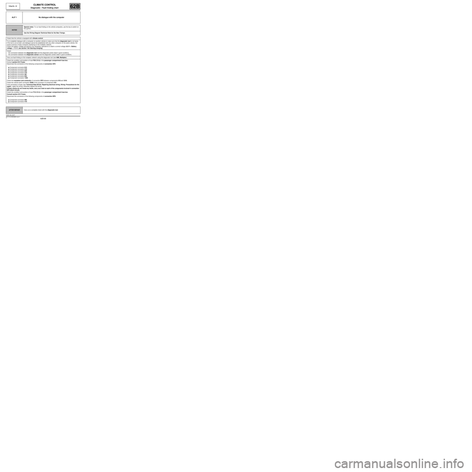
ALP 1 No dialogue with the computer
NOTESSpecial notes: To run fault finding on the vehicle computers, use the key to switch on
the ignition.
Use the W iring Diagram Technical Note for the New Twingo.
Check that the vehicle is equipped with climate control.
Try to establish dialogue with a computer on another vehicle to make sure that the diagnostic tool is not faulty.
If the tool is not at fault, and dialogue cannot be established with any other computer on the same vehicle, the
cause could be a faulty computer interfering on the multiplex network.
Check the battery voltage and perform the necessary operations to obtain a correct voltage (9.5 V < Battery
voltage < 17.5 V, see section 16A Starting-charging).
Check:
–the connection between the diagnostic tool and the diagnostic probe (lead in good condition),
–the connection between the diagnostic sensor and the diagnostic socket (lead in good condition).
Carry out fault finding on the multiplex network using the diagnostic tool (see 88B, Multiplex).
Check the condition and position of fuse F29 (15 A) in the passenger compartment fuse box.
Consult section 81C Fuses.
Disconnect the connectors of the following components of connection SP2:
●Component connector 615
●Component connector 419
●Component connector 645
●Component connector 319
●Component connector 261
●Component connector 653
●Component connector 1428
Check the insulation and continuity of connection SP2 between components 419 and 1016.
Check the vehicle earth connection NAM of the connector of component 419.
If the connection is faulty (see Technical Note 6015A, Repairing electrical wiring, Wiring: Precautions for the
repair), repair the wiring, otherwise replace the wiring.
If these checks do not reveal any faults, carry out a test on each of the components involved in connection
SP2 (short circuit).
Check the condition and position of fuse F18 (10 A) in the passenger compartment fuse box.
Consult section 81C Fuses.
Disconnect the connectors of the following components of connection BP6:
●Component connector 995
●Component connector 419
AFTER REPAIRCarry out a complete check with the diagnostic tool.
CLIM_V44_ALP1
Vdiag No.: 44
MR-413-X44-62B000$828_eng.mif
Page 73 of 99
62B-73
MR-413-X44-62B000$828_eng.mif
V1
Vdiag No.: 44CLIMATE CONTROL
Diagnostic - Fault finding chart62B
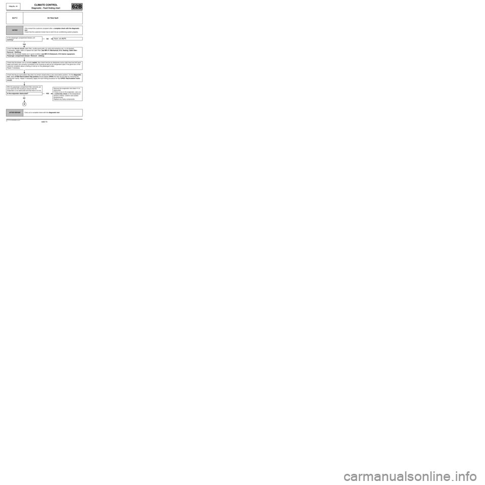
ALP 3 Air flow fault
NOTESOnly consult this customer complaint after a complete check with the diagnostic
tool.
Check that the customer knows how to work the air conditioning system properly.
Is the passenger compartment blower unit
working?
YES
Check that the air circuit (cabin filter, scuttle panel grille, air vents and extractors etc.) is not blocked.
If necessary, repair, clean or replace the cabin filter (see MR 411 Mechanical, 61A, Heating, Cabin filter:
Removal - Refitting).
Check that the blower blades are in good condition (see MR 412 Bodywork, 57A Interior equipment,
Passenger compartment blower: Removal - refitting).
Check that the blower unit is correctly sealed. Also check that the air distribution ducts (right-hand and left-hand,
upper and lower) are correctly connected to the housing as well as the refrigeration pipe in the glove box (if the
customer complains about a feeling of cold air on the passenger's side).
Repair if necessary.
Check that the air recirculation flap does not remain closed when in the recirculation position. On the diagnostic
tool, status ET062 Recirculation flap position should display OPEN (the flap can be seen by removing the
windscreen frame). Repair if necessary (apply the fault finding procedure for fault DF021 Recirculation motor
circuit).
With the passenger compartment filter removed, put
your hand into the housing to ensure that the
evaporator is not obstructed and that there is no ice.
Is the evaporator obstructed?
NO
NORepair, see ALP 5.
YESRemove the evaporator and clean if it is
obstructed.
If there is ice on the evaporator, carry out
a conformity check on the temperature
sensors (interior, exterior and coolant
temperatures).
Replace any faulty components.
AFTER REPAIRCarry out a complete check with the diagnostic tool.
Page 76 of 99
62B-76
MR-413-X44-62B000$828_eng.mif
V1
Vdiag No.: 44CLIMATE CONTROL
Diagnostic - Fault finding chart62B
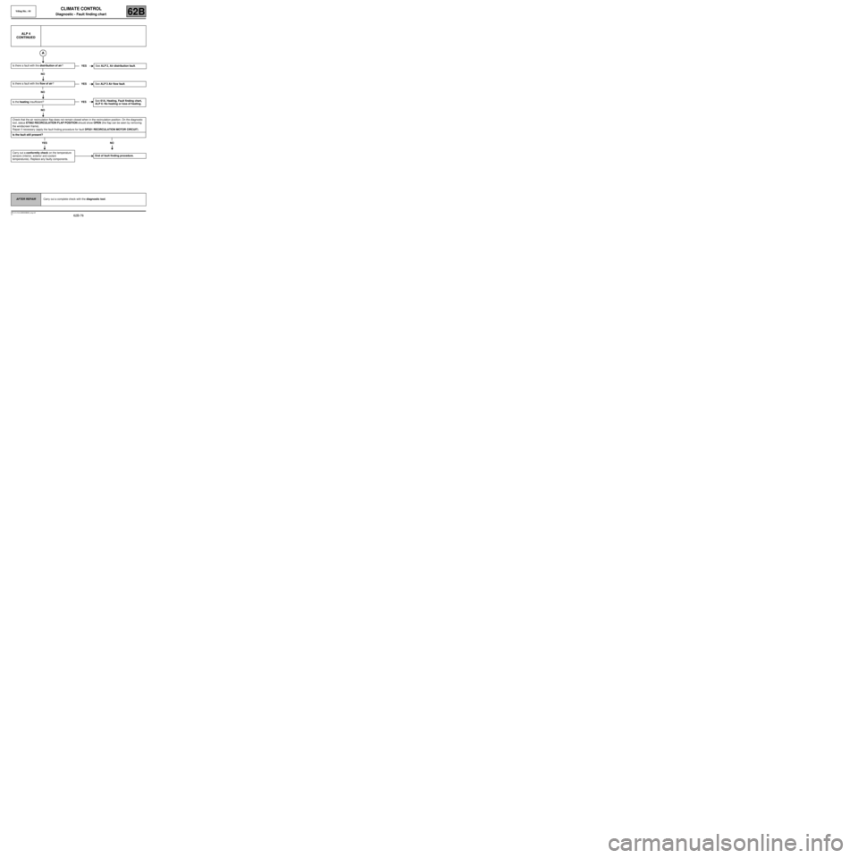
ALP 4
CONTINUED
Is there a fault with the distribution of air?
NO
Is there a fault with the flow of air?
NO
Is the heating insufficient?
NO
Check that the air recirculation flap does not remain closed when in the recirculation position. On the diagnostic
tool, status ET062 RECIRCULATION FLAP POSITION should show OPEN (the flap can be seen by removing
the windscreen frame).
Repair if necessary (apply the fault finding procedure for fault DF021 RECIRCULATION MOTOR CIRCUIT).
Is the fault still present?
YES NO
Carry out a conformity check on the temperature
sensors (interior, exterior and coolant
temperatures). Replace any faulty components.YESSee ALP 2, Air distribution fault.
YESSee ALP 3 Air flow fault.
YESSee 61A, Heating, Fault finding chart,
ALP 6: No heating or loss of heating.
End of fault finding procedure.
AFTER REPAIRCarry out a complete check with the diagnostic tool.
Page 80 of 99
62B-80
MR-413-X44-62B000$874_eng.mif
V1
Vdiag No.: 44CLIMATE CONTROL
Diagnostic - Fault finding chart62B
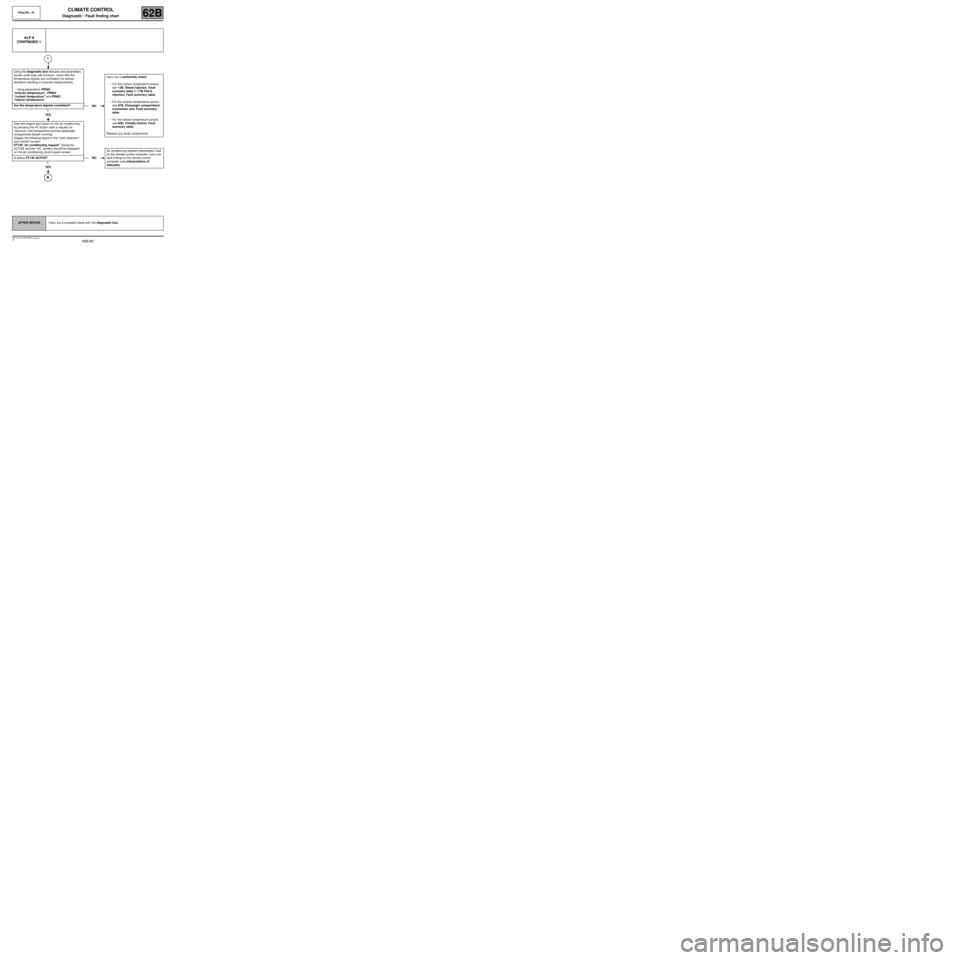
ALP 8
CONTINUED 1
1
Using the diagnostic tool statuses and parameters
screen (cold loop sub-function), check that the
temperature signals are consistent (no sensor
deviation resulting in incorrect measurement).
–Using parameters PR002
"exterior temperature", PR064
"coolant temperature" and PR001
"interior temperature".
Are the temperature signals consistent?
YES
Start the engine and switch on the air conditioning
by pressing the AC button (with a request for
maximum cold temperature and the passenger
compartment blower running).
Display the following status in the “User selection”
sub-function screen:
ET140 "air conditioning request" should be
ACTIVE and the “AC” symbol should be displayed
on the air conditioning control panel screen.
Is status ET140 ACTIVE?
YES
NOCarry out a conformity check:
–For the coolant temperature sensor,
see 13B, Diesel injection, Fault
summary table or 17B Petrol
injection, Fault summary table.
–For the exterior temperature sensor,
see 87B, Passenger compartment
connection unit, Fault summary
table.
–For the interior temperature sensor,
see 62B, Climate control, Fault
summary table.
Replace any faulty components.
NOAir conditioning request interpretation fault
on the climate control computer. Carry out
fault finding on the climate control
computer (see interpretation of
statuses).
AFTER REPAIRCarry out a complete check with the diagnostic tool.
Page 88 of 99
62B-88
MR-413-X44-62B000$874_eng.mif
V1
Vdiag No.: 44CLIMATE CONTROL
Diagnostic - Fault finding chart62B
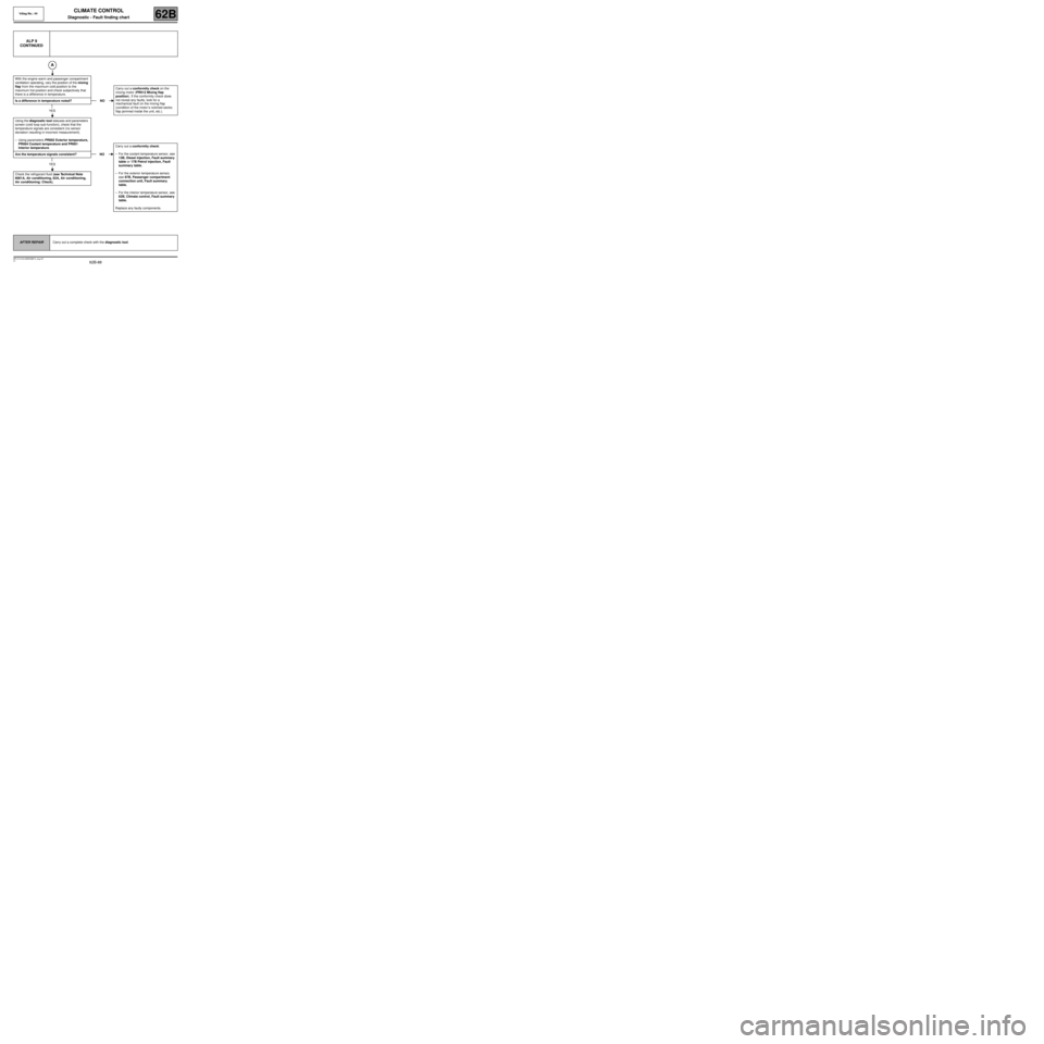
ALP 9
CONTINUED
With the engine warm and passenger compartment
ventilation operating, vary the position of the mixing
flap from the maximum cold position to the
maximum hot position and check subjectively that
there is a difference in temperature.
Is a difference in temperature noted?
YES
Using the diagnostic tool statuses and parameters
screen (cold loop sub-function), check that the
temperature signals are consistent (no sensor
deviation resulting in incorrect measurement).
–Using parameters PR002 Exterior temperature,
PR064 Coolant temperature and PR001
Interior temperature.
Are the temperature signals consistent?
YES
Check the refrigerant fluid (see Technical Note
6001A, Air conditioning, 62A, Air conditioning,
Air conditioning: Check).
NOCarry out a conformity check on the
mixing motor (PR012 Mixing flap
position). If the conformity check does
not reveal any faults, look for a
mechanical fault on the mixing flap
(condition of the motor ’s notched sector,
flap jammed inside the unit, etc.).
NOCarry out a conformity check:
–For the coolant temperature sensor, see
13B, Diesel injection, Fault summary
table or 17B Petrol injection, Fault
summary table.
–For the exterior temperature sensor,
see 87B, Passenger compartment
connection unit, Fault summary
table.
–For the interior temperature sensor, see
62B, Climate control, Fault summary
table.
Replace any faulty components.
AFTER REPAIRCarry out a complete check with the diagnostic tool.
Page 93 of 99
62B-93
MR-413-X44-62B000$920_eng.mif
V1
Vdiag No.: 44CLIMATE CONTROL
Diagnostic - Fault finding chart62B
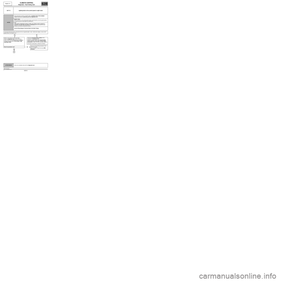
ALP 13 Lighting fault on the control panel in night mode
NOTESOnly consult this customer complaint after a complete check of the multiplex
network and the air conditioning with the diagnostic tool.
Special notes:
With the ignition on, the control panel screen is permanently on but the panel buttons
only light up when the side lights are switched on.
Note:
If the exterior temperature sensor is faulty, the climate control computer is
activated 5 seconds after the ignition is switched on (the UCH performs fault
finding on the exterior temperature sensor).
Use the Wiring Diagram Technical Note for the New Twingo.
Is the fault shared with other components (first row cigarette lighter, radio, multifunction display, cruise control/
speed limiter on off switch, etc.)
YES NO
Switch on the ignition and the side lights.
Using the diagnostic tool and the conformity
check, check that the lighting dimmer is operating
correctly using parameter PR122 NIGHT TIME
LIGHTING LEVEL.
Does the parameter vary?
YES
Check the connection and condition of the
connector of component 419.
If there is a repair method (see Technical Note
6015A, Electrical wiring repair, Wiring: Repair
precautions), repair the wiring, otherwise replace it.
If the fault is still present, contact the Techline.
NOCarry out a fault finding procedure of the
instrument panel.
Run a multiplex network test (see 88B,
Multiplex).
AFTER REPAIRCarry out a complete check with the diagnostic tool.
CLIM_V44_ALP13