check engine RENAULT TWINGO RS 2009 2.G Heating And Air Conditioning - Climate Control Owner's Manual
[x] Cancel search | Manufacturer: RENAULT, Model Year: 2009, Model line: TWINGO RS, Model: RENAULT TWINGO RS 2009 2.GPages: 99
Page 64 of 99
62B-64
MR-413-X44-62B000$736_eng.mif
V1
CLIMATE CONTROL
Fault finding - Interpretation of commands
Vdiag No.: 44
62B
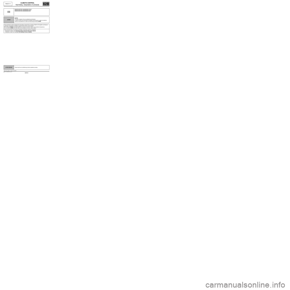
AC004
AC005
MIXER MOTOR: MAXIMUM COLD
MIXER MOTOR: MAXIMUM HOT
NOTESNOTES:
The flap is located in the air conditioning mechanism.
In order to confirm this command, the engine must be warm in order to be able to
check for the presence of a warm air flow during command AC005.
This command is used to activate the mixing flap to check that it is working. Switch on the ignition, and issue a
passenger compartment ventilation request (via the driver's control panel).
Run command AC004 and check that the air coming out of the air vents is cold (ambient temperature).
Run command AC005 and check that the air coming out of the air vents is warm.
If the command does not operate as indicated, consult the customer complaints:
–Production of cold air, see: ALP 8 No cold air and ALP 9 Too much cold air.
–Production of warm air, see: ALP 6 No heating or loss of heating.
AFTER REPAIRCheck that the air conditioning function operates correctly.
CLIM_V44_AC004 / CLIM_V44_AC005
Page 79 of 99
62B-79
MR-413-X44-62B000$874_eng.mif
V1
62B
CLIMATE CONTROL
Diagnostic - Fault finding chart
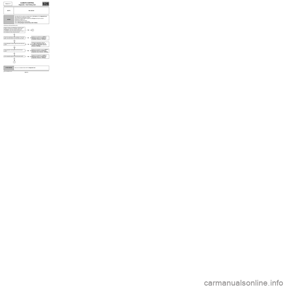
Preliminary cold loop efficiency test
ALP 8 No cold air
NOTESOnly deal with this customer complaint after a full check with the diagnostic tool
(fault reading and configuration checks).
Check that the engine speed is greater than 750 rpm and that the exterior
temperature is above 3 ˚C.
Check that the fuses are sound.
Use a multimeter and a 21 W test light.
Use the Wiring Diagram Technical Note, NEW TWINGO.
Engine running, air conditioning in maximum cold
position and maximum ventilation speed. After
10 minutes, is the high pressure pipe at the
compressor outlet hot, and the low pressure pipe at
the evaporator outlet cold and iced up?
NO
Check the cleanliness of the condenser. Touch the
pipes: are they warmer at the inlet than the outlet?
YES
Is the dehydrator reservoir pipe hot at the inlet and
outlet?
YES
Is the expansion valve pipe hot at the inlet and
outlet?
NO
Is the evaporator pipe hot at the inlet and outlet?
NO
1
YES2
NOReplace the condenser (see MR 411
Mechanical, 62A, Air conditioning,
Condenser: Removal - Refitting).
NOReplace the dehydrator reservoir
(see MR 411 Mechanical, 62A, Air
conditioning, Dehydrator reservoir:
Removal - Refitting).
YESReplace the expansion valve (see MR 411
Mechanical, 62A, Air conditioning,
Expansion valve: Removal - Refitting).
YESReplace the evaporator (see MR 411
Mechanical, 62A, Air conditioning,
Evaporator: Removal - Refitting).
AFTER REPAIRCarry out a complete check with the diagnostic tool.
Vdiag No.: 44
MR-413-X44-62B000$874_eng.mif
Page 80 of 99
62B-80
MR-413-X44-62B000$874_eng.mif
V1
Vdiag No.: 44CLIMATE CONTROL
Diagnostic - Fault finding chart62B
ALP 8
CONTINUED 1
1
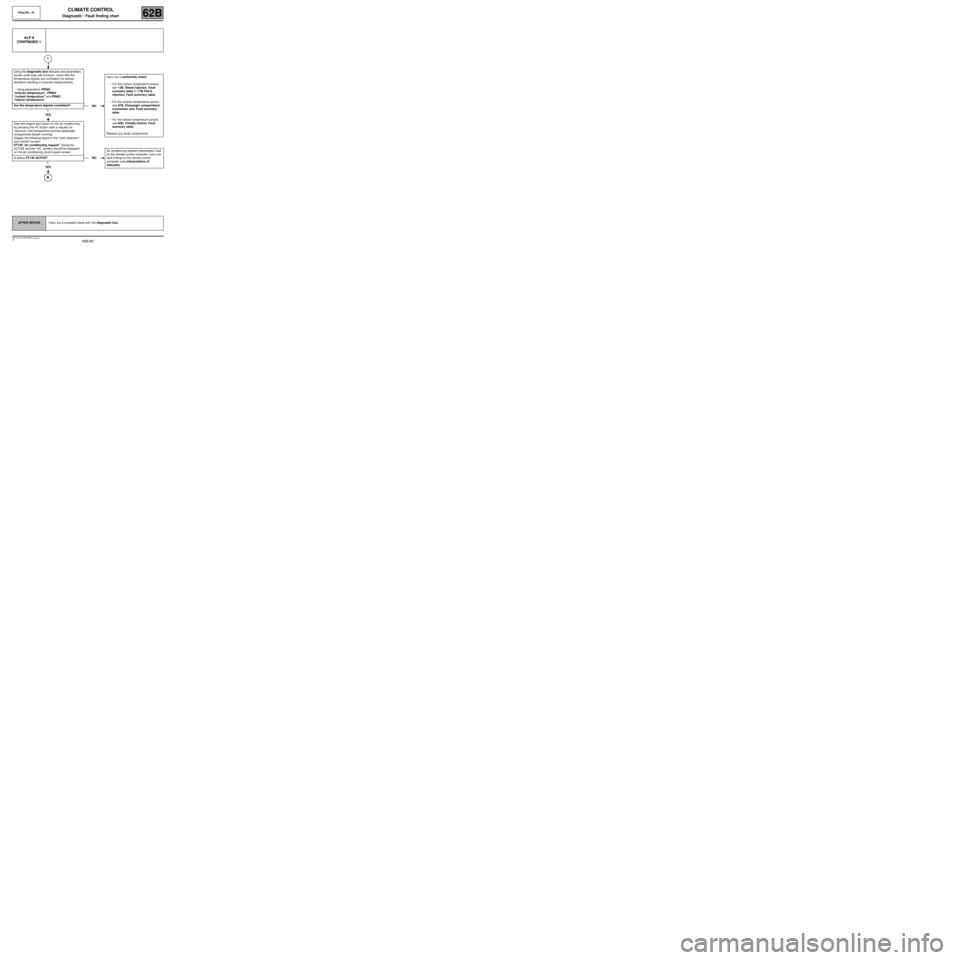
Using the diagnostic tool statuses and parameters
screen (cold loop sub-function), check that the
temperature signals are consistent (no sensor
deviation resulting in incorrect measurement).
–Using parameters PR002
"exterior temperature", PR064
"coolant temperature" and PR001
"interior temperature".
Are the temperature signals consistent?
YES
Start the engine and switch on the air conditioning
by pressing the AC button (with a request for
maximum cold temperature and the passenger
compartment blower running).
Display the following status in the “User selection”
sub-function screen:
ET140 "air conditioning request" should be
ACTIVE and the “AC” symbol should be displayed
on the air conditioning control panel screen.
Is status ET140 ACTIVE?
YES
NOCarry out a conformity check:
–For the coolant temperature sensor,
see 13B, Diesel injection, Fault
summary table or 17B Petrol
injection, Fault summary table.
–For the exterior temperature sensor,
see 87B, Passenger compartment
connection unit, Fault summary
table.
–For the interior temperature sensor,
see 62B, Climate control, Fault
summary table.
Replace any faulty components.
NOAir conditioning request interpretation fault
on the climate control computer. Carry out
fault finding on the climate control
computer (see interpretation of
statuses).
AFTER REPAIRCarry out a complete check with the diagnostic tool.
Page 81 of 99

62B-81
MR-413-X44-62B000$874_eng.mif
V1
Vdiag No.: 44CLIMATE CONTROL
Diagnostic - Fault finding chart62B
ALP 8
CONTINUED 2
With the engine running at idle speed, use the
diagnostic tool to check that the passenger
compartment central unit sends the start air
conditioning request to the injection computer.
Status ET030 Air conditioning request 2 should
display ACTIVE.
Is status ET030 "ACTIVE"?
YES
Using the diagnostic tool, display (injection cold
loop sub-function screen), the following statuses:
–ET004 Air conditioning authorised,
–ET088 Compressor activation request,
Is status ET004 "YES" and status ET088
"ACTIVE"
NO
Check that the injection computer is correctly configured. Status ET079 CLIMATE CONTROL PRESENT should
display YES (cold loop sub-function screen).
Is status ET079 YES?
YES
NOCheck that the UCH is correctly configured by
viewing the configuration reading LC013 Type
of air conditioning.
Should be “Climate control”
Reconfigure the UCH if necessary.
Check that the UCH is receiving the engine
operating status and passenger compartment
blower signals correctly (for manual air
conditioning). In the Cold Loop sub-function
screen, status ET142 "Engine operating
phase" should display “RUNNING” and status
ET015 "Passenger compartment blower"
should display “ACTIVE” and parameter
PR024 “Exterior temperature” is > 3˚C.
If the parameter and statuses are not correct,
carry out fault finding on the multiplex network
and UCH (interpretation of status ET015,
ET142 and parameter PR024).
YES
NO
Interpretation fault for status ET079, see
conformity check, cold loop sub-function:
–13B, Diesel injection,
–17B, Petrol injection.
AFTER REPAIRCarry out a complete check with the diagnostic tool.
Page 82 of 99

62B-82
MR-413-X44-62B000$874_eng.mif
V1
Vdiag No.: 44CLIMATE CONTROL
Diagnostic - Fault finding chart62B
ALP 8
CONTINUED 3
Carry out fault finding on the injection system to ensure that no fault is present (if faults are displayed by the injection
computer, engagement of the air conditioning may be inhibited). If there are present or stored faults, carry out the necessary
repairs (see 13B, Diesel injection or 17B, Petrol injection).
Check that the refrigerant fluid pressure is correct (neither too low nor too high) using the PR037 Refrigerant fluid
pressure parameter (see Conformity check, Cold loop sub-function).
Check that the engine cooling fan assembly is at speed 1 by
viewing the following status on the cold loop sub-function
screen:
- Status ET022 Low-speed fan assembly request should
display ACTIVE.
Note:
These statuses are not displayed by all types of injection
(see Conformity check, Cold loop sub-function).
Does the engine cooling fan operate at low speed?
YES
NO
Using the diagnostic tool, run command
AC154 Low speed fan assembly relay.
Does the engine cooling fan operate at
low speed?
NO YES
Connector of component 321 disconnected. Connect a test
light between connection 49L of component 321 and the
chassis earth and run command AC154 Low speed fan
assembly relay.
Does the test light illuminate?
YES NO
Carry out fault finding
on the injection
system (sub-function:
cold loop and engine
cooling for low speed
fan assembly
activation).
Measure the resistance of component 321, between connections
49L and 49B of component 321. If the resistance measured is
infinite, replace the fan assembly resistor (component 321).D
AFTER REPAIRCarry out a complete check with the diagnostic tool.
Page 84 of 99
62B-84
MR-413-X44-62B000$874_eng.mif
V1
Vdiag No.: 44CLIMATE CONTROL
Diagnostic - Fault finding chart62B
ALP 8
CONTINUED 5
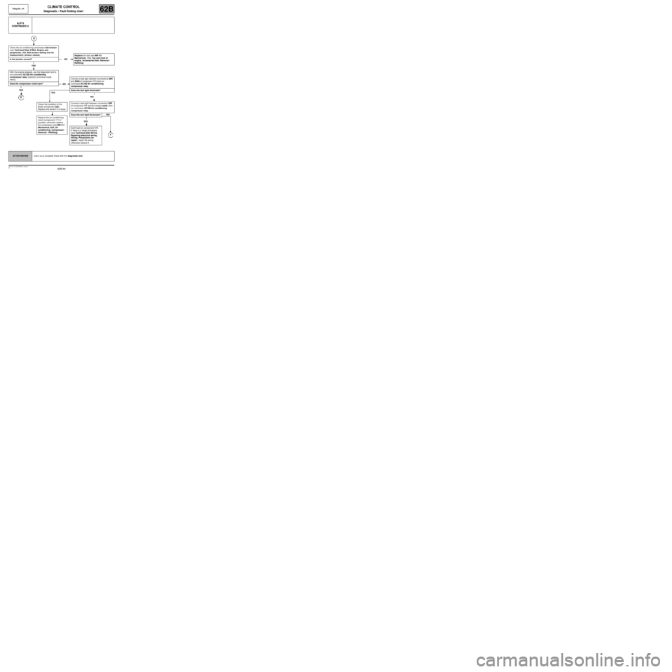
Check the air conditioning compressor belt tension
(see Technical Note 3786A, Engine and
peripherals, 10A, Belt tension setting tool Hz
measurement: tension values).
Is the tension correct?
YES
With the engine stopped, use the diagnostic tool to
run command AC180 Air conditioning
compressor relay (injection command mode
menu).
Does the compressor clutch jam?
YES
E
NOReplace the belt (see MR 411
Mechanical, 11A, Top and front of
engine, Accessories belt: Removal -
Refitting).
NOConnect a test light between connections 38R
and MAS of component 171 and run
command AC180 Air conditioning
compressor relay.
Does the test light illuminate?
NO
Connect a test light between connection 38R
of component 171 and the chassis earth, then
run command AC180 Air conditioning
compressor relay.
Does the test light illuminate?
YES
Earth fault on component 171.
If there is a repair procedure
(see Technical Note 6015A,
Repairing electrical wiring,
Wiring: Precautions for
repair), repair the wiring,
otherwise replace it.
NO
F
YES
Check the condition of the
diode (component 322).
Replace the diode if it is faulty.
Replace the air conditioning
clutch (component 171) if
possible, otherwise replace
the compressor (see MR 411
Mechanical, 62A, Air
conditioning, Compressor:
Removal - Refitting).
AFTER REPAIRCarry out a complete check with the diagnostic tool.
Page 86 of 99
62B-86
MR-413-X44-62B000$874_eng.mif
V1
Vdiag No.: 44CLIMATE CONTROL
Diagnostic - Fault finding chart62B
ALP 8
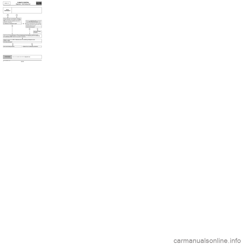
CONTINUED 7
2
With the engine warm and passenger compartment
ventilation operating, vary the position of the mixing
flap from the maximum hot position to the maximum
cold position and check subjectively that there is a
difference in temperature.
Is a difference in temperature noted?
YES
E
NOCarry out a conformity check on the mixing
motor (PR012 Mixing flap position). If the
conformity check does not reveal any faults,
look for a mechanical fault on the mixing flap
(condition of the motor ’s notched sector, flap
jammed inside the unit, etc.).
Is the fault still present?
YES NO
End of fault finding
procedure.
Check the cold loop by checking the condition of the pipes and ensuring that the air conditioning system
does not have any refrigerant leaks (see Technical Note 6001A, Air conditioning, 62A, Air conditioning,
Air conditioning: Check). Repair the faulty pipes or components.
Top up the refrigerant (see MR 411 Mechanical, 62A, Air conditioning, Refrigerant circuit:
Draining - Filling).
Is the fault still present?
NO YES
End of fault finding procedure. Replace the air conditioning compressor.
AFTER REPAIRCarry out a complete check with the diagnostic tool.
Page 87 of 99
62B-87
MR-413-X44-62B000$874_eng.mif
V1
Vdiag No.: 44CLIMATE CONTROL
Diagnostic - Fault finding chart62B
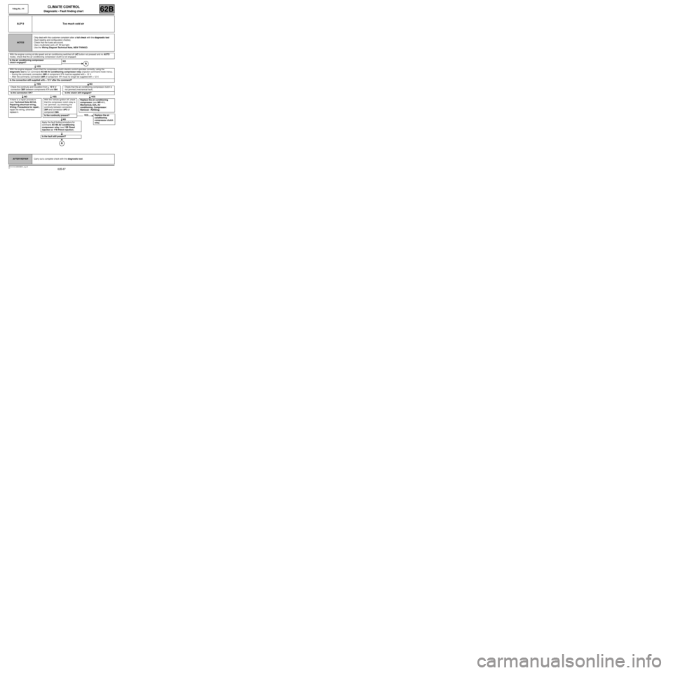
ALP 9 Too much cold air
NOTESOnly deal with this customer complaint after a full check with the diagnostic tool
(fault reading and configuration checks).
Check that the fuses are sound.
Use a multimeter and a 21 W test light.
Use the Wiring Diagram Technical Note, NEW TWINGO.
With the engine running at idle speed and air conditioning switched off (AC button not pressed and no AUTO
mode), check that the air conditioning compressor clutch is not engaged.
Is the air conditioning compressor
clutch engaged?NO
YES
With the engine stopped, check that the compressor clutch electric control operates correctly, using the
diagnostic tool to run command AC180 Air conditioning compressor relay (injection command mode menu).
–During the command, connection 38R of component 171 must be supplied with + 12 V.
–After the command, connection 38R of component 171 must no longer be supplied with + 12 V.
Is the connection still supplied with + 12 V after the command?
YES NO
Check the continuity and insulation from + 12 V of
connection 38R between components 171 and 584.Check that the air conditioning compressor clutch is
not jammed (mechanical fault).
Is the connection OK? Is the clutch still engaged?
NO YES YES
If there is a repair procedure
(see Technical Note 6015A,
Repairing electrical wiring,
Wiring: Precautions for repair),
repair the wiring, otherwise
replace it.With the vehicle ignition off, check
that the compressor clutch relay is
not “jammed”, by checking the
continuity between connection
38R and connection AP3 of
component 584.
Is the continuity present?
NO
Apply the fault finding procedure for
command AC180 Air conditioning
compressor relay (see 13B Diesel
injection or 17B Petrol injection).
Is the fault still present?
Replace the air conditioning
compressor (see MR 411,
Mechanical, 62A, Air
conditioning, Compressor:
Removal - Refitting).
YES Replace the air
conditioning
compressor clutch
relay.
AFTER REPAIRCarry out a complete check with the diagnostic tool.
Page 88 of 99
62B-88
MR-413-X44-62B000$874_eng.mif
V1
Vdiag No.: 44CLIMATE CONTROL
Diagnostic - Fault finding chart62B
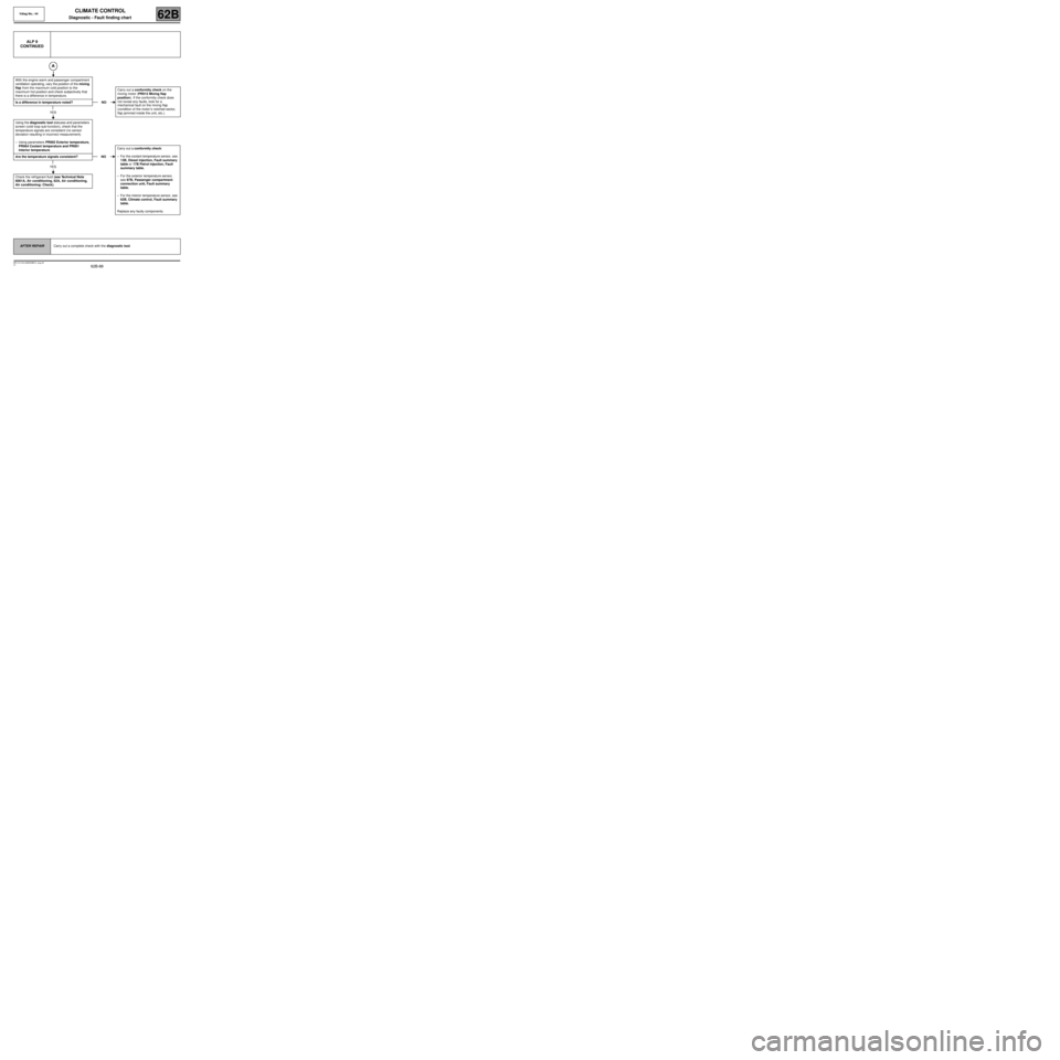
ALP 9
CONTINUED
With the engine warm and passenger compartment
ventilation operating, vary the position of the mixing
flap from the maximum cold position to the
maximum hot position and check subjectively that
there is a difference in temperature.
Is a difference in temperature noted?
YES
Using the diagnostic tool statuses and parameters
screen (cold loop sub-function), check that the
temperature signals are consistent (no sensor
deviation resulting in incorrect measurement).
–Using parameters PR002 Exterior temperature,
PR064 Coolant temperature and PR001
Interior temperature.
Are the temperature signals consistent?
YES
Check the refrigerant fluid (see Technical Note
6001A, Air conditioning, 62A, Air conditioning,
Air conditioning: Check).
NOCarry out a conformity check on the
mixing motor (PR012 Mixing flap
position). If the conformity check does
not reveal any faults, look for a
mechanical fault on the mixing flap
(condition of the motor ’s notched sector,
flap jammed inside the unit, etc.).
NOCarry out a conformity check:
–For the coolant temperature sensor, see
13B, Diesel injection, Fault summary
table or 17B Petrol injection, Fault
summary table.
–For the exterior temperature sensor,
see 87B, Passenger compartment
connection unit, Fault summary
table.
–For the interior temperature sensor, see
62B, Climate control, Fault summary
table.
Replace any faulty components.
AFTER REPAIRCarry out a complete check with the diagnostic tool.
Page 89 of 99
62B-89
MR-413-X44-62B000$920_eng.mif
V1
62B
CLIMATE CONTROL
Diagnostic - Fault finding chart
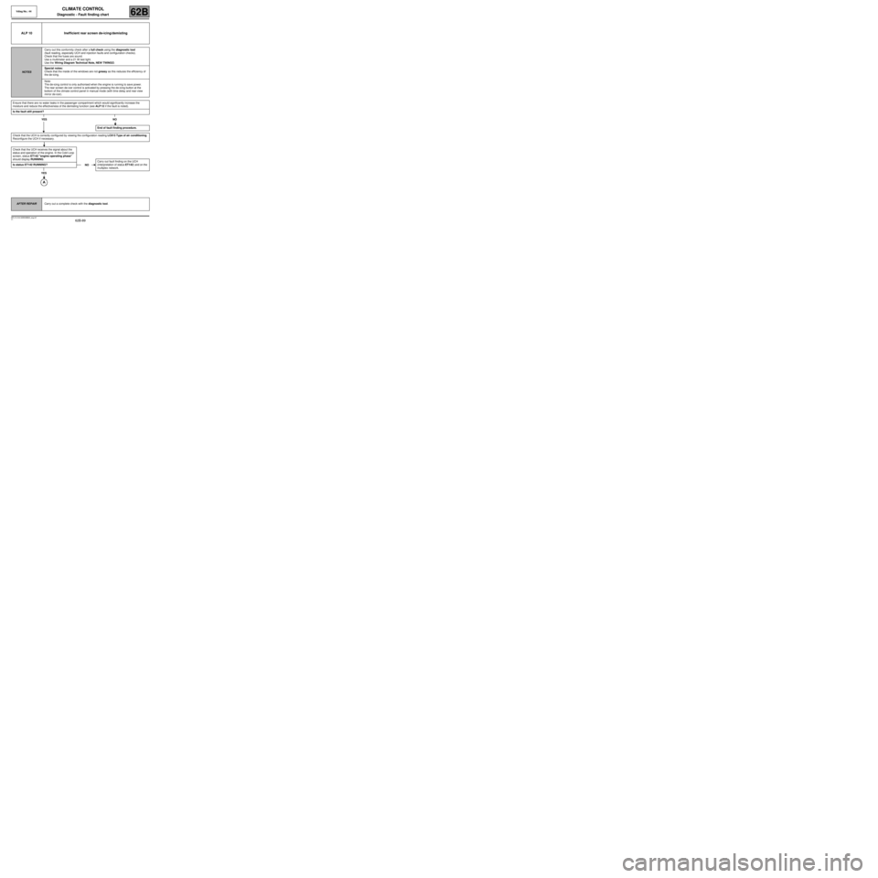
ALP 10 Inefficient rear screen de-icing/demisting
NOTESCarry out this conformity check after a full check using the diagnostic tool
(fault reading, especially UCH and injection faults and configuration checks).
Check that the fuses are sound.
Use a multimeter and a 21 W test light.
Use the Wiring Diagram Technical Note, NEW TWINGO.
Special notes:
Check that the inside of the windows are not greasy as this reduces the efficiency of
the de-icing.
Note:
The de-icing control is only authorised when the engine is running to save power.
The rear screen de-icer control is activated by pressing the de-icing button at the
bottom of the climate control panel in manual mode (with time delay and rear-view
mirror de-icer).
Ensure that there are no water leaks in the passenger compartment which would significantly increase the
moisture and reduce the effectiveness of the demisting function (see ALP 12 if the fault is noted).
Is the fault still present?
YES NO
Check that the UCH is correctly configured by viewing the configuration reading LC013 Type of air conditioning.
Reconfigure the UCH if necessary.
Check that the UCH receives the signal about the
status and operation of the engine. In the Cold Loop
screen, status ET142 "engine operating phase"
should display RUNNING.
Is status ET142 RUNNING?
YES
End of fault finding procedure.
NOCarry out fault finding on the UCH
(interpretation of status ET142) and on the
multiplex network.
AFTER REPAIRCarry out a complete check with the diagnostic tool.
Vdiag No.: 44
MR-413-X44-62B000$920_eng.mif