RENAULT TWINGO RS 2009 2.G Heating And Air Conditioning - Climate Control Manual PDF
Manufacturer: RENAULT, Model Year: 2009, Model line: TWINGO RS, Model: RENAULT TWINGO RS 2009 2.GPages: 99
Page 71 of 99
62B-71
MR-413-X44-62B000$828_eng.mif
V1
Vdiag No.: 44CLIMATE CONTROL
Diagnostic - Fault finding chart62B
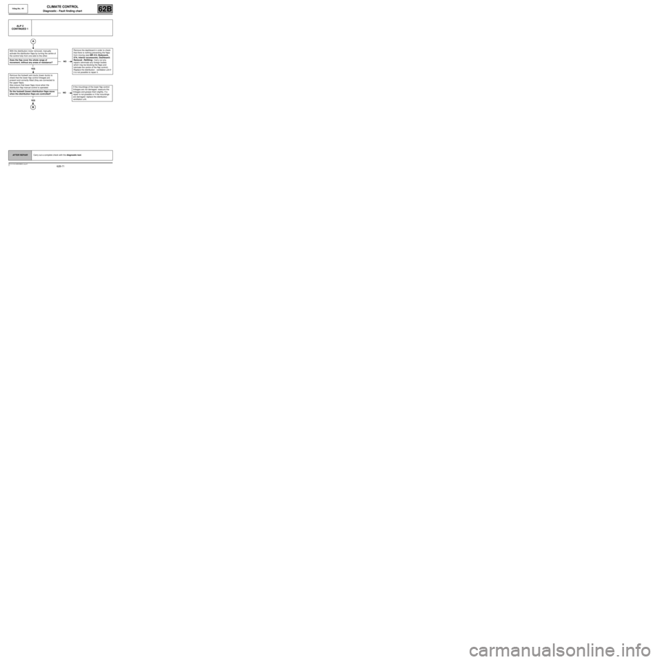
ALP 2
CONTINUED 1
With the distribution motor removed, manually
activate the distribution flaps by turning the centre of
the control fully from one side to the other.
Does the flap cover the whole range of
movement, without any areas of resistance?
YES
Remove the footwell vent ducts (lower ducts) to
check that the lower flap control linkages are
present and correctly fitted (they are connected to
the upper flaps).
Also ensure that lower flaps move when the
distribution flap manual control is operated.
Do the footwell (lower) distribution flaps move
when the distribution flaps are controlled?
YES
NORemove the dashboard in order to check
that there is nothing preventing the flaps
from moving (see MR 412, Bodywork,
57A, Interior accessories, Dashboard:
Removal - Refitting). Carry out any
repairs (eliminate any foreign bodies
which may be blocking the flaps and
lubricate the centre of the flap control).
Replace the distribution - ventilation unit if
it is not possible to repair it.
NOIf the mountings of the lower flap control
linkages are not damaged: resecure the
linkages and grease them slightly. If a
repair is not possible or if the mountings
are damaged: replace the distribution -
ventilation unit.
AFTER REPAIRCarry out a complete check with the diagnostic tool.
Page 72 of 99
62B-72
MR-413-X44-62B000$828_eng.mif
V1
Vdiag No.: 44CLIMATE CONTROL
Diagnostic - Fault finding chart62B
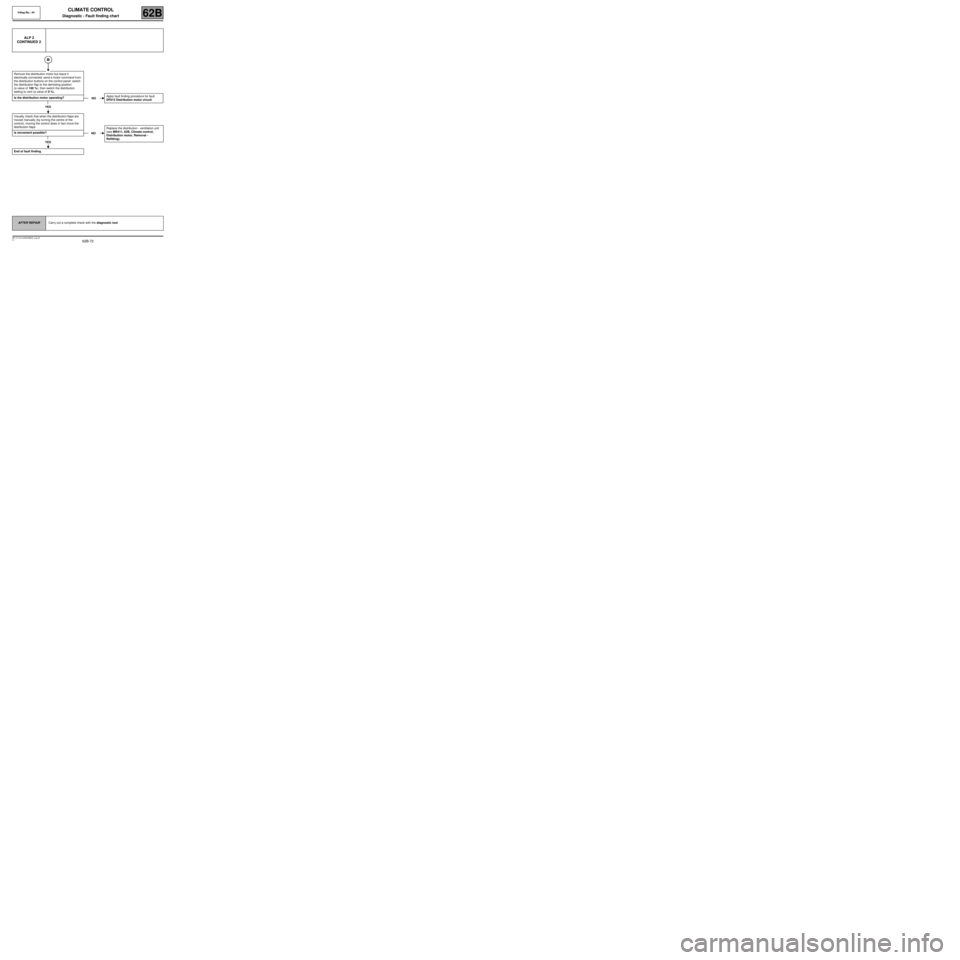
ALP 2
CONTINUED 2
Remove the distribution motor but leave it
electrically connected, send a motor command from
the distribution buttons on the control panel: switch
the distribution flap to the demisting position
(a value of 100 %), then switch the distribution
setting to vent (a value of 0 %).
Is the distribution motor operating?
YES
Visually check that when the distribution flaps are
moved manually (by turning the centre of the
control), moving the control does in fact move the
distribution flaps.
Is movement possible?
YES
End of fault finding.
NOApply fault finding procedure for fault
DF012 Distribution motor circuit.
NOReplace the distribution - ventilation unit
(see MR411, 62B, Climate control,
Distribution motor, Removal -
Refitting).
AFTER REPAIRCarry out a complete check with the diagnostic tool.
Page 73 of 99
62B-73
MR-413-X44-62B000$828_eng.mif
V1
Vdiag No.: 44CLIMATE CONTROL
Diagnostic - Fault finding chart62B
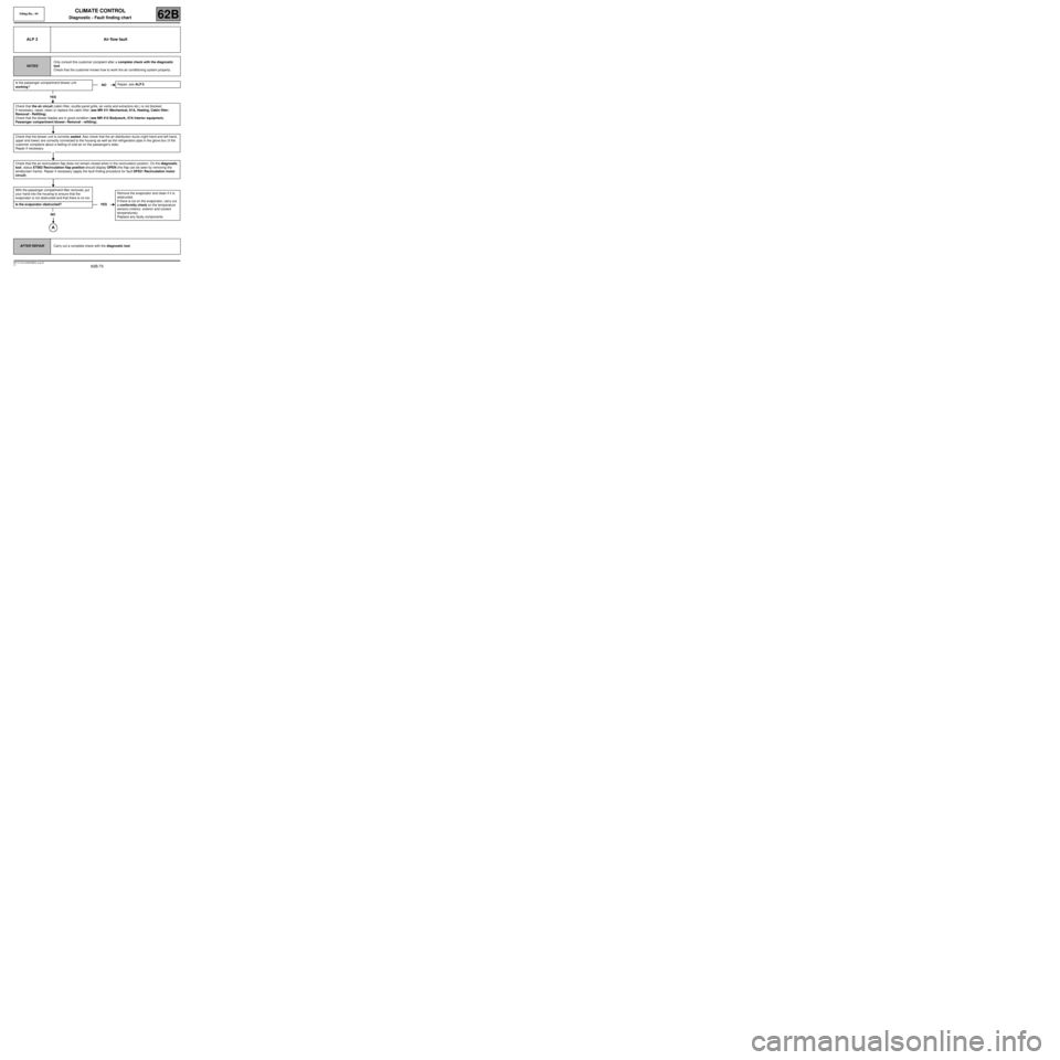
ALP 3 Air flow fault
NOTESOnly consult this customer complaint after a complete check with the diagnostic
tool.
Check that the customer knows how to work the air conditioning system properly.
Is the passenger compartment blower unit
working?
YES
Check that the air circuit (cabin filter, scuttle panel grille, air vents and extractors etc.) is not blocked.
If necessary, repair, clean or replace the cabin filter (see MR 411 Mechanical, 61A, Heating, Cabin filter:
Removal - Refitting).
Check that the blower blades are in good condition (see MR 412 Bodywork, 57A Interior equipment,
Passenger compartment blower: Removal - refitting).
Check that the blower unit is correctly sealed. Also check that the air distribution ducts (right-hand and left-hand,
upper and lower) are correctly connected to the housing as well as the refrigeration pipe in the glove box (if the
customer complains about a feeling of cold air on the passenger's side).
Repair if necessary.
Check that the air recirculation flap does not remain closed when in the recirculation position. On the diagnostic
tool, status ET062 Recirculation flap position should display OPEN (the flap can be seen by removing the
windscreen frame). Repair if necessary (apply the fault finding procedure for fault DF021 Recirculation motor
circuit).
With the passenger compartment filter removed, put
your hand into the housing to ensure that the
evaporator is not obstructed and that there is no ice.
Is the evaporator obstructed?
NO
NORepair, see ALP 5.
YESRemove the evaporator and clean if it is
obstructed.
If there is ice on the evaporator, carry out
a conformity check on the temperature
sensors (interior, exterior and coolant
temperatures).
Replace any faulty components.
AFTER REPAIRCarry out a complete check with the diagnostic tool.
Page 74 of 99
62B-74
MR-413-X44-62B000$828_eng.mif
V1
Vdiag No.: 44CLIMATE CONTROL
Diagnostic - Fault finding chart62B
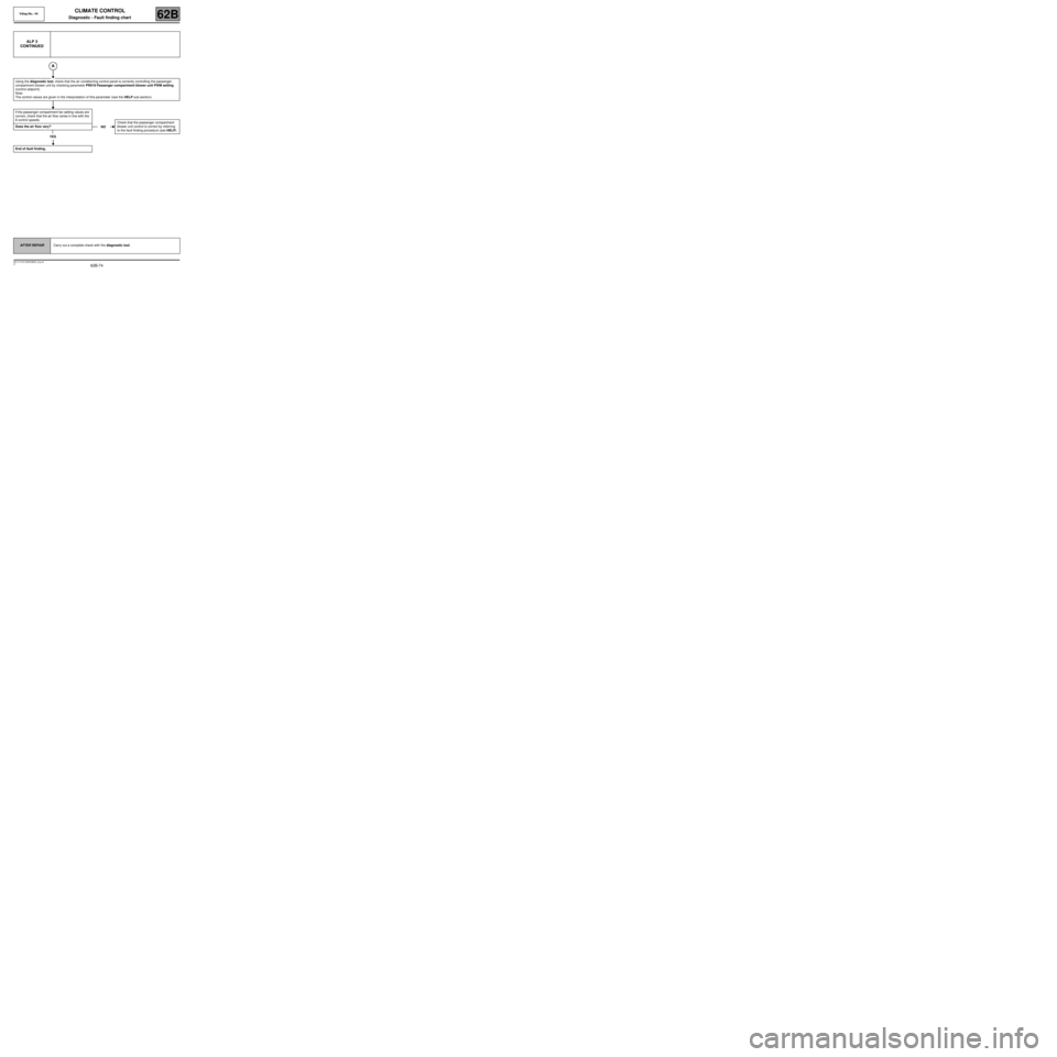
ALP 3
CONTINUED
Using the diagnostic tool, check that the air conditioning control panel is correctly controlling the passenger
compartment blower unit by checking parameter PR019 Passenger compartment blower unit PWM setting
(control setpoint).
Note:
The control values are given in the interpretation of this parameter (see the HELP sub-section).
If the passenger compartment fan setting values are
correct, check that the air flow varies in line with the
8 control speeds.
Does the air flow vary?
YES
End of fault finding.
NOCheck that the passenger compartment
blower unit control is correct by referring
to the fault finding procedure (see HELP).
AFTER REPAIRCarry out a complete check with the diagnostic tool.
Page 75 of 99
62B-75
MR-413-X44-62B000$828_eng.mif
V1
Vdiag No.: 44CLIMATE CONTROL
Diagnostic - Fault finding chart62B
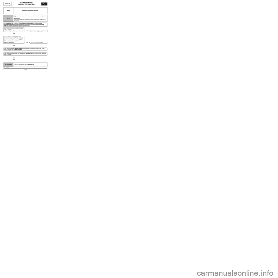
ALP 4 Inefficient windscreen demisting
NOTESOnly consult this customer complaint after a complete check with the diagnostic
tool.
Special notes:
Check that the inside of the windows are not greasy, as this lowers the efficiency of
the demister.
Use the diagnostic tool to check that the computer is correctly configured by reading the LC046
GEOGRAPHICAL ZONE configuration. If necessary, reconfigure the computer (CF024 GEOGRAPHICAL
ZONE) and check that the windscreen demisting operates correctly.
Check that the air extraction vents are not blocked.
Repair if necessary.
Is the fault still present?
YES
Check that there is no water leakage in the
passenger compartment which would significantly
increase the humidity and reduce the efficiency of
the demisting. Repair if necessary (see ALP12
Water in the passenger compartment).
Is the fault still present?
YES
Check that the compressor operates correctly by switching on the air conditioning (press the “AC” button).
Repair if necessary (see ALP8 NO COLD AIR).
Check that the condensation (water from the evaporator) evacuation ring is not obstructed (under the vehicle).
Repair if necessary.
NO
End of fault finding procedure.
NO End of fault finding procedure.
AFTER REPAIRCarry out a complete check with the diagnostic tool.
CLIM_V44_ALP4
Page 76 of 99
62B-76
MR-413-X44-62B000$828_eng.mif
V1
Vdiag No.: 44CLIMATE CONTROL
Diagnostic - Fault finding chart62B
ALP 4
CONTINUED
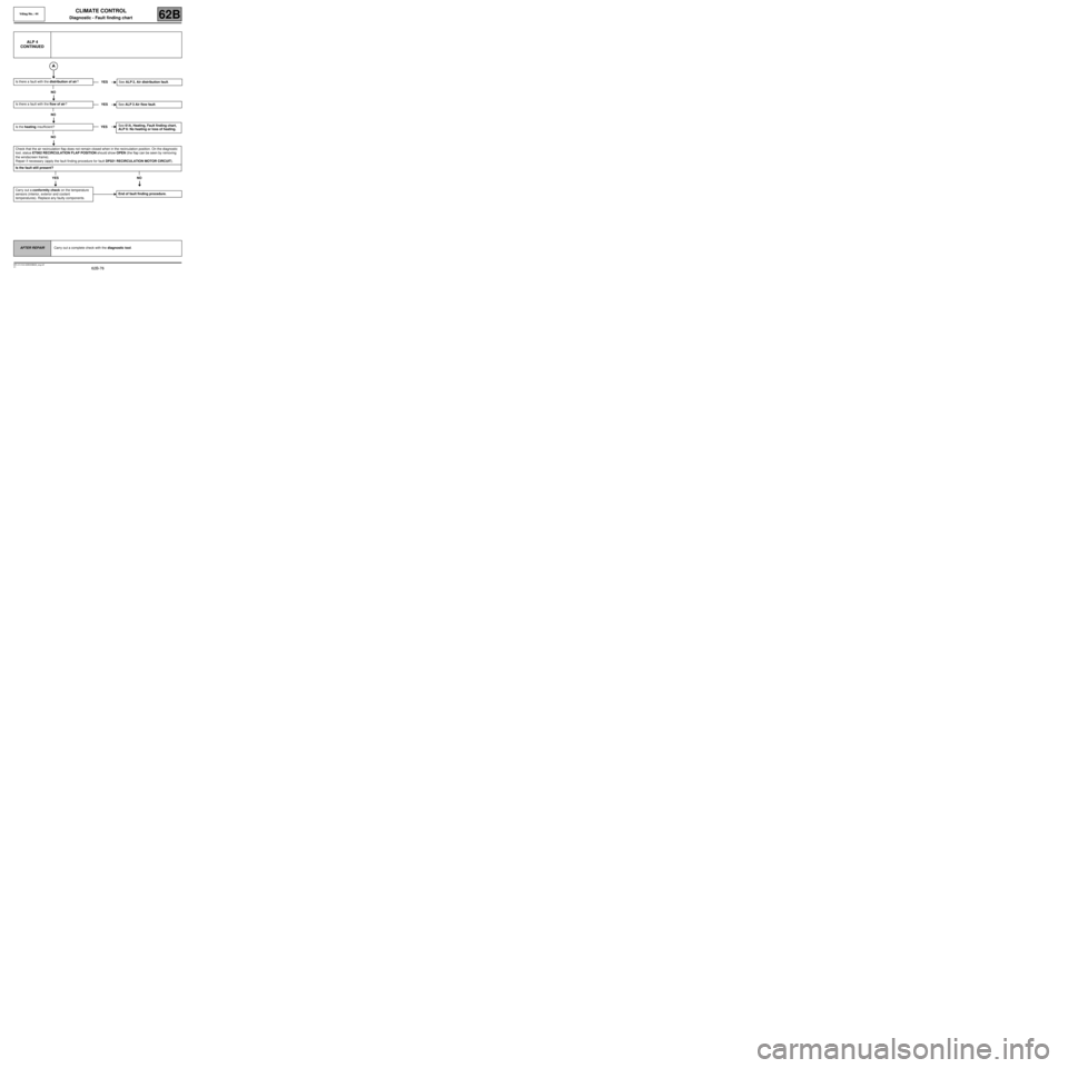
Is there a fault with the distribution of air?
NO
Is there a fault with the flow of air?
NO
Is the heating insufficient?
NO
Check that the air recirculation flap does not remain closed when in the recirculation position. On the diagnostic
tool, status ET062 RECIRCULATION FLAP POSITION should show OPEN (the flap can be seen by removing
the windscreen frame).
Repair if necessary (apply the fault finding procedure for fault DF021 RECIRCULATION MOTOR CIRCUIT).
Is the fault still present?
YES NO
Carry out a conformity check on the temperature
sensors (interior, exterior and coolant
temperatures). Replace any faulty components.YESSee ALP 2, Air distribution fault.
YESSee ALP 3 Air flow fault.
YESSee 61A, Heating, Fault finding chart,
ALP 6: No heating or loss of heating.
End of fault finding procedure.
AFTER REPAIRCarry out a complete check with the diagnostic tool.
Page 77 of 99
62B-77
MR-413-X44-62B000$828_eng.mif
V1
Vdiag No.: 44CLIMATE CONTROL
Diagnostic - Fault finding chart62B
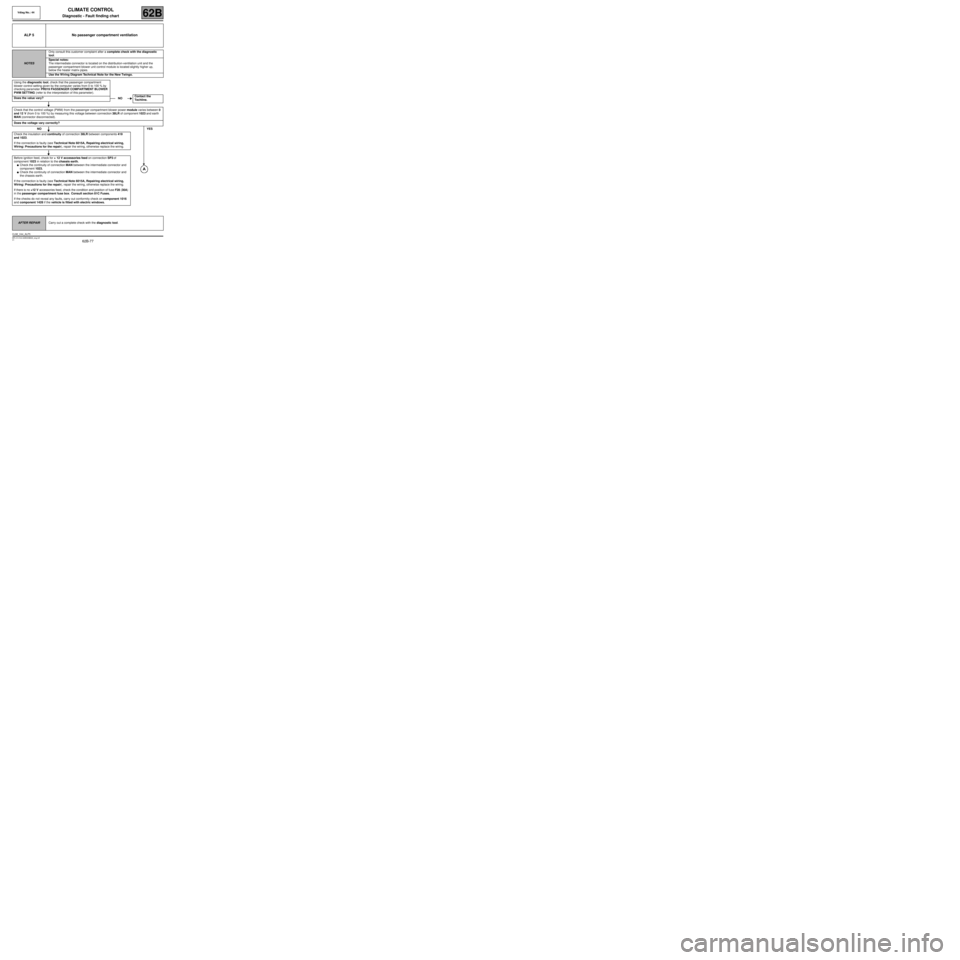
ALP 5 No passenger compartment ventilation
NOTESOnly consult this customer complaint after a complete check with the diagnostic
tool.
Special notes:
The intermediate connector is located on the distribution-ventilation unit and the
passenger compartment blower unit control module is located slightly higher up,
below the heater matrix pipes.
Use the W iring Diagram Technical Note for the New Twingo.
Using the diagnostic tool, check that the passenger compartment
blower control setting given by the computer varies from 0 to 100 % by
checking parameter PR019 PASSENGER COMPARTMENT BLOWER
PWM SETTING (refer to the interpretation of this parameter).
Does the value vary?
Check that the control voltage (PWM) from the passenger compartment blower power module varies between 0
and 12 V (from 0 to 100 %) by measuring this voltage between connection 38LR of component 1023 and earth
MAN (connector disconnected).
Does the voltage vary correctly?
NOYES
Check the insulation and continuity of connection 38LR between components 419
and 1023.
If the connection is faulty (see Technical Note 6015A, Repairing electrical wiring,
Wiring: Precautions for the repair), repair the wiring, otherwise replace the wiring.
Before ignition feed, check for + 12 V accessories feed on connection SP3 of
component 1023 in relation to the chassis earth.
●Check the continuity of connection MAN between the intermediate connector and
component 1023.
●Check the continuity of connection MAN between the intermediate connector and
the chassis earth.
If the connection is faulty (see Technical Note 6015A, Repairing electrical wiring,
Wiring: Precautions for the repair), repair the wiring, otherwise replace the wiring.
If there is no +12 V accessories feed, check the condition and position of fuse F28 (30A)
in the passenger compartment fuse box. Consult section 81C Fuses.
If the checks do not reveal any faults, carry out conformity check on component 1016
and component 1428 if the vehicle is fitted with electric windows.
NOContact the
Techline.
AFTER REPAIRCarry out a complete check with the diagnostic tool.
CLIM_V44_ALP5
Page 78 of 99
62B-78
MR-413-X44-62B000$828_eng.mif
V1
CLIMATE CONTROL
Diagnostic - Fault finding chart
Vdiag No.: 44
62B
ALP 5
CONTINUED
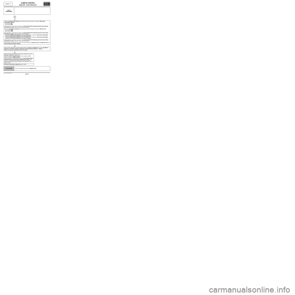
Check the insulation and continuity of the following connections between component 1023 and the
intermediate connector:
●connection SP3
●connection MAN
If the connection or connections are faulty (see Technical Note 6015A, Repairing electrical wiring, Wiring:
Precautions for repair), repair the wiring, otherwise replace it.
Check the insulation and continuity of the following connections between component 1023 and 1156:
●connection 38DB
●connection 38DA
If the connection or connections are faulty (see Technical Note 6015A, Repairing electrical wiring, Wiring:
Precautions for repair), repair the wiring, otherwise replace it.
–Check the insulation and continuity of connection SP3 between component 1428 and the intermediate
connector if the vehicle is fitted with front electric windows.
–Check the insulation and continuity of connection SP3 between component 1016 and the intermediate
connector if the vehicle is fitted with front manual windows.
If the connection or connections are faulty (see Technical Note 6015A, Repairing electrical wiring, Wiring:
Precautions for repair), repair the wiring, otherwise replace it.
If the checks do not reveal any faults, carry out conformity check on component 1016 and component 1428 if the
vehicle is fitted with electric windows.
Check that the passenger compartment blower blade is not broken or separated from its shaft (see MR 412
Bodywork, 57A Interior equipment, Passenger compartment blower: Removal - refitting).
Replace the passenger compartment blower if necessary.
With the connector disconnected, measure the resistance value of the
passenger compartment blower motor:
Check the resistance (approximately 0.180 Ω of component 1156
between connections 38DB and 38DA.
If the connection or connections are faulty (see Technical Note 6015A,
Repairing electrical wiring, Wiring: Precautions for repair), repair
the wiring, otherwise replace the passenger compartment blower.
Replace the passenger compartment blower if the resistance is zero or
equal to infinity.
If the fault is still present, replace the power module.
AFTER REPAIRCarry out a complete check with the diagnostic tool.
Page 79 of 99
62B-79
MR-413-X44-62B000$874_eng.mif
V1
62B
CLIMATE CONTROL
Diagnostic - Fault finding chart
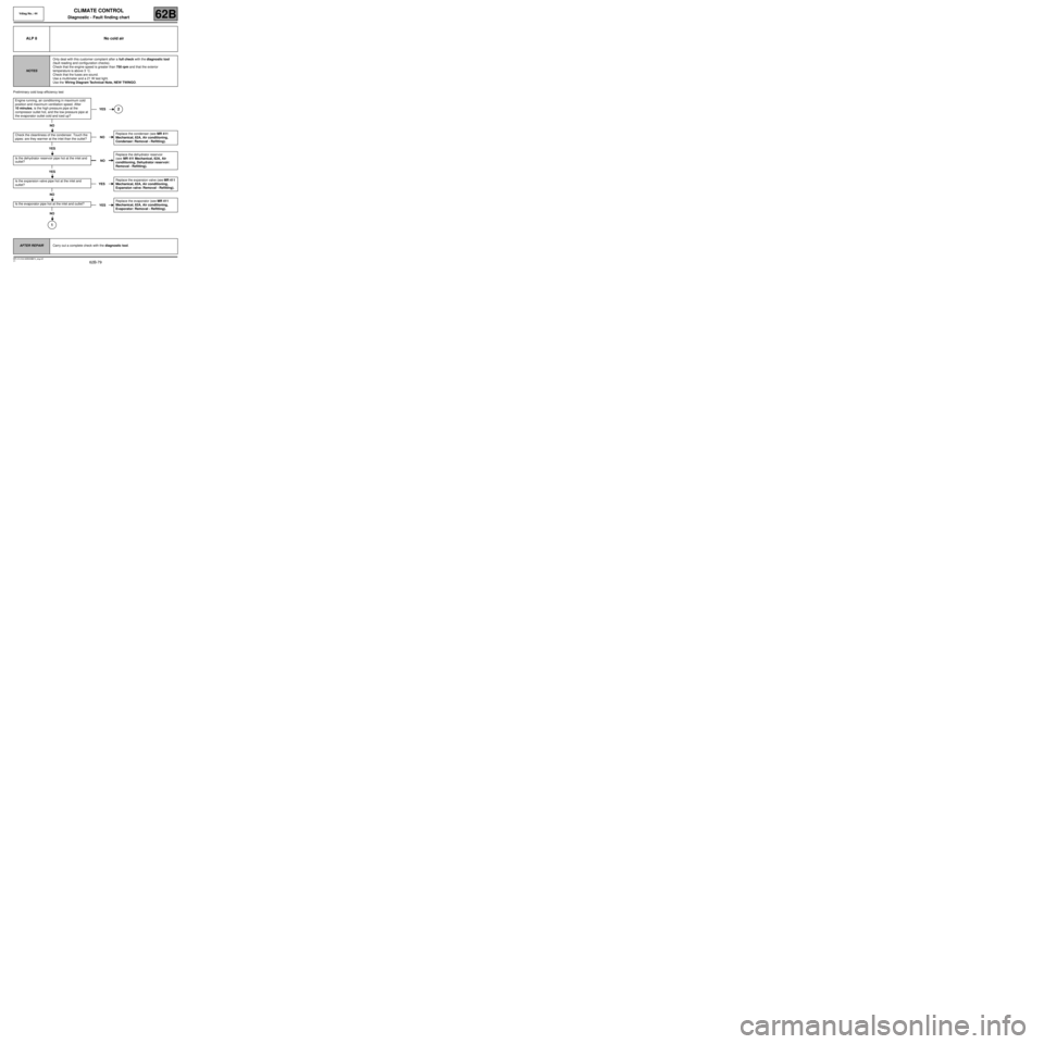
Preliminary cold loop efficiency test
ALP 8 No cold air
NOTESOnly deal with this customer complaint after a full check with the diagnostic tool
(fault reading and configuration checks).
Check that the engine speed is greater than 750 rpm and that the exterior
temperature is above 3 ˚C.
Check that the fuses are sound.
Use a multimeter and a 21 W test light.
Use the Wiring Diagram Technical Note, NEW TWINGO.
Engine running, air conditioning in maximum cold
position and maximum ventilation speed. After
10 minutes, is the high pressure pipe at the
compressor outlet hot, and the low pressure pipe at
the evaporator outlet cold and iced up?
NO
Check the cleanliness of the condenser. Touch the
pipes: are they warmer at the inlet than the outlet?
YES
Is the dehydrator reservoir pipe hot at the inlet and
outlet?
YES
Is the expansion valve pipe hot at the inlet and
outlet?
NO
Is the evaporator pipe hot at the inlet and outlet?
NO
1
YES2
NOReplace the condenser (see MR 411
Mechanical, 62A, Air conditioning,
Condenser: Removal - Refitting).
NOReplace the dehydrator reservoir
(see MR 411 Mechanical, 62A, Air
conditioning, Dehydrator reservoir:
Removal - Refitting).
YESReplace the expansion valve (see MR 411
Mechanical, 62A, Air conditioning,
Expansion valve: Removal - Refitting).
YESReplace the evaporator (see MR 411
Mechanical, 62A, Air conditioning,
Evaporator: Removal - Refitting).
AFTER REPAIRCarry out a complete check with the diagnostic tool.
Vdiag No.: 44
MR-413-X44-62B000$874_eng.mif
Page 80 of 99
62B-80
MR-413-X44-62B000$874_eng.mif
V1
Vdiag No.: 44CLIMATE CONTROL
Diagnostic - Fault finding chart62B
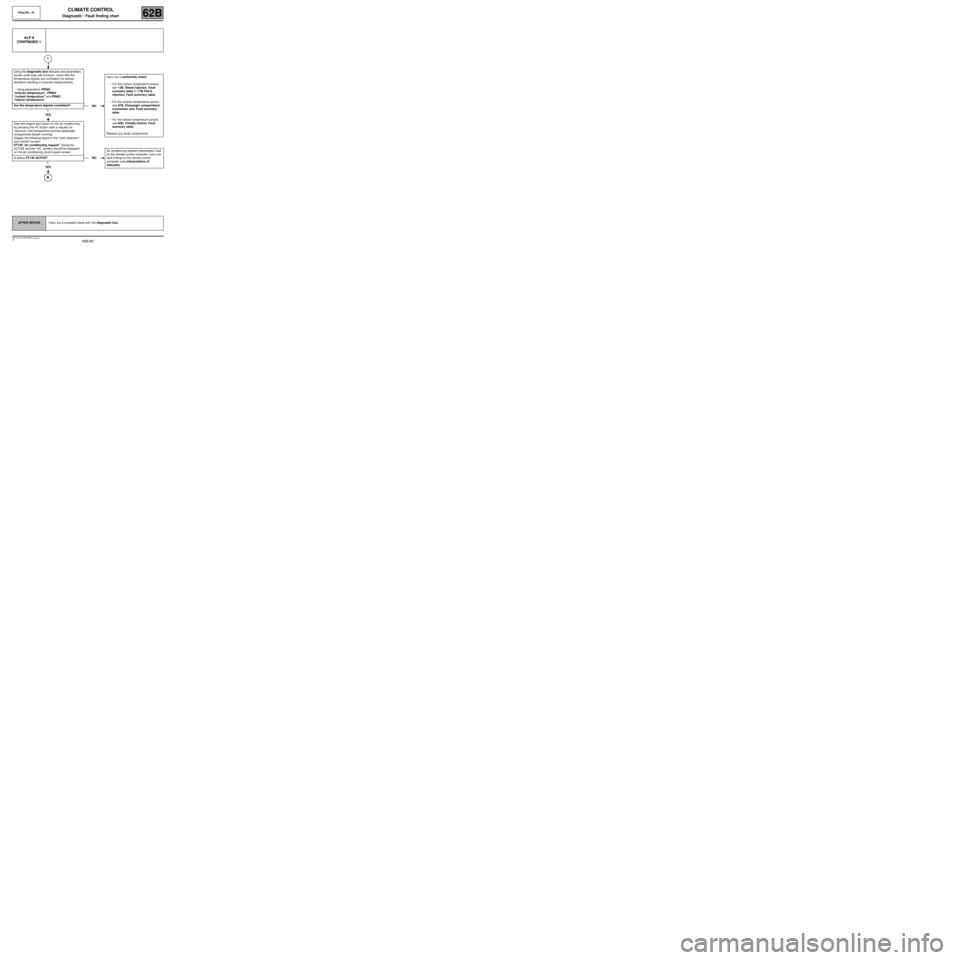
ALP 8
CONTINUED 1
1
Using the diagnostic tool statuses and parameters
screen (cold loop sub-function), check that the
temperature signals are consistent (no sensor
deviation resulting in incorrect measurement).
–Using parameters PR002
"exterior temperature", PR064
"coolant temperature" and PR001
"interior temperature".
Are the temperature signals consistent?
YES
Start the engine and switch on the air conditioning
by pressing the AC button (with a request for
maximum cold temperature and the passenger
compartment blower running).
Display the following status in the “User selection”
sub-function screen:
ET140 "air conditioning request" should be
ACTIVE and the “AC” symbol should be displayed
on the air conditioning control panel screen.
Is status ET140 ACTIVE?
YES
NOCarry out a conformity check:
–For the coolant temperature sensor,
see 13B, Diesel injection, Fault
summary table or 17B Petrol
injection, Fault summary table.
–For the exterior temperature sensor,
see 87B, Passenger compartment
connection unit, Fault summary
table.
–For the interior temperature sensor,
see 62B, Climate control, Fault
summary table.
Replace any faulty components.
NOAir conditioning request interpretation fault
on the climate control computer. Carry out
fault finding on the climate control
computer (see interpretation of
statuses).
AFTER REPAIRCarry out a complete check with the diagnostic tool.