dashboard RENAULT TWINGO RS 2009 2.G Heating And Air Conditioning - Climate Control Workshop Manual
[x] Cancel search | Manufacturer: RENAULT, Model Year: 2009, Model line: TWINGO RS, Model: RENAULT TWINGO RS 2009 2.GPages: 99
Page 8 of 99
62B-8
MR-413-X44-62B000$092_eng.mif
V1
62B
CLIMATE CONTROL
Fault finding - List and location of components
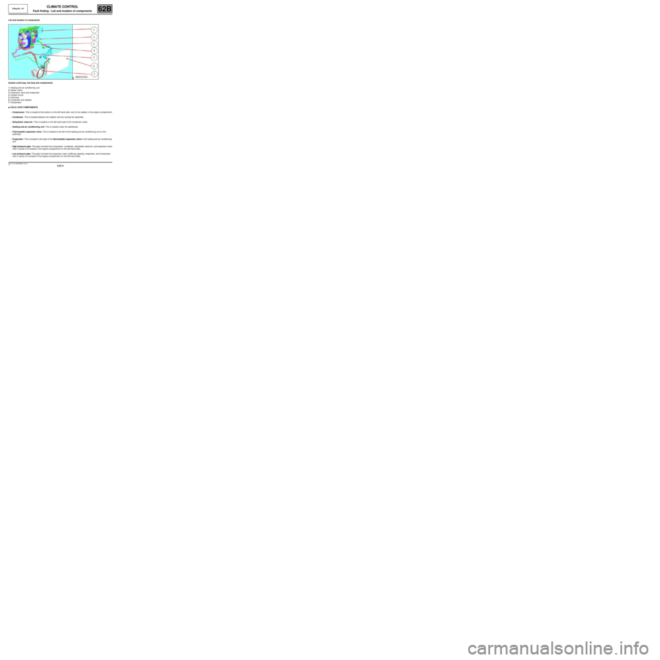
List and location of components
System (cold loop, hot loop and components)
1Heating and air conditioning unit
2Heater matrix
3Expansion valve and evaporator
4Coolant circuit
5Cold loop
6Condenser and radiator
7Compressor
●COLD LOOP COMPONENTS
–Compressor: This is located at the bottom on the left-hand side, next to the radiator in the engine compartment.
–Condenser: This is located between the radiator and the cooling fan assembly.
–Dehydrator reservoir: This is located on the left-hand side of the condenser outlet.
–Heating and air conditioning unit: This is located under the dashboard.
–Thermostatic expansion valve: This is located to the left of the heating and air conditioning unit on the
bulkhead.
–Evaporator: This is located to the right of the thermostatic expansion valve in the heating and air conditioning
unit.
–High pressure pipe: This pipe connects the compressor, condenser, dehydrator reservoir, and expansion valve
inlet in series (it is located in the engine compartment on the left-hand side).
–Low pressure pipe: This pipe connects the expansion valve, buffering capacity, evaporator, and compressor
inlet in series (it is located in the engine compartment on the left-hand side).
Vdiag No.: 44
MR-413-X44-62B000$092_eng.mif
Page 9 of 99
62B-9
MR-413-X44-62B000$092_eng.mif
V1
CLIMATE CONTROL
Fault finding - List and location of components
Vdiag No.: 44
62B
●HEATING COMPONENTS
–Heater matrix: This is located at the bottom of the heating and air conditioning unit.
–Passenger compartment heating resistors: These are located at the bottom of the heater matrix on the
driver's side (depending on the equipment).
●SENSOR
–Interior temperature sensor: This is located on the interior rear-view mirror.
●ACTUATORS
–Air distribution flap: This is located in the heating and air conditioning unit.
–Air mixing flap: This is located in the heating and air conditioning unit.
–Recirculation flap: This is located behind the dashboard.
–Flap motors: These are located close to the flaps.
●OTHERS
–Passenger compartment blower unit: This is located in the heating and air conditioning unit.
–Cooling fan assembly: This is located in the front panel of the vehicle, in front of the condenser.
–Climate control computer: This is located in the control panel.
–Air pipes: Theses are located under the dashboard.
Page 26 of 99
62B-26
MR-413-X44-62B000$414_eng.mif
V1
CLIMATE CONTROL
Fault finding - Interpretation of faults
Vdiag No.: 44
62B
DF007
PRESENT
OR
STOREDINTERIOR TEMPERATURE SENSOR CIRCUIT
CC.0 : Short circuit to earth
CO.1 : Short circuit or open circuit to + 12 V
NOTESConditions for running fault finding on a present or stored fault:
Apply this fault finding procedure if the fault reappears as present or stored after the
ignition is switched on and air conditioning activation is requested with the engine
running.
Special notes:
The interior temperature sensor is located at the top of the roof in the unit under the
rear view mirror.
Use the Wiring Diagram Technical Note for the New Twingo.
Check the connection and condition (possible wiring damage) of the connector of component 1872.
If the connector is faulty (see Technical Note 6015A, Repairing electrical wiring, Wiring: Precautions for the
repair), repair the connector, otherwise replace the wiring.
With connector A of component 419 and connector of union R301 disconnected, check the insulation and
continuity of the following connections between components R301 (dashboard/interior lights intermediate union)
and 419.
●connection 38JN
●connection 38GZ
If the connection or connections are faulty (see Technical Note 6015A, Repairing electrical wiring, Wiring:
Precautions for repair), repair the wiring, otherwise replace it.
With the connector of component 1872 disconnected, check the insulation and continuity of the following
connections between components R301 (dashboard/interior lights intermediate union) and 1872.
●connection 38JN
●connection 38GZ
If the connection or connections are faulty (see Technical Note 6015A, Repairing electrical wiring, Wiring:
Precautions for repair), repair the wiring, otherwise replace it.
Check the insulation of connections 38JN and 38GZ of component 1872.
If the connection or connections are faulty and there is a repair procedure (see Technical Note 6015A, Electrical
wiring repair, Wiring: Precautions for repair), repair the wiring, otherwise replace it.
Check the resistance of component 1872 between connections 38JN and 38GZ.
Replace the sensor if the resistance is not 10 kΩΩ Ω Ω
± 500 ΩΩ Ω Ω
at 25 ˚C. For more details, consult the electrical
specifications of the sensor according to the temperature (see Help).
If the fault is still present, contact the Techline.
AFTER REPAIRClear the stored faults.
Follow the instructions to confirm repair.
Deal with any other faults.
CLIM_V44_DF007
Page 65 of 99
62B-65
MR-413-X44-62B000$736_eng.mif
V1
CLIMATE CONTROL
Fault finding - Interpretation of commands
Vdiag No.: 44
62B
AC006
AC007
DISTRIBUTION MOTOR: AIR VENTS
DISTRIBUTION MOTOR: DE-ICING
NOTESNOTE
The flap is located under the dashboard.
This command is used to activate the ventilation/de-icing distribution flap to check that it is working.
Switch on the ignition, and issue a passenger compartment ventilation request (via the driver's control panel).
Run command AC007 and check that the air comes out by the windscreen.
Run command AC006 and check that the air comes out of the front air vents.
If the command does not operate as indicated, check the air distribution conformity (see ALP 2 Air distribution
fault).
AFTER REPAIRCheck that the air conditioning function operates correctly.
CLIM_V44_AC006 / CLIM_V44_AC007
Page 71 of 99
62B-71
MR-413-X44-62B000$828_eng.mif
V1
Vdiag No.: 44CLIMATE CONTROL
Diagnostic - Fault finding chart62B
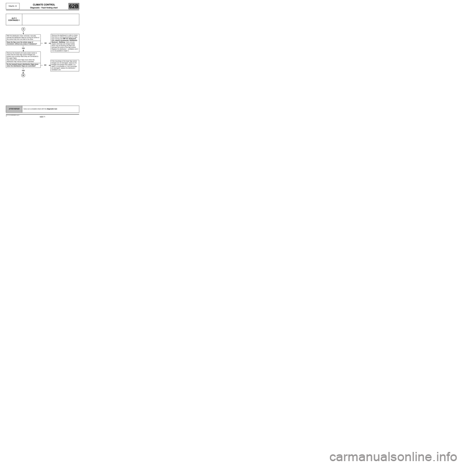
ALP 2
CONTINUED 1
With the distribution motor removed, manually
activate the distribution flaps by turning the centre of
the control fully from one side to the other.
Does the flap cover the whole range of
movement, without any areas of resistance?
YES
Remove the footwell vent ducts (lower ducts) to
check that the lower flap control linkages are
present and correctly fitted (they are connected to
the upper flaps).
Also ensure that lower flaps move when the
distribution flap manual control is operated.
Do the footwell (lower) distribution flaps move
when the distribution flaps are controlled?
YES
NORemove the dashboard in order to check
that there is nothing preventing the flaps
from moving (see MR 412, Bodywork,
57A, Interior accessories, Dashboard:
Removal - Refitting). Carry out any
repairs (eliminate any foreign bodies
which may be blocking the flaps and
lubricate the centre of the flap control).
Replace the distribution - ventilation unit if
it is not possible to repair it.
NOIf the mountings of the lower flap control
linkages are not damaged: resecure the
linkages and grease them slightly. If a
repair is not possible or if the mountings
are damaged: replace the distribution -
ventilation unit.
AFTER REPAIRCarry out a complete check with the diagnostic tool.