diagram RENAULT TWINGO RS 2009 2.G Heating And Air Conditioning - Manual Air Conditioning Workshop Manual
[x] Cancel search | Manufacturer: RENAULT, Model Year: 2009, Model line: TWINGO RS, Model: RENAULT TWINGO RS 2009 2.GPages: 63
Page 1 of 63
Heating and
air conditioning system
"The repair procedures given by the manufacturer in this document are based on the
technical specifications current when it was prepared.
The procedures may be modified as a result of changes introduced by the
manufacturer in the production of the various component units and accessories from
which his vehicles are constructed."
V1
All rights reserved by Renault s.a.s.
Edition Anglaise
Copying or translating, in part or in full, of this document or use of the service part
reference numbering system is forbidden without the prior written authority of
Renault s.a.s.
© Renault s.a.s.
V1 MR-413-X44-62C000$000_engTOC.mif
MANUAL AIR CONDITIONING
Fault finding - Introduction 62C - 2
Fault finding - List and location of components 62C - 7
Fault finding - Role of components 62C - 9
Fault finding - Operating diagram 62C - 14
Fault finding - Function 62C - 15
Diagnostics - Configuration and programming 62C - 21
Fault finding - Conformity check 62C - 22
Fault finding - Customer complaints 62C - 35
Fault finding - Fault finding charts 62C - 37
62C
MR-413-X44-62C000$000_engTOC.mif
Page 2 of 63
62C-2
MR-413-X44-62C000$091_eng.mif
V1
62C
MANUAL AIR CONDITIONING
Fault finding - Introduction
1. SCOPE OF THIS DOCUMENT
This document presents the fault finding procedure applicable to all computers with the following specifications:
2. PREREQUISITES FOR FAULT FINDING
Documentation type
Fault finding procedures (this document and the Technical Notes concerning the injection system
fitted to the vehicle, and the UCH):
–Assisted fault finding (integrated into the diagnostic tool), Dialogys.
Wiring Diagrams:
–Visu Schéma (CD-ROM), paper.
Type of diagnostic tools
–CLIP + multiplex line sensor
Special tooling required
3. REMINDERS
Procedure
To run fault finding on the vehicle computers, proceed as follows:
–turn the ignition key to APC,
–Connect the diagnostic tool and carry out the required operations,
To cut off the + after ignition feed, proceed as follows:
–disconnect the diagnostic tool,
–turn the ignition key to OFF,
–switch off the ignition. Vehicle(s): New Twingo
Function concerned: Manual air conditioning
Special tooling required
Multimeter
Elé. 1681 Universal bornier
MR-413-X44-62C000$091_eng.mif
Page 14 of 63
62C-14
MR-413-X44-62C000$364_eng.mif
V1
62C
MANUAL AIR CONDITIONING
Fault finding - Operating diagram
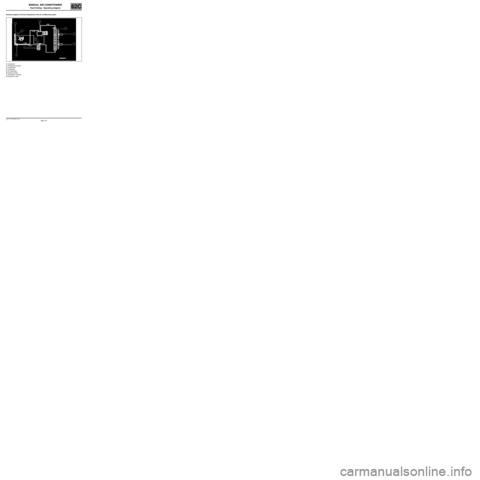
Summary diagram of all the components of the air conditioning system
1Evaporator
2Temperature sensor
3Compressor
4Condenser
5Fan assembly
6Pressure switch
7Dehydration canister
8Expansion valve
MR-413-X44-62C000$364_eng.mif
Page 19 of 63
62C-19
MR-413-X44-62C000$455_eng.mif
V1
MANUAL AIR CONDITIONING
Fault finding - Function62C
Vehicle
multiplex
network
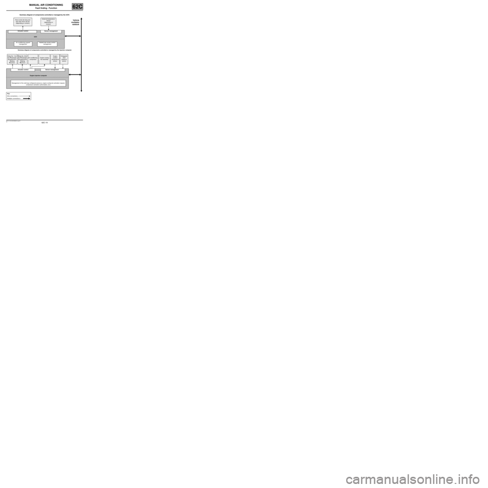
Summary diagram of components controlled or managed by the UCH:
Summary diagram of components controlled or managed by the injection computer Rear screen de-icing and
rear-view mirror de-icer
(depending on version)External temperature
sensor
(depending on
version)
Actuator control Sensor management
UCH
Air conditioning request
managementHeated rear screen control
management
Relay No. 1 for
the Passenger
Compartment
Heating
ResistorsRelay No. 2 for
the Passenger
Compartment
Heating
ResistorsAir conditioning
compressorEngine cooling
fan assemblyEngine
coolant
temperature
sensorRefrigerant
fluid
pressure
sensor
Actuator control Sensor management
Engine injection computer
Management of the cold loop (refrigerant pressure, engine cooling fan activation request,
compressor activation authorisation, etc.)
Key:
Wire connections =
Multiplex connections =
Page 48 of 63
62C-48
MR-413-X44-62C000$819_eng.mif
V1
MANUAL AIR CONDITIONING
Fault finding - Fault finding charts62C
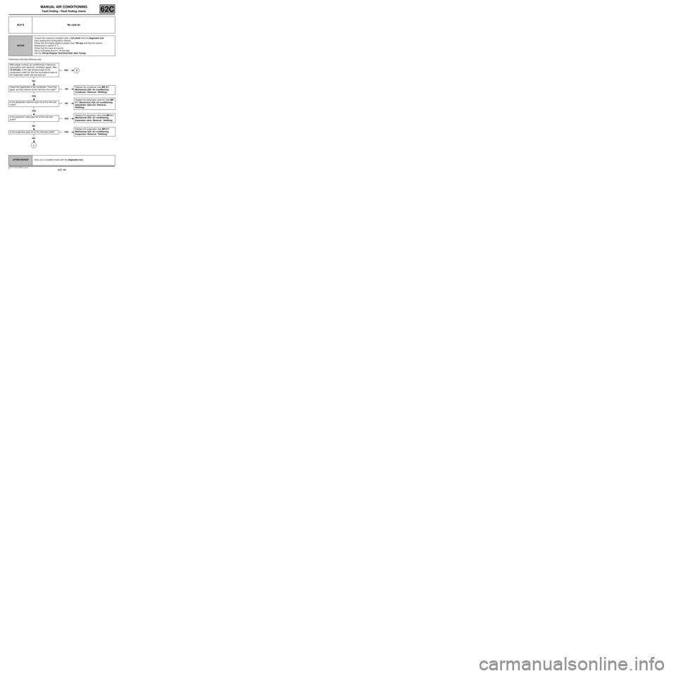
Preliminary cold loop efficiency test
ALP 8 No cold air
NOTESConsult this customer complaint after a full check with the diagnostic tool
(fault reading and configuration checks).
Check that the engine speed is greater than 750 rpm and that the exterior
temperature is above 3 ˚C.
Check that the fuses are sound.
Use a multimeter and a 21 W test light.
Use the Wiring Diagram Technical Note, New Twingo.
With engine running, air conditioning in maximum
cold position and maximum ventilation speed. After
10 minutes, is the high pressure pipe at the
compressor outlet hot, and the low pressure pipe at
the evaporator outlet cold and iced up?
NO
Check the cleanliness of the condenser. Touch the
pipes: are they warmer at the inlet than the outlet?
YES
Is the dehydrator reservoir pipe hot at the inlet and
outlet?
YES
Is the expansion valve pipe hot at the inlet and
outlet?
NO
Is the evaporator pipe hot at the inlet and outlet?
NO
1
YES2
NOReplace the condenser (see MR 411
Mechanical, 62A, Air conditioning,
Condenser: Removal - Refitting).
NOReplace the dehydrator reservoir (see MR
411 Mechanical, 62A, Air conditioning,
Dehydrator reservoir: Removal -
Refitting).
YESReplace the expansion valve (see MR 411
Mechanical, 62A, Air conditioning,
Expansion valve: Removal - Refitting).
YESReplace the evaporator (see MR 411
Mechanical, 62A, Air conditioning,
Evaporator: Removal - Refitting).
AFTER REPAIRCarry out a complete check with the diagnostic tool.
Page 56 of 63
62C-56
MR-413-X44-62C000$910_eng.mif
V1
62C
MANUAL AIR CONDITIONING
Fault finding - Fault finding charts
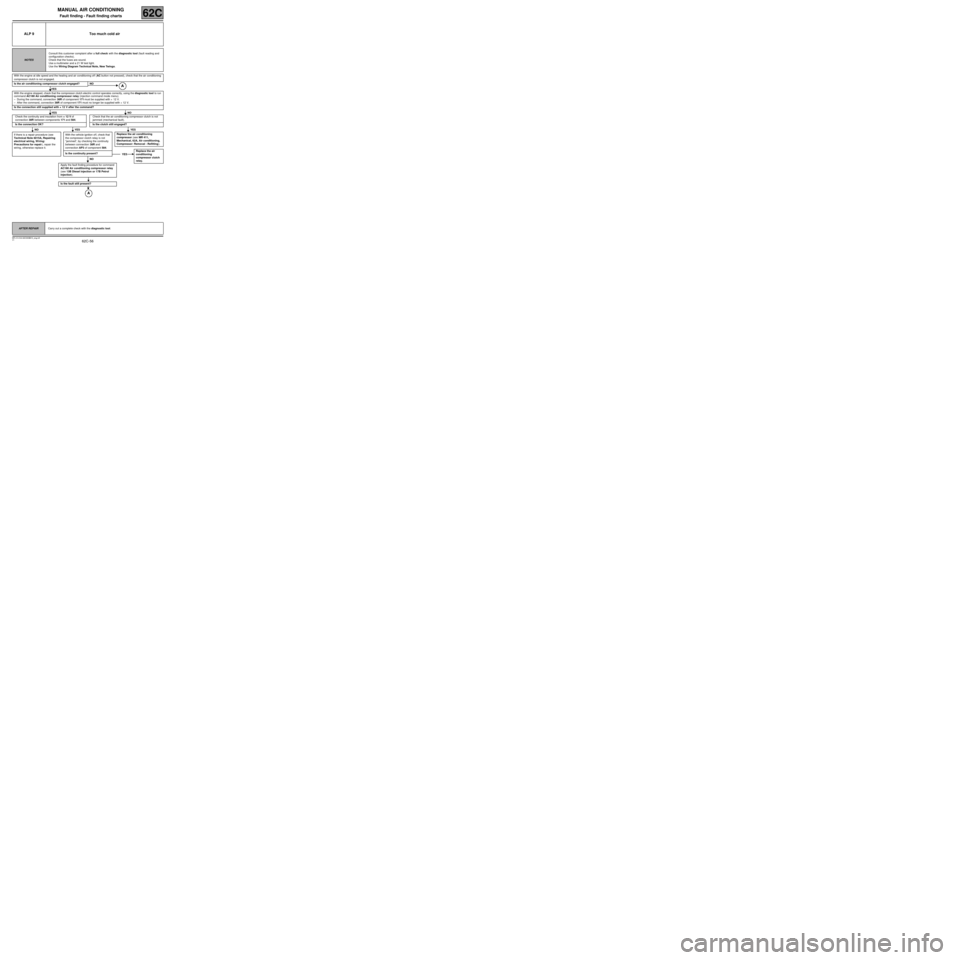
ALP 9 Too much cold air
NOTESConsult this customer complaint after a full check with the diagnostic tool (fault reading and
configuration checks).
Check that the fuses are sound.
Use a multimeter and a 21 W test light.
Use the Wiring Diagram Technical Note, New Twingo.
With the engine at idle speed and the heating and air conditioning off (AC button not pressed), check that the air conditioning
compressor clutch is not engaged.
Is the air conditioning compressor clutch engaged? NO
YES
With the engine stopped, check that the compressor clutch electric control operates correctly, using the diagnostic tool to run
command AC180 Air conditioning compressor relay (injection command mode menu).
–During the command, connection 38R of component 171 must be supplied with + 12 V.
–After the command, connection 38R of component 171 must no longer be supplied with + 12 V.
Is the connection still supplied with + 12 V after the command?
YES NO
Check the continuity and insulation from + 12 V of
connection 38R between components 171 and 584.Check that the air conditioning compressor clutch is not
jammed (mechanical fault).
Is the connection OK? Is the clutch still engaged?
NO YES YES
If there is a repair procedure (see
Technical Note 6015A, Repairing
electrical wiring, W iring:
Precautions for repair), repair the
wiring, otherwise replace it.With the vehicle ignition of f, check that
the compressor clutch relay is not
“jammed”, by checking the continuity
between connection 38R and
connection AP3 of component 584.
Is the continuity present?
NO
Apply the fault finding procedure for command
AC180 Air conditioning compressor relay
(see 13B Diesel injection or 17B Petrol
injection).
Is the fault still present?
Replace the air conditioning
compressor (see MR 411,
Mechanical, 62A, Air conditioning,
Compressor: Removal - Refitting).
YESReplace the air
conditioning
compressor clutch
relay.
AFTER REPAIRCarry out a complete check with the diagnostic tool.
MR-413-X44-62C000$910_eng.mif
Page 58 of 63
62C-58
MR-413-X44-62C000$910_eng.mif
V1
MANUAL AIR CONDITIONING
Fault finding - Fault finding charts62C
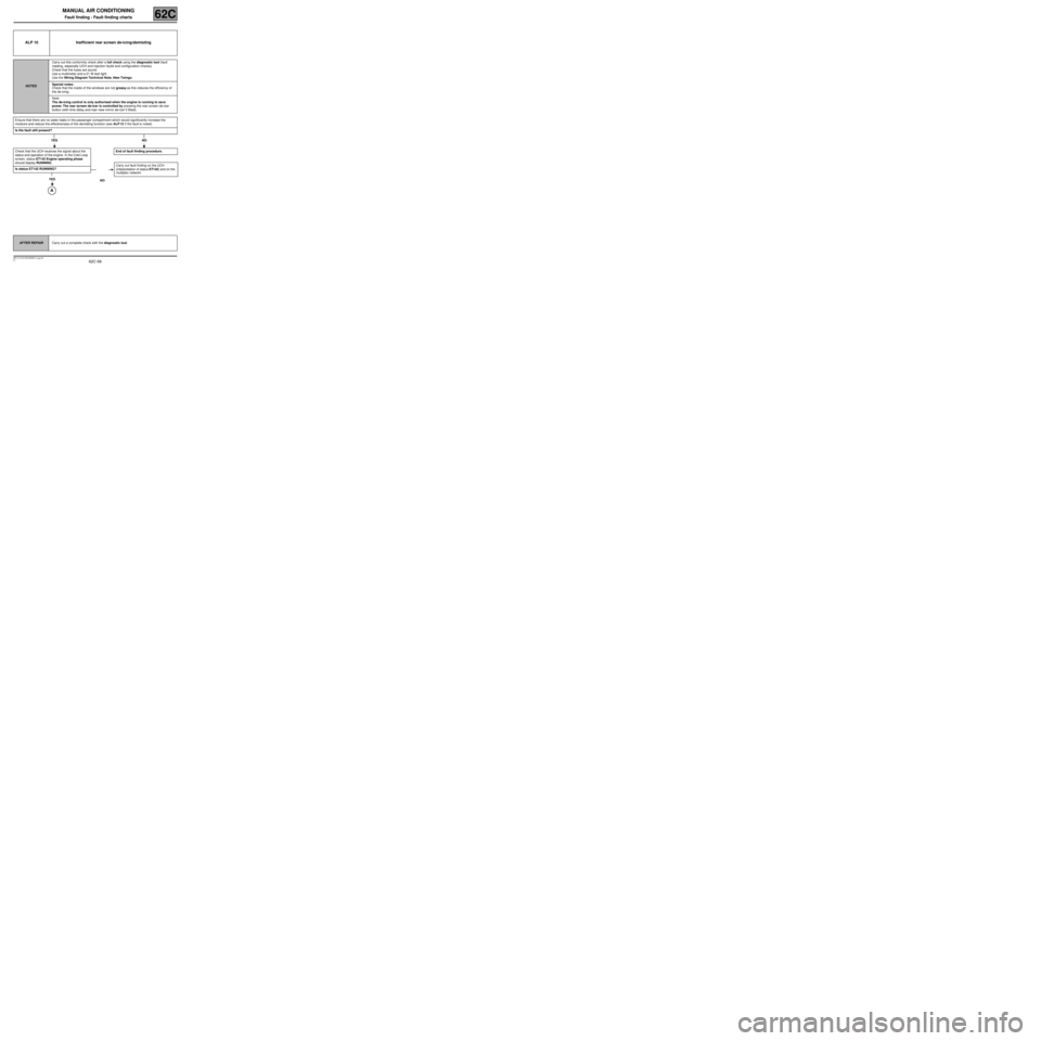
ALP 10 Inefficient rear screen de-icing/demisting
NOTESCarry out this conformity check after a full check using the diagnostic tool (fault
reading, especially UCH and injection faults and configuration checks).
Check that the fuses are sound.
Use a multimeter and a 21 W test light.
Use the Wiring Diagram Technical Note, New Twingo.
Special notes:
Check that the inside of the windows are not greasy as this reduces the efficiency of
the de-icing.
Note:
The de-icing control is only authorised when the engine is running to save
power. The rear screen de-icer is controlled by pressing the rear screen de-icer
button (with time delay and rear-view mirror de-icer if fitted).
Ensure that there are no water leaks in the passenger compartment which would significantly increase the
moisture and reduce the effectiveness of the demisting function (see ALP 12 if the fault is noted).
Is the fault still present?
YES NO
Check that the UCH receives the signal about the
status and operation of the engine. In the Cold Loop
screen, status ET142 Engine operating phase
should display RUNNING.
Is status ET142 RUNNING?
YES
End of fault finding procedure.
NOCarry out fault finding on the UCH
(interpretation of status ET142) and on the
multiplex network.
AFTER REPAIRCarry out a complete check with the diagnostic tool.