wiring RENAULT TWINGO RS 2009 2.G Mechanism And Accessories Workshop Manual
[x] Cancel search | Manufacturer: RENAULT, Model Year: 2009, Model line: TWINGO RS, Model: RENAULT TWINGO RS 2009 2.GPages: 95
Page 31 of 95
54A-1
WINDOWS
Windscreen: Removal - Refitting
54A
REMOVAL
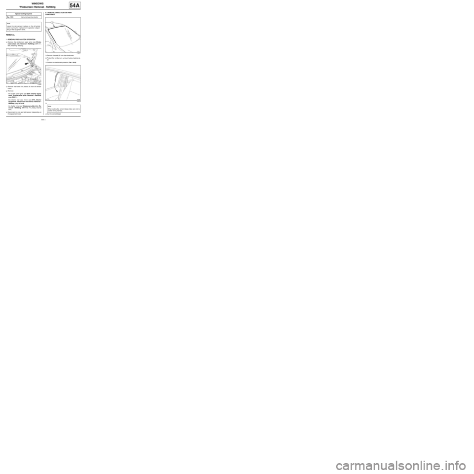
I - REMOVAL PREPARATION OPERATION
aRemove the windscreen wiper arms (see Winds-
creen wiper arm: Removal - Refitting) (MR 411,
85A, Washing - Wiping).
aRemove the lower trim pieces (1) from the winds-
creen.
aRemove:
-the scuttle panel grille (see 56A, Exterior equip-
ment, Scuttle panel grille: Removal - Refitting,
page 56A-1) ,
-the interior rear-view mirror (see 57A, Interior
equipment, Interior rear-view mirror: Removal -
Refitting, page 57A-14) ,
-the A-pillar trims (see Windscreen pillar trim: Re-
moval - Refitting) (MR 412, 71A, Body internal
trim).
aDisconnect the rain and light sensor (depending on
the equipment level).II - REMOVAL OPERATION FOR PART
CONCERNED
aRemove the seal (2) from the windscreen.
aProtect the windscreen surround using masking ta-
pe.
aPosition the dashboard protector (Car. 1818).
a
aCut the cement bead. Special tooling required
Car. 1818Instr ument panel protector
Note:
Leave the rain sensor in place on the old winds-
creen during the replacement operation (depen-
ding on the equipment level).
119268
119271
108156
Note:
When cutting the cement bead, take care not to
cut the wiring harness.
Page 41 of 95
55A-3
EXTERIOR PROTECTION
Front bumper: Stripping - Rebuilding
55A
STRIPPING
I - STRIPPING PREPARATION OPERATION
aRemove the front bumper (see 55A, Exterior pro-
tection, Front bumper: Removal - Refitting, page
55A-1) .
II - STRIPPING OPERATION FOR PART
CONCERNED
aRemove the front fog lights (depending on equip-
ment level) (see Front fog light: Removal - Refit-
ting) (MR 411, 80B, Headlights).
aNote the position of the electrical wiring (depending
on equipment level).
aRemove the electrical wiring (depending on equip-
ment level).
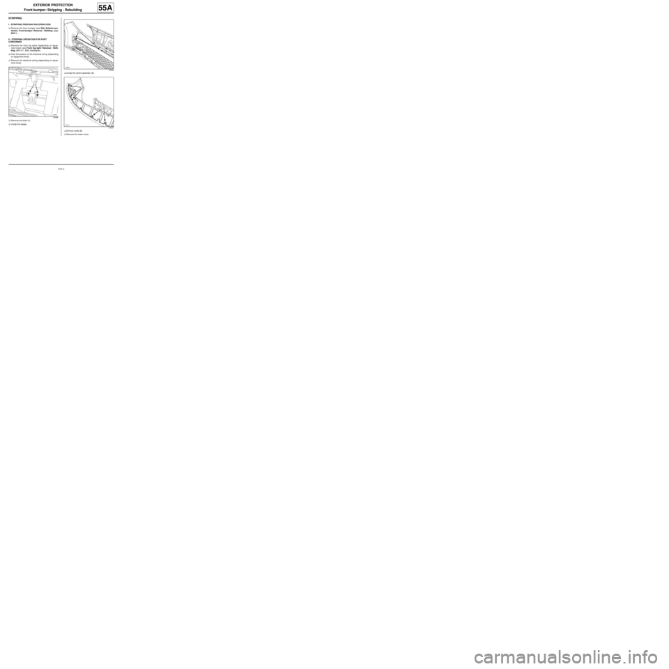
aRemove the bolts (1) .
aUnclip the badge.aUnclip the centre absorber (2) .
aDrill out rivets (3) .
aRemove the lower cover.
120886
120888
120887
Page 43 of 95

55A-5
EXTERIOR PROTECTION
Front bumper: Stripping - Rebuilding
55A
aInsert rivets into the lower cover at (3) .
aClip on:
-the central absorber (2) ,
-the badge.
aRefit:
-the bolts (1) ,
-the electrical wiring (depending on equipment le-
vel),
-the front fog lights (depending on the equipment le-
vel) (see Front fog light: Removal - Refitting)
(MR 411, 80B, Headlights).
II - FINAL OPERATION.
aRefit the front bumper (see 55A, Exterior protec-
tion, Front bumper: Removal - Refitting, page
55A-1) .
Page 51 of 95
55A-13
EXTERIOR PROTECTION
Rear bumper: Stripping - Rebuilding
55A
STRIPPING
I - STRIPPING PREPARATION OPERATION
aRemove the rear bumper (see 55A, Exterior pro-
tection, Rear bumper: Removal - Refitting, page
55A-10) .
II - STRIPPING OPERATION FOR PART
CONCERNED
aRemove the proximity radars (see Proximity radar:
Removal - Refitting) (87F, Parking distance con-
trol).
aRemove:
-the number plate lights (see Number plate light:
Removal - Refitting) (81A, Rear lighting),
-the electrical wiring.
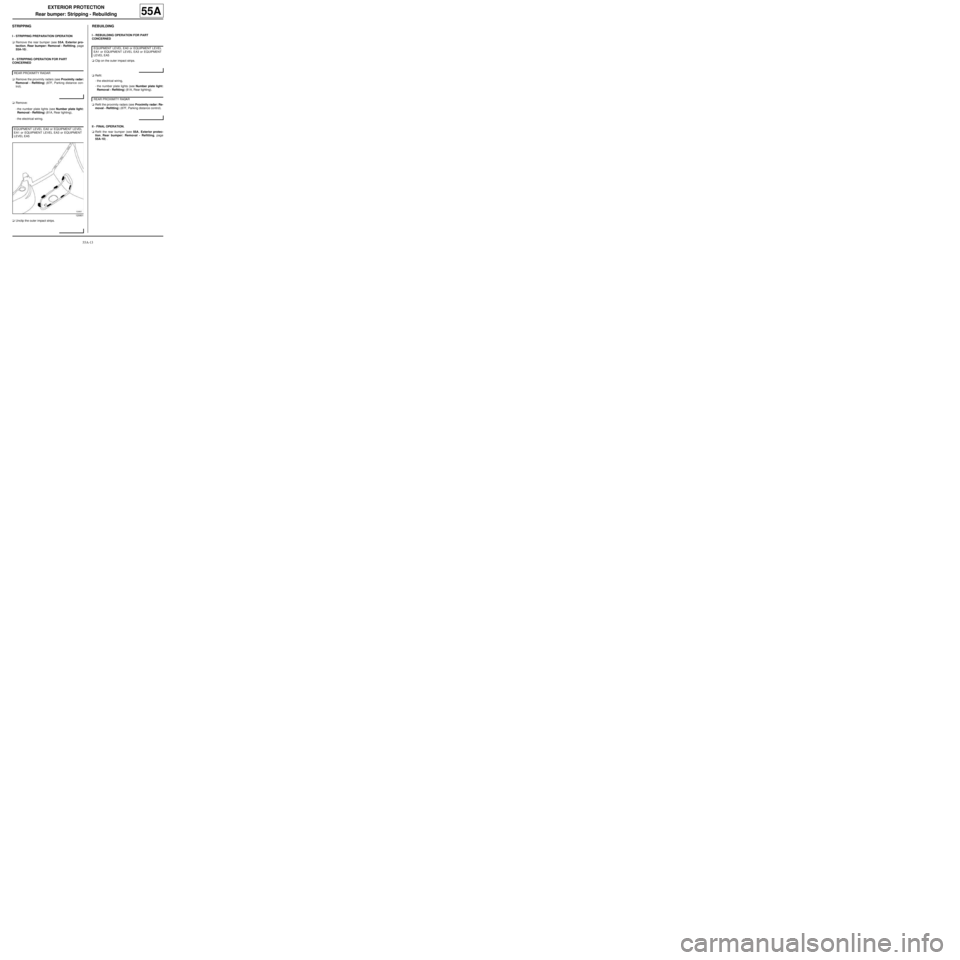
aUnclip the outer impact strips.
REBUILDING
I - REBUILDING OPERATION FOR PART
CONCERNED
aClip on the outer impact strips.
aRefit:
-the electrical wiring,
-the number plate lights (see Number plate light:
Removal - Refitting) (81A, Rear lighting).
aRefit the proximity radars (see Proximity radar: Re-
moval - Refitting) (87F, Parking distance control).
II - FINAL OPERATION.
aRefit the rear bumper (see 55A, Exterior protec-
tion, Rear bumper: Removal - Refitting, page
55A-10) . REAR PROXIMITY RADAR
EQUIPMENT LEVEL EA0 or EQUIPMENT LEVEL
EA1 or EQUIPMENT LEVEL EA3 or EQUIPMENT
LEVEL EA5
120801
EQUIPMENT LEVEL EA0 or EQUIPMENT LEVEL
EA1 or EQUIPMENT LEVEL EA3 or EQUIPMENT
LEVEL EA5
REAR PROXIMITY RADAR
Page 76 of 95
57A-3
INTERIOR EQUIPMENT
Dashboard: Removal - Refitting
57A
aPartially remove the dashboard (this operation re-
quires two people).
aDetach the various wiring from the dashboard.
aRemove the dashboard (this operation requires two
people).
aNote the route of the cabling.
REFITTING
I - REFITTING PREPARATION OPERATION
aEnsure that the wiring is in good condition.
II - REFITTING OPERATION FOR PART
CONCERNED
aPartially refit the dashboard (this operation requires
two people).
aRefit:
-the various cable harnesses,
-the dashboard (this operation requires two people).
III - FINAL OPERATION.
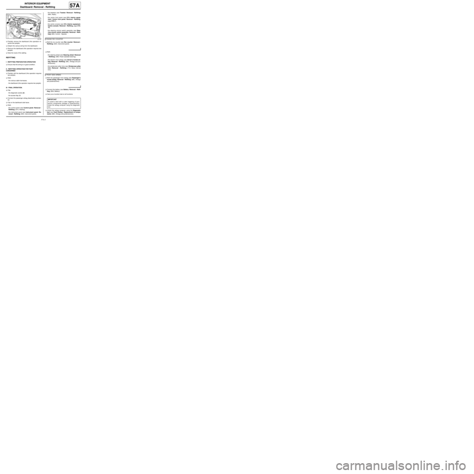
aClip:
-the diagnostic socket (2) ,
-the access flap (1) .
aConnect the passenger airbag deactivation connec-
tor.
aClip on the dashboard side faces.
aRefit:
-the control panel (see Control panel: Removal -
Refitting) (61A, Heating),
-the instrument panel (see Instrument panel: Re-
moval - Refitting) (83A, Instrument panel),-the tweeters (see Tweeter: Removal - Refitting)
(86A, Radio),
-the centre front panel (see 57A, Interior equip-
ment, Centre front panel: Removal - Refitting,
page 57A-7) ,
-the centre console (see 57A, Interior equipment,
Centre console: Removal - Refitting, page 57A-
12) ,
-the steering column switch assembly (see Stee-
ring column switch assembly: Removal - Refit-
ting) (84A, Control - Signals).
aRefit the rev counter (see Rev counter: Removal -
Refitting) (83A, Instrument panel).
aRefit:
-the steering wheel (see Steering wheel: Removal
- Refitting) (36B, Power-assisted steering),
-the driver's front airbag (see Driver's frontal air-
bag: Removal - Refitting) (88C, Airbags and pre-
tensioners),
-the windscreen pillar trims (see Windscreen pillar
trim: Removal - Refitting) (71A, Body internal
trim).
aRefit the passenger front airbag (see Passenger's
frontal airbag: Removal - Refitting) (88C, Airbags
and pretensioners).
aConnect the battery (see Battery: Removal - Refit-
ting) (80A, Battery).
aCarry out a function test on all functions.
aUnlock the airbag computer using the Diagnostic
tool (see Fault finding - Replacement of compo-
nents) (88C, Airbags and pretensioners).
121157ENGINE REV COUNTER
FRONT SIDE AIRBAG
IMPORTANT
To avoid a fault with or even triggering of pyro-
technic components (airbags or pretensioners),
check the airbag computer using the diagnostic
tool.
Page 77 of 95
57A-4
INTERIOR EQUIPMENT
Dashboard: Conversion
57A
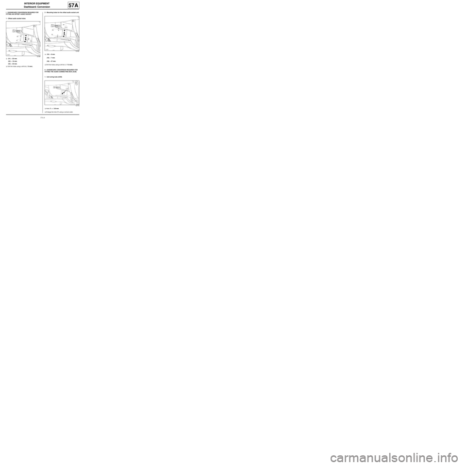
I - DASHBOARD CONVERSION REQUIRED FOR
FITTING AN OFFSET AUDIO SOCKET
1 - Offset audio socket holes
a (X1) = 22 mm.
(X2) = 16 mm.
(X3) = 23 mm.
aDrill the holes using a drill bit (∅ 9 mm).2 - Mounting holes for the offset audio socket unit
a (X4) = 8 mm.
(X5) = 7 mm.
(X6) = 27 mm.
aDrill the holes using a drill bit (∅ 7.5 mm).
II - DASHBOARD CONVERSION REQUIRED FOR
FITTING THE AUDIO CONNECTING BOX (ACB)
1 - Unit wiring hole (ACB)
aHole (7) =∅ 20 mm.
aEnlarge the hole (7) using a conical cutter.
121381
121381
127770