sensor RENAULT TWINGO RS 2009 2.G Transmission Owner's Guide
[x] Cancel search | Manufacturer: RENAULT, Model Year: 2009, Model line: TWINGO RS, Model: RENAULT TWINGO RS 2009 2.GPages: 135
Page 113 of 135
29A-5
DRIVESHAFTS
Front left-hand driveshaft: Removal - Refitting
JH3 or JR5
29A
REMOVAL
I - REMOVAL PREPARATION OPERATION
aPosition the vehicle on a two-post lift (see Vehicle:
Towing and lifting) (02A, Lifting equipment).
aRemove:
-the engine undertray.
-the front left-hand wheel (see Wheel: Removal -
Refitting) (35A, Wheels and tyres).
aDrain the gearbox (see 21A, Manual gearbox,
Manual gearbox oils: Draining - Filling, page
21A-2) .II - OPERATION FOR REMOVAL OF PART
CONCERNED
aUnclip:
-the wheel speed sensor wiring (1) ,
-the brake hose (2) .
aRemove:
-the hub nut (3) by immobilising the hub using the
tool (Rou. 604-01),
-the track rod end nut (4) ,
-the shock absorber base bolts (5) . Special tooling required
Rou. 604-01Hub locking tool.
Emb. 880Pin extractor tool.
Tav. 1813Extraction claw for clip
secured type driveshafts
Tightening torquesm
shock absorber base
bolts105 N.m
track rod end nut37 N.m
hub nut280 N.m
WARNING
In order to prevent irreversible damage to the front
hub bear ing:
-Do not loosen or tighten the driveshaft nut when
the wheels are on the ground.
-Do not place the vehicle with its wheels on the
ground when the driveshaft has been loosened or
removed.
132032
Page 115 of 135
29A-7
DRIVESHAFTS
Front left-hand driveshaft: Removal - Refitting
JH3 or JR5
29A
REFITTING
I - REFITTING PREPARATION OPERATION
aAlways replace the differential output seal (see 21A,
Manual gearbox, Differential output seal: Re-
moval - Refitting, page 21A-38) .
II - REFITTING OPERATION FOR PART
CONCERNED
aFit the front left-hand driveshaft into the gearbox as
horizontally as possible.
aFit the front left-hand driveshaft into the stub axle
carrier.
aRefit the bolts to the shock absorber base.
aTorque tighten the shock absorber base bolts
(105 N.m).
aPosition the track rod.
aTorque tighten the track rod end nut (37 N.m).
aRefit the hub nut.
aTorque tighten the hub nut (280 N.m) using the tool
(Rou. 604-01).
aRefit the left-hand tie-rod.
aRefit the lower nut for the left-hand anti-roll bar tie-
rod.
aClip:
-the brake hose,
-the wheel speed sensor wiring.
III - FINAL OPERATION
aTop up the gearbox (see 21A, Manual gearbox,
Manual gearbox oils: Draining - Filling, page
21A-2) .
aRefit:
-the front left-hand wheel (see Wheel: Removal -
Refitting) (35A, Wheels and tyres),
-the engine undertray.Note:
The driveshaft must fit freely into the stub-axle
carrier until it protrudes enough for the hub nut to
be fitted.
Page 116 of 135
29A-8
DRIVESHAFTS
Front right-hand driveshaft: Removal - Refitting
JB1 or JH1
29A
REMOVAL
I - REMOVAL PREPARATION OPERATION
aPosition the vehicle on a two-post lift (see Vehicle:
Towing and lifting) (02A, Lifting equipment).
aRemove:
-the engine undertray bolts,
-the engine undertray,
-the front right-hand wheel (see Wheel: Removal -
Refitting) (35A, Wheels and tyres).II - OPERATION FOR REMOVAL OF PART
CONCERNED
aDetach the wiring from the wheel speed sensor (1) .
aRemove:
-the hub nut (2) by immobilising the hub using the
tool (Rou. 604-01),
-the track rod end nut (3) ,
-the track rod end from the stub axle carrier using
the (Tav. 476),
-the shock absorber base bolts (4) . Special tooling required
Rou. 604-01Hub locking tool.
Tav. 476Ball joint extractor.
Tightening torquesm
shock absorber base
bolts105 N.m
track rod end nut37 Nm
hub nut280 N.m
WARNING
In order to prevent irreversible damage to the front
hub bear ing:
-Do not loosen or tighten the driveshaft nut when
the wheels are on the ground.
-Do not place the vehicle with its wheels on the
ground when the driveshaft has been loosened or
removed.
130490
Page 117 of 135
29A-9
DRIVESHAFTS
Front right-hand driveshaft: Removal - Refitting
JB1 or JH1
29A
aPush the front right-hand driveshaft back from the
stub axle carrier by pivoting the stub axle carrier.
aRemove the front right-hand driveshaft.
REFITTING
I - REFITTING OPERATION FOR PART
CONCERNED
aFit the front right-hand driveshaft to the gearbox sun-
wheel.
aFit the front right-hand driveshaft into the stub axle
carrier.
aRefit the bolts to the shock absorber base.
aTorque tighten the shock absorber base bolts
(105 N.m).
aPosition the track rod.
aTorque tighten the track rod end nut (37 Nm).
aRefit the hub nut.
aTorque tighten the hub nut (280 N.m) using the tool
(Rou. 604-01).
aClip on the wheel speed sensor wiring harness.II - FINAL OPERATION.
aRefit:
-the front right-hand wheel (see Wheel: Removal -
Refitting) (35A, Wheels and tyres),
-the engine undertray.
130491
Note:
The driveshaft must fit freely into the stub-axle
carrier until it protrudes enough for the hub nut to
be fitted.
Page 118 of 135
29A-10
DRIVESHAFTS
Front right-hand driveshaft: Removal - Refitting
JH3 or JR5
29A
REMOVAL
I - REMOVAL PREPARATION OPERATION
aPosition the vehicle on a two-post lift (see Vehicle:
Towing and lifting) (02A, Lifting equipment).
aRemove:
-the engine undertray,
-the front right-hand wheel (see Wheel: Removal -
Refitting) (35A, Wheels and tyres).
aDrain the gearbox (see 21A, Manual gearbox,
Manual gearbox oils: Draining - Filling, page
21A-2) .II - OPERATION FOR REMOVAL OF PART
CONCERNED
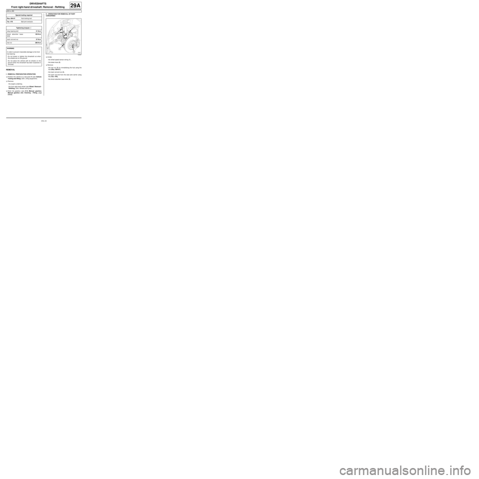
aUnclip:
-the wheel speed sensor wiring (1) ,
-the brake hose (2) .
aRemove:
-the hub nut (3) by immobilising the hub using the
tool (Rou. 604-01),
-the track rod end nut (4) ,
-the track rod end from the stub axle carrier using
the (Tav. 476),
-the shock absorber base bolts (5) . Special tooling required
Rou. 604-01Hub locking tool.
Tav. 476Ball joint extractor.
Tightening torquesm
relay bearing bolt21 N.m
shock absorber base
bolts105 N.m
track rod end nut37 N.m
hub nut280 N.m
WARNING
In order to prevent irreversible damage to the front
hub bear ing:
-Do not loosen or tighten the driveshaft nut when
the wheels are on the ground.
-Do not place the vehicle with its wheels on the
ground when the driveshaft has been loosened or
removed.
132027
Page 119 of 135
29A-11
DRIVESHAFTS
Front right-hand driveshaft: Removal - Refitting
JH3 or JR5
29A
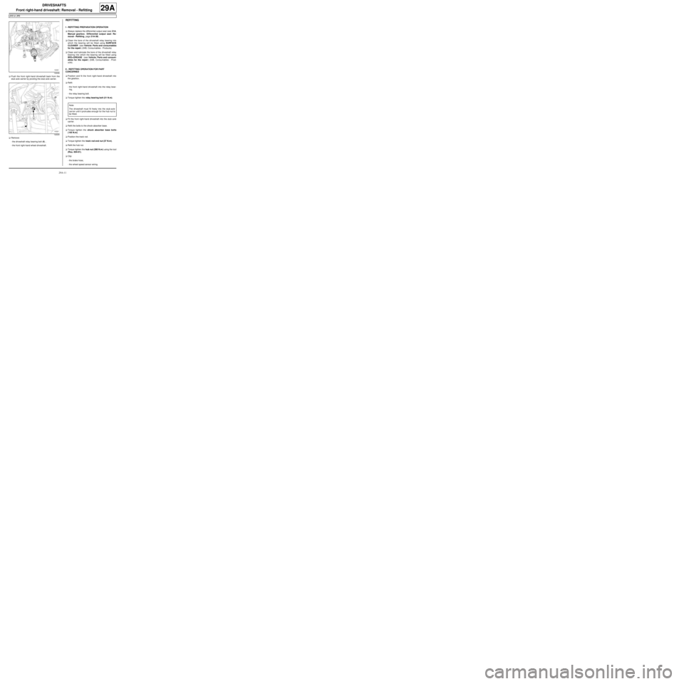
aPush the front right-hand driveshaft back from the
stub axle carrier by pivoting the stub axle carrier.
aRemove:
-the driveshaft relay bearing bolt (6) ,
-the front right-hand wheel driveshaft.
REFITTING
I - REFITTING PREPARATION OPERATION
aAlways replace the differential output seal (see 21A,
Manual gearbox, Differential output seal: Re-
moval - Refitting, page 21A-38) .
aClean the bore of the driveshaft relay bearing into
which the bearing will be fitted using SURFACE
CLEANER (see Vehicle: Parts and consumables
for the repair) (04B, Consumables - Products).
aClean and lubricate the bore of the driveshaft relay
bearing into which the bearing will be fitted using
BR2+GREASE (see Vehicle: Parts and consum-
ables for the repair) (04B, Consumables - Prod-
ucts).
II - REFITTING OPERATION FOR PART
CONCERNED
aPosition and fit the front right-hand driveshaft into
the gearbox.
aRefit:
-the front right-hand driveshaft into the relay bear-
ing,
-the relay bearing bolt.
aTorque tighten the relay bearing bolt (21 N.m).
aFit the front right-hand driveshaft into the stub axle
carrier.
aRefit the bolts to the shock absorber base.
aTorque tighten the shock absorber base bolts
(105 N.m).
aPosition the track rod.
aTorque tighten the track rod end nut (37 N.m).
aRefit the hub nut.
aTorque tighten the hub nut (280 N.m ) using the tool
(Rou. 604-01).
aClip:
-the brake hose,
-the wheel speed sensor wiring.
132026
132025
Note:
The driveshaft must fit freely into the stub-axle
carr ier until it protrudes enough for the hub nut to
be fitted.