stop start SATURN AURA 2009 Owner's Manual
[x] Cancel search | Manufacturer: SATURN, Model Year: 2009, Model line: AURA, Model: SATURN AURA 2009Pages: 408, PDF Size: 2.61 MB
Page 265 of 408

While refueling, hang the tethered fuel cap from the
hook on the fuel door.
{CAUTION:
Fuel can spray out on you if you open the fuel cap
too quickly. If you spill fuel and then something
ignites it, you could be badly burned. This spray
can happen if the tank is nearly full, and is more
likely in hot weather. Open the fuel cap slowly and
wait for any hiss noise to stop. Then unscrew the
cap all the way.
Be careful not to spill fuel. Do not top off or over�ll the
tank and wait a few seconds after you have �nished
pumping the fuel before removing the nozzle. Clean fuel
from painted surfaces as soon as possible. SeeWashing
Your Vehicle on page 5-85.
When replacing the fuel cap, turn it to the clockwise
until it clicks. Make sure the cap is fully installed.
The diagnostic system can determine if the fuel cap
has been left off or improperly installed. This would allow
fuel to evaporate into the atmosphere. SeeMalfunction
Indicator Lamp on page 3-37.If the vehicle has a Driver Information Center (DIC),
the CHECK GAS CAP message displays if the fuel cap
is not properly installed.
{CAUTION:
If a �re starts while you are refueling, do not
remove the nozzle. Shut off the �ow of fuel by
shutting off the pump or by notifying the station
attendant. Leave the area immediately.
Notice:If you need a new fuel cap, be sure to get
the right type. Your dealer/ retailer can get one
for you. If you get the wrong type, it might not �t
properly. This can cause the malfunction indicator
lamp to light and can damage the fuel tank and
emissions system. SeeMalfunction Indicator Lamp
on page 3-37.
5-9
ProCarManuals.com
Page 282 of 408

How to Add Coolant to the Radiator
{CAUTION:
An electric engine cooling fan under the hood can
start up even when the engine is not running and
can cause injury. Keep hands, clothing, and tools
away from any underhood electric fan.
{CAUTION:
Steam and scalding liquids from a hot cooling
system can blow out and burn you badly. They are
under pressure, and if you turn the surge tank
pressure cap — even a little — they can come
out at high speed. Never turn the cap when the
cooling system, including the surge tank pressure
cap, is hot. Wait for the cooling system and surge
tank pressure cap to cool if you ever have to turn
the pressure cap.If coolant is needed, add the proper mixture directly to
the radiator, but be sure the cooling system is cool
before this is done.
1. Remove the coolant surge tank pressure cap when
the cooling system, including the coolant surge tank
pressure cap and upper radiator hose, is no longer
hot. Turn the pressure cap slowly counterclockwise
about two or two and one-half turns.
If you hear a hiss, wait for that to stop. This will
allow any pressure still left to be vented out the
discharge hose.
2. Then keep turning the
pressure cap slowly,
and remove it.
5-26
ProCarManuals.com
Page 310 of 408

Tire Pressure Monitor System
The Tire Pressure Monitor System (TPMS) uses radio
and sensor technology to check tire pressure levels.
The TPMS sensors monitor the air pressure in
your vehicle’s tires and transmit tire pressure readings
to a receiver located in the vehicle.
Each tire, including the spare (if provided), should be
checked monthly when cold and in�ated to the in�ation
pressure recommended by the vehicle manufacturer
on the vehicle placard or tire in�ation pressure label.
(If your vehicle has tires of a different size than the
size indicated on the vehicle placard or tire in�ation
pressure label, you should determine the proper
tire in�ation pressure for those tires.)
As an added safety feature, your vehicle has been
equipped with a tire pressure monitoring system (TPMS)
that illuminates a low tire pressure telltale when one
or more of your tires is signi�cantly under-in�ated.
Accordingly, when the low tire pressure telltale
illuminates, you should stop and check your tires as
soon as possible, and in�ate them to the proper pressure.
Driving on a signi�cantly under-in�ated tire causes the
tire to overheat and can lead to tire failure. Under-in�ation
also reduces fuel efficiency and tire tread life, and may
affect the vehicle’s handling and stopping ability.Please note that the TPMS is not a substitute for proper
tire maintenance, and it is the driver’s responsibility to
maintain correct tire pressure, even if under-in�ation
has not reached the level to trigger illumination of
the TPMS low tire pressure telltale.
Your vehicle has also been equipped with a TPMS
malfunction indicator to indicate when the system is
not operating properly. The TPMS malfunction indicator
is combined with the low tire pressure telltale. When the
system detects a malfunction, the telltale will �ash for
approximately one minute and then remain continuously
illuminated. This sequence will continue upon
subsequent vehicle start-ups as long as the malfunction
exists.
When the malfunction indicator is illuminated, the
system may not be able to detect or signal low tire
pressure as intended. TPMS malfunctions may occur
for a variety of reasons, including the installation of
replacement or alternate tires or wheels on the vehicle
that prevent the TPMS from functioning properly. Always
check the TPMS malfunction telltale after replacing one
or more tires or wheels on your vehicle to ensure that
the replacement or alternate tires and wheels allow the
TPMS to continue to function properly.
SeeTire Pressure Monitor Operation on page 5-55for
additional information.
5-54
ProCarManuals.com
Page 313 of 408

One or more TPMS sensors are missing or
damaged. The DIC message and the TPMS
malfunction light should go off when the TPMS
sensors are installed and the sensor matching
process is performed successfully. See your
dealer/retailer for service.
Replacement tires or wheels do not match your
vehicle’s original equipment tires or wheels. Tires
and wheels other than those recommended for your
vehicle could prevent the TPMS from functioning
properly. SeeBuying New Tires on page 5-61.
Operating electronic devices or being near facilities
using radio wave frequencies similar to the TPMS
could cause the TPMS sensors to malfunction.
If the TPMS is not functioning it cannot detect or
signal a low tire condition. See your dealer/retailer for
service if the TPMS malfunction light and DIC message
comes on and stays on.
TPMS Sensor Matching Process
Each TPMS sensor has a unique identi�cation code.
Any time you replace one or more of the TPMS sensors
or rotate the vehicle’s tires, the identi�cation codes need
to be matched to the new tire/wheel location. The sensors
are matched, to the tire/wheel locations, in the following
order: driver side front tire, passenger side front tire,
passenger side rear tire, and driver side rear tire using
a TPMS diagnostic tool. See your dealer/retailer for
service.
The TPMS sensors can also be matched to each
tire/wheel position by increasing or decreasing the tire’s
air pressure. When increasing the tire’s pressure, do not
exceed the maximum in�ation pressure indicated on the
tire’s sidewall. To decrease the tire’s air-pressure use the
pointed end of the valve cap, a pencil-style air pressure
gage, or a key.
You have two minutes to match each tire and wheel
position. If it takes longer than two minutes to match
any tire and wheel position, the matching process stops
and you need to start over.
5-57
ProCarManuals.com
Page 314 of 408

The TPMS matching process is outlined below:
1. Set the parking brake.
2. Turn the ignition switch to ON/RUN with the
engine off.
3. Press and hold the Remote Keyless Entry (RKE)
transmitter’s LOCK and UNLOCK buttons, at the
same time, for about �ve seconds to start the TPMS
learn mode. The horn sounds twice indicating the
TPMS receiver is ready and in learn mode.
4. Start with the driver side front tire. The driver side
front turn signal also comes on to indicate that
corner’s sensor is ready to be learned.
5. Remove the valve cap from the tire’s valve
stem. Activate the TPMS sensor by increasing
or decreasing the tire’s air pressure for about
eight seconds. The horn chirp, can take up to
30 seconds to sound. It chirps one time and then
all the turn signals �ash one time to con�rm the
sensor identi�cation code has been matched to
the tire/wheel position.
6. The passenger side front turn signal comes on to
indicate that corner sensor is ready to be learned.
Proceed to the passenger side front tire and
repeat the procedure in Step 5.7. The passenger side rear turn signal comes on to
indicate that corner sensor is ready to be learned.
Proceed to the passenger side rear tire and
repeat the procedure in Step 5.
8. The driver side rear turn signal comes on to
indicate that corner sensor is ready to be learned.
Proceed to the driver side rear tire, and repeat
the procedure in Step 5.
9. After hearing the single horn chirp for the driver
side rear tire, two additional horn chirps sound
to indicate the tire learning process is done.
Turn the ignition switch to LOCK/OFF.
If no tires are learned after entering the TPMS learn
mode, or if communication with the receiver stops, or
if the time limit has expired, turn the ignition switch to
LOCK/OFF and start over beginning with Step 2.
10. Set all four tires to the recommended air pressure
level as indicated on the Tire and Loading
Information label.
11. Put the valve caps back on the valve stems.
5-58
ProCarManuals.com
Page 352 of 408

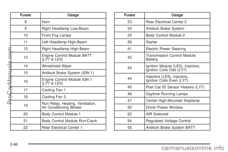
Fuses Usage
8 Horn
9 Right Headlamp Low-Beam
10 Front Fog Lamps
11 Left Headlamp High-Beam
12 Right Headlamp High-Beam
13Engine Control Module BATT
(LY7 & LE5)
14 Windshield Wiper
15 Antilock Brake System (IGN 1)
16Engine Control Module IGN 1
(LY7 & LE5)
17 Cooling Fan 1
18 Cooling Fan 2
19Run Relay, Heating, Ventilation,
Air Conditioning Blower
20 Body Control Module 1
21 Body Control Module Run/Crank
22 Rear Electrical Center 1Fuses Usage
23 Rear Electrical Center 2
24 Antilock Brake System
25 Body Control Module 2
26 Starter
41 Electric Power Steering
42Transmission Control Module
Battery
43Ignition Module (LE5); Injectors,
Ignition Coils Odd (LY7)
44Injectors (LE5); Injectors,
Ignition Coils Even (LY7)
45 Post Cat 02 Sensor Heaters (LY7)
46 Daytime Running Lamps
47 Center High-Mounted Stoplamp
50 Driver Power Window
52 AIR Solenoid
54 Regulated Voltage Control
55 Antilock Brake System BATT
5-96
ProCarManuals.com
Page 353 of 408

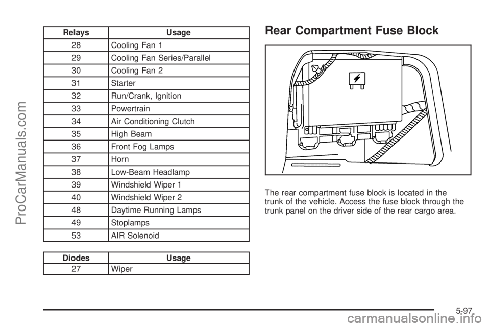
Relays Usage
28 Cooling Fan 1
29 Cooling Fan Series/Parallel
30 Cooling Fan 2
31 Starter
32 Run/Crank, Ignition
33 Powertrain
34 Air Conditioning Clutch
35 High Beam
36 Front Fog Lamps
37 Horn
38 Low-Beam Headlamp
39 Windshield Wiper 1
40 Windshield Wiper 2
48 Daytime Running Lamps
49 Stoplamps
53 AIR Solenoid
Diodes Usage
27 Wiper
Rear Compartment Fuse Block
The rear compartment fuse block is located in the
trunk of the vehicle. Access the fuse block through the
trunk panel on the driver side of the rear cargo area.
5-97
ProCarManuals.com