climate control SATURN AURA 2010 User Guide
[x] Cancel search | Manufacturer: SATURN, Model Year: 2010, Model line: AURA, Model: SATURN AURA 2010Pages: 428, PDF Size: 2.78 MB
Page 153 of 428
Instrument Panel Overview...............................4-3
Hazard Warning Flashers................................4-3
Horn .............................................................4-3
Tilt and Telescopic Steering Wheel...................4-3
Turn Signal/Multifunction Lever.........................4-4
Turn and Lane-Change Signals........................4-4
Headlamp High/Low-Beam Changer..................4-5
Flash-to-Pass.................................................4-5
Windshield Wipers..........................................4-5
Windshield Washer.........................................4-6
Cruise Control................................................4-7
Headlamps..................................................4-10
Headlamps on Reminder................................4-10
Headlamps Off in Park..................................4-10
Delayed Headlamps......................................4-11
Daytime Running Lamps (DRL).......................4-11
Automatic Headlamp System..........................4-11
Fog Lamps ..................................................4-12
Instrument Panel Brightness...........................4-13
Dome Lamps ...............................................4-13
Entry/Exit Lighting.........................................4-13
Parade Dimming...........................................4-13
Reading Lamps............................................4-13Electric Power Management...........................4-14
Battery Run-Down Protection..........................4-14
Accessory Power Outlet(s).............................4-15
Climate Controls............................................4-16
Climate Control System.................................4-16
Automatic Climate Control System...................4-19
Outlet Adjustment.........................................4-23
Warning Lights, Gages, and Indicators............4-24
Instrument Panel Cluster................................4-25
Speedometer and Odometer...........................4-26
Trip Odometer..............................................4-26
Tachometer................................................
.4-26
Safety Belt Reminders...................................4-26
Airbag Readiness Light..................................4-28
Passenger Airbag Status Indicator...................4-29
Charging System Light..................................4-30
Brake System Warning Light..........................4-30
Antilock Brake System (ABS) Warning Light.....4-31
Electronic Stability Control (ESC)/Traction
Control System (TCS) Indicator/Warning
Light........................................................4-32
Engine Coolant Temperature Warning Light......4-33
Engine Coolant Temperature Gage..................4-33
Section 4 Instrument Panel
4-1
ProCarManuals.com
Page 166 of 428
Electric Power Management
The vehicle has Electric Power Management (EPM) that
estimates the battery’s temperature and state of
charge. It then adjusts the voltage for best performance
and extended life of the battery.
When the battery’s state of charge is low, the voltage is
raised slightly to quickly bring the charge back up.
When the state of charge is high, the voltage is lowered
slightly to prevent overcharging. If the vehicle has a
voltmeter gage or a voltage display on the Driver
Information Center (DIC), you may see the voltage move
up or down. This is normal. If there is a problem, an
alert will be displayed.
The battery can be discharged at idle if the electrical
loads are very high. This is true for all vehicles. This is
because the generator (alternator) may not be
spinning fast enough at idle to produce all the power
that is needed for very high electrical loads.
A high electrical load occurs when several of the
following are on, such as: headlamps, high beams, fog
lamps, rear window defogger, climate control fan at
high speed, heated seats, engine cooling fans, trailer
loads, and loads plugged into accessory power outlets.
EPM works to prevent excessive discharge of the
battery. It does this by balancing the generator’s output
and the vehicle’s electrical needs. It can increaseengine idle speed to generate more power, whenever
needed. It can temporarily reduce the power demands of
some accessories.
Normally, these actions occur in steps or levels, without
being noticeable. In rare cases at the highest levels
of corrective action, this action may be noticeable to the
driver. If so, a Driver Information Center (DIC)
message might be displayed, such as BATTERY
SAVER ACTIVE, BATTERY VOLTAGE LOW, or LOW
BATTERY. If this message is displayed, it is
recommended that the driver reduce the electrical loads
as much as possible. SeeDIC Warnings and Messages
on page 4-42.
Battery Run-Down Protection
The battery run-down feature is designed to protect the
vehicle’s battery.
When any interior lamp (trunk, reading lamps, or dome
lamp) is left on when the ignition is turned off, the
battery run-down protection system automatically shuts
the lamp off after 20 minutes. This prevents draining
of the battery.
To reactivate the interior lamps, do one of the following:
•Open any door.
•Press any Remote Keyless Entry (RKE) transmitter
button.
4-14
ProCarManuals.com
Page 167 of 428

•Press the power door lock switch.
•Press the remote trunk release.
•Turn the lamp that was left on to off and then
to on again.
Accessory Power Outlet(s)
Accessory power outlets can be used to connect
auxiliary electrical equipment, such as a cellular
telephone.
There are two accessory power outlets. One accessory
power outlet is inside the center storage console and
the other is located on the center storage console below
the climate controls.
To use an outlet, lift the protective cap. When not in
use, always cover the outlet with the protective cap.
The accessory power outlet is operational at all times.
Notice:Leaving electrical equipment plugged in for
an extended period of time while the vehicle is off
will drain the battery. Power is always supplied
to the outlets. Always unplug electrical equipment
when not in use and do not plug in equipment
that exceeds the maximum 20 ampere rating.Certain electrical accessories may not be compatible
with the accessory power outlet and could result
in blown vehicle or adapter fuses. If you experience a
problem, see your retailer for additional information
on the accessory power outlet.
Notice:Adding any electrical equipment to your
vehicle can damage it or keep other components
from working as they should. The repairs would not
be covered by your warranty. Do not use equipment
exceeding maximum amperage rating of 20 amperes.
Check with your dealer/retailer before adding
electrical equipment.
When adding electrical equipment, be sure to follow the
proper installation instructions included with the
equipment.
Notice:Improper use of the power outlet can cause
damage not covered by the vehicle warranty. Do
not hang any type of accessory or accessory
bracket from the plug because the power outlets are
designed for accessory power plugs only.
4-15
ProCarManuals.com
Page 168 of 428
Climate Controls
Climate Control System
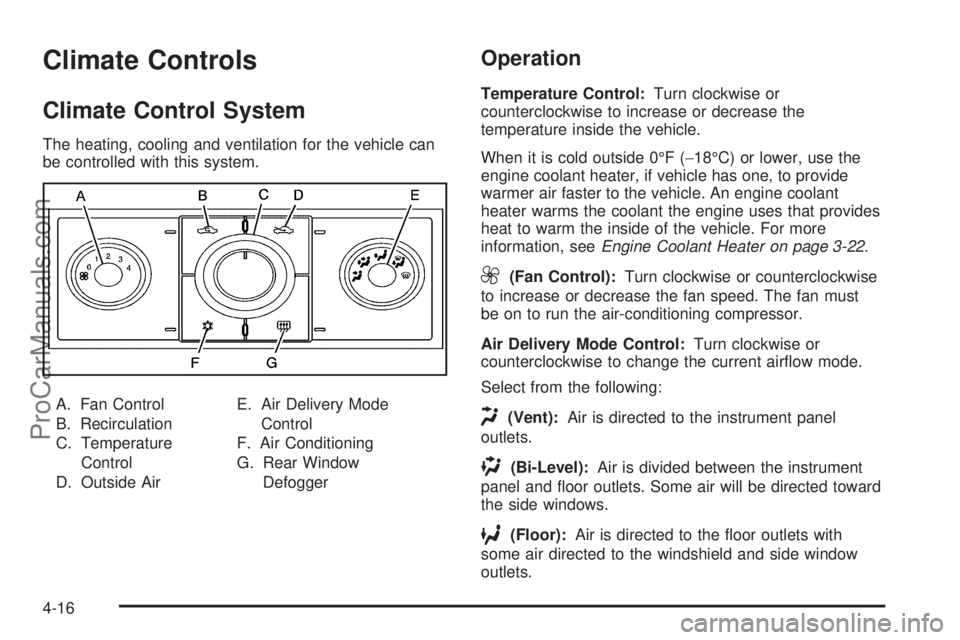
The heating, cooling and ventilation for the vehicle can
be controlled with this system.
A. Fan Control
B. Recirculation
C. Temperature
Control
D. Outside AirE. Air Delivery Mode
Control
F. Air Conditioning
G. Rear Window
Defogger
Operation
Temperature Control:Turn clockwise or
counterclockwise to increase or decrease the
temperature inside the vehicle.
When it is cold outside 0°F (−18°C) or lower, use the
engine coolant heater, if vehicle has one, to provide
warmer air faster to the vehicle. An engine coolant
heater warms the coolant the engine uses that provides
heat to warm the inside of the vehicle. For more
information, seeEngine Coolant Heater on page 3-22.
9(Fan Control):Turn clockwise or counterclockwise
to increase or decrease the fan speed. The fan must
be on to run the air-conditioning compressor.
Air Delivery Mode Control:Turn clockwise or
counterclockwise to change the current airflow mode.
Select from the following:
H(Vent):Air is directed to the instrument panel
outlets.
)(Bi-Level):Air is divided between the instrument
panel and floor outlets. Some air will be directed toward
the side windows.
6(Floor):Air is directed to the floor outlets with
some air directed to the windshield and side window
outlets.
4-16
ProCarManuals.com
Page 171 of 428
Remote Start Climate Control Operation
For vehicles with the remote start feature, when it
is activated the climate control system heats or cools
the inside of the vehicle using the modes that were set
before the vehicle was turned off. The climate control
knobs will remain active during a remote start. However,
the climate control buttons will be inactive until the
ignition is turned on by the key. If the fan is off,
the climate control system will not operate during remote
start. SeeRemote Keyless Entry (RKE) System
Operation on page 3-3.
Automatic Climate Control System
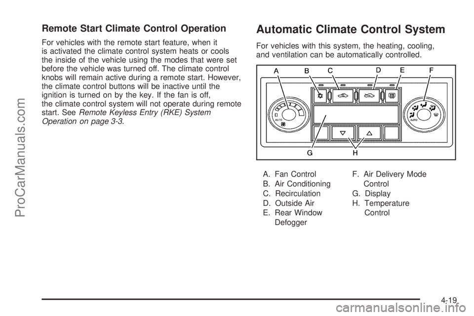
For vehicles with this system, the heating, cooling,
and ventilation can be automatically controlled.
A. Fan Control
B. Air Conditioning
C. Recirculation
D. Outside Air
E. Rear Window
DefoggerF. Air Delivery Mode
Control
G. Display
H. Temperature
Control
4-19
ProCarManuals.com
Page 172 of 428
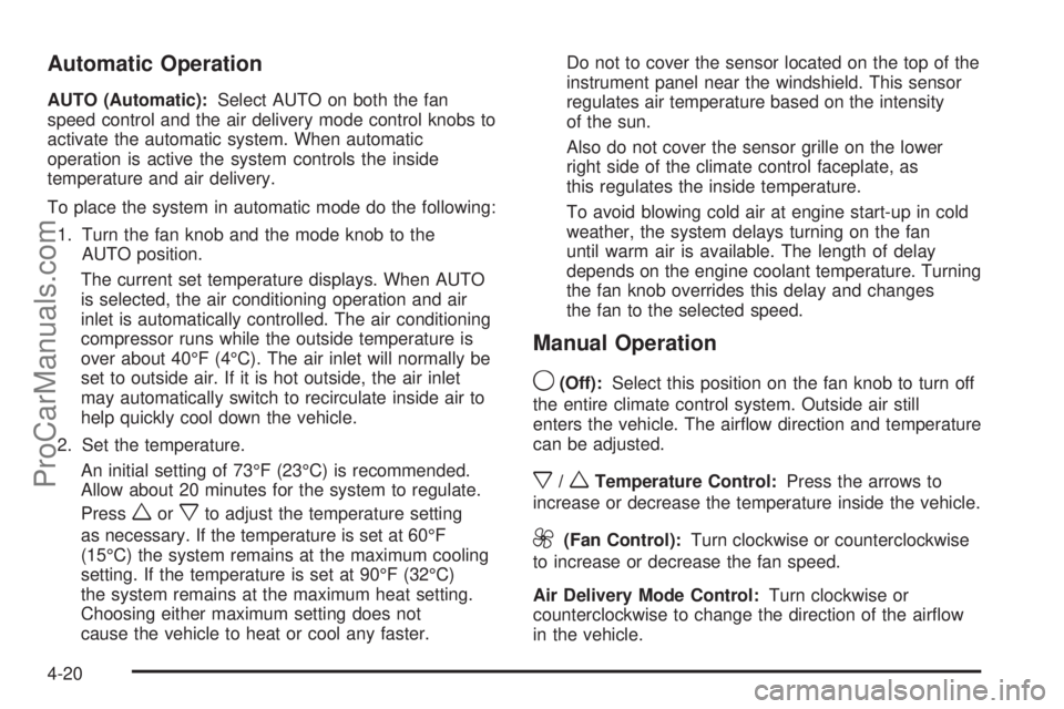
Automatic Operation
AUTO (Automatic):Select AUTO on both the fan
speed control and the air delivery mode control knobs to
activate the automatic system. When automatic
operation is active the system controls the inside
temperature and air delivery.
To place the system in automatic mode do the following:
1. Turn the fan knob and the mode knob to the
AUTO position.
The current set temperature displays. When AUTO
is selected, the air conditioning operation and air
inlet is automatically controlled. The air conditioning
compressor runs while the outside temperature is
over about 40°F (4°C). The air inlet will normally be
set to outside air. If it is hot outside, the air inlet
may automatically switch to recirculate inside air to
help quickly cool down the vehicle.
2. Set the temperature.
An initial setting of 73°F (23°C) is recommended.
Allow about 20 minutes for the system to regulate.
Press
worxto adjust the temperature setting
as necessary. If the temperature is set at 60°F
(15°C) the system remains at the maximum cooling
setting. If the temperature is set at 90°F (32°C)
the system remains at the maximum heat setting.
Choosing either maximum setting does not
cause the vehicle to heat or cool any faster.Do not to cover the sensor located on the top of the
instrument panel near the windshield. This sensor
regulates air temperature based on the intensity
of the sun.
Also do not cover the sensor grille on the lower
right side of the climate control faceplate, as
this regulates the inside temperature.
To avoid blowing cold air at engine start-up in cold
weather, the system delays turning on the fan
until warm air is available. The length of delay
depends on the engine coolant temperature. Turning
the fan knob overrides this delay and changes
the fan to the selected speed.
Manual Operation
9(Off):Select this position on the fan knob to turn off
the entire climate control system. Outside air still
enters the vehicle. The airflow direction and temperature
can be adjusted.
x/wTemperature Control:Press the arrows to
increase or decrease the temperature inside the vehicle.
9(Fan Control):Turn clockwise or counterclockwise
to increase or decrease the fan speed.
Air Delivery Mode Control:Turn clockwise or
counterclockwise to change the direction of the airflow
in the vehicle.
4-20
ProCarManuals.com
Page 175 of 428
Remote Start Climate Control Operation
For vehicles with remote start, when it is activated the
climate control system heats and cools the inside of
the vehicle using the previous system settings before the
vehicle was turned off. The climate control knobs will
remain active during a remote start. However, the
climate control buttons will be inactive until the ignition
is turned on by the key. If the fan is off, the climate
control system will not operate during remote start.
With the automatic climate control system, the climate
control displays “RS” in place of the temperature to
indicate that remote start is activated. For best
performance, turn both the fan and mode knobs to
AUTO. If the temperature is cold enough and the mode
knob is set to AUTO, the system begins in defrost to
clear the windows. SeeRemote Keyless Entry
(RKE) System Operation on page 3-3.
Outlet Adjustment
There are four main air outlets on the instrument panel.
Move the lever located in the center of each outlet
side-to-side or up and down, to change the direction and
amount of airflow in the vehicle. The center thumbwheel
does not control the main outlets.
Rear Seat Air Outlet
For vehicles with this feature, the rear seat air outlet is
located in the center of the instrument panel above
the two main center outlets.
Use the thumbwheel in the center of the outlet to turn
the airflow on or off.
4-23
ProCarManuals.com
Page 253 of 428

WARNING: (Continued)
If the vehicle is stuck in the snow:
•Clear away snow from around the base of
your vehicle, especially any that is blocking
the exhaust pipe.
•Check again from time to time to be sure
snow does not collect there.
•Open a window about 5 cm (two inches) on
the side of the vehicle that is away from the
wind to bring in fresh air.
•Fully open the air outlets on or under the
instrument panel.
•Adjust the Climate Control system to a setting
that circulates the air inside the vehicle and
set the fan speed to the highest setting. See
Climate Control System in the Index.
For more information about carbon monoxide, see
Engine Exhaust on page 3-30.
Snow can trap exhaust gases under your vehicle.
This can cause deadly CO (carbon monoxide) gas
to get inside. CO could overcome you and kill you.
You cannot see it or smell it, so you might not
know it is in your vehicle. Clear away snow from
around the base of your vehicle, especially any
that is blocking the exhaust.Run the engine for short periods only as needed to
keep warm, but be careful.
To save fuel, run the engine for only short periods as
needed to warm the vehicle and then shut the engine off
and close the window most of the way to save heat.
Repeat this until help arrives but only when you
feel really uncomfortable from the cold. Moving about to
keep warm also helps.
If it takes some time for help to arrive, now and then
when you run the engine, push the accelerator
pedal slightly so the engine runs faster than the idle
speed. This keeps the battery charged to restart
the vehicle and to signal for help with the headlamps.
Do this as little as possible to save fuel.
5-17
ProCarManuals.com
Page 332 of 428

Uniform Tire Quality Grading
Quality grades can be found where applicable on
the tire sidewall between tread shoulder and
maximum section width. For example:
Treadwear 200 Traction AA
Temperature A
The following information relates to the system
developed by the United States National Highway
Traffic Safety Administration (NHTSA), which
grades tires by treadwear, traction, and
temperature performance. This applies only to
vehicles sold in the United States. The grades are
molded on the sidewalls of most passenger car
tires. The Uniform Tire Quality Grading (UTQG)
system does not apply to deep tread, winter-type
snow tires, space-saver, or temporary use
spare tires, tires with nominal rim diameters of
10 to 12 inches (25 to 30 cm), or to some
limited-production tires.
While the tires available on General Motors
passenger cars and light trucks may vary with
respect to these grades, they must also conform
to federal safety requirements and additional
General Motors Tire Performance Criteria (TPC)
standards.
Treadwear
The treadwear grade is a comparative rating
based on the wear rate of the tire when tested
under controlled conditions on a specified
government test course. For example, a tire
graded 150 would wear one and a half (1.5) times
as well on the government course as a tire
graded 100. The relative performance of tires
depends upon the actual conditions of their use,
however, and may depart significantly from
the norm due to variations in driving habits, service
practices, and differences in road characteristics
and climate.
Traction – AA, A, B, C
The traction grades, from highest to lowest, are
AA, A, B, and C. Those grades represent the tire’s
ability to stop on wet pavement as measured
under controlled conditions on specified
government test surfaces of asphalt and concrete.
A tire marked C may have poor traction
performance.
6-62
ProCarManuals.com
Page 412 of 428

Arming the System.........................................3-16
Assistance Program, Roadside........................... 8-6
Audio System.........................................4-50, 4-69
Audio Steering Wheel Controls......................4-82
Radio Reception..........................................4-83
Rear Seat (RSA).........................................4-79
Setting the Clock.........................................4-51
Theft-Deterrent Feature................................4-81
XM™ Satellite Radio Antenna System............4-84
Audio System(s).............................................4-52
Automatic Climate Control System.....................4-19
Automatic Dimming Mirror Operation..................3-32
Automatic Headlamp System............................4-11
Automatic Transmission
Fluid..........................................................6-23
Operation...................................................3-23
Automatic Transmission Shift Lock Control
System Check.............................................. 7-8
B
Backglass Antenna..........................................4-84
Backing Up....................................................5-31
Battery..........................................................6-35
Electric Power Management..........................4-14
Run-Down Protection...................................4-14
Battery Replacement......................................... 3-5Belt Routing, Engine.......................................7-12
Blizzard Conditions..........................................5-16
Bluetooth Controls...........................................4-69
Bluetooth
®.....................................................4-68
Brake
Emergencies................................................ 5-5
Brake Adjustment............................................6-35
Brake Fluid....................................................6-33
Brake Pedal Travel.........................................6-35
Brake Wear...................................................6-34
Brakes..........................................................6-33
Antilock....................................................... 5-4
Parking......................................................3-26
System Warning Light..................................4-30
Braking........................................................... 5-3
Braking in Emergencies..................................... 5-5
Break-In, New Vehicle.....................................3-19
Bulb Replacement...........................................6-43
Fog Lamps .................................................4-12
Halogen Bulbs............................................6-41
Headlamp Aiming........................................6-40
Headlamps.................................................6-41
License Plate Lamps....................................6-43
Taillamps, Turn Signal, Sidemarker, Stoplamps,
and Back-Up Lamps.................................6-41
Buying New Tires...........................................6-60
2
ProCarManuals.com