warning SATURN AURA HYBRID 2010 Owners Manual
[x] Cancel search | Manufacturer: SATURN, Model Year: 2010, Model line: AURA HYBRID, Model: SATURN AURA HYBRID 2010Pages: 400, PDF Size: 2.46 MB
Page 1 of 400
In Brief........................................................... 1-1
Instrument Panel
........................................ 1-2
Initial Drive Information
............................... 1-3
Vehicle Features......................................1-17
Hybrid Features
.......................................1-22
Performance and Maintenance
...................1-24
Seats and Restraint System............................. 2-1
Head Restraints
......................................... 2-2
Front Seats
............................................... 2-3
Rear Seats
............................................... 2-9
Safety Belts.............................................2-11
Child Restraints
.......................................2-30
Airbag System.........................................2-56
Restraint System Check
............................2-73
Features and Controls..................................... 3-1
Keys........................................................ 3-2
Doors and Locks
....................................... 3-9
Windows
.................................................3-14
Theft-Deterrent Systems
............................3-17
Starting and Operating Your Vehicle
...........3-21
Mirrors
....................................................3-35
Storage Areas
.........................................3-36
Sunroof..................................................3-37
Instrument Panel............................................. 4-1
Instrument Panel Overview
.......................... 4-3
Climate Controls......................................4-16Warning Lights, Gages, and Indicators
........4-21
Driver Information Center (DIC)
..................4-37
Audio System(s).......................................4-51
Driving Your Vehicle....................................... 5-1
Your Driving, the Road, and the Vehicle
....... 5-2
Towing
...................................................5-25
Service and Appearance Care.......................... 6-1
Service
..................................................... 6-3
Fuel
......................................................... 6-6
Checking Things Under the Hood
...............6-12
Headlamp Aiming
.....................................6-39
Bulb Replacement
....................................6-39
Windshield Wiper Blade Replacement
.........6-42
Tires
......................................................6-43
Appearance Care
.....................................6-73
Vehicle Identification
.................................6-81
Electrical System
......................................6-82
Capacities and Specifications
.....................6-92
Maintenance Schedule..................................... 7-1
Maintenance Schedule
................................ 7-2
Customer Assistance Information.................... 8-1
Customer Assistance and Information........... 8-2
Reporting Safety Defects
...........................8-14
Vehicle Data Recording and Privacy
...........8-16
Index................................................................ 1
2010 Saturn AURA Hybrid Owner ManualM
ProCarManuals.com
Page 3 of 400
Safety Warnings and Symbols
Warning Messages found on vehicle labels and in this
manual describe hazards and what to do to avoid
or reduce them.
Dangerindicates a hazard with a high level of risk
which will result in serious injury or death.
WarningorCautionindicates a hazard that could result
in injury or death.
{WARNING:
These mean there is something that could hurt
you or other people.
Notice:This means there is something that could
result in property or vehicle damage. This would not
be covered by the vehicle’s warranty.A circle with a slash
through it is a safety
symbol which means “Do
Not,” “Do not do this,”
or “Do not let this happen.”
Vehicle Symbols
The vehicle has components and labels that use
symbols instead of text. Symbols are shown along with
the text describing the operation or information
relating to a specific component, control, message,
gage, or indicator.
M:This symbol is shown when you need to see your
owner manual for additional instructions or information.
*:This symbol is shown when you need to see a
service manual for additional instructions or information.
iii
ProCarManuals.com
Page 4 of 400
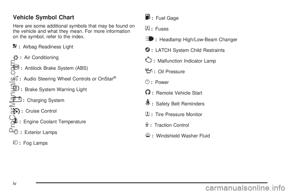
Vehicle Symbol Chart
Here are some additional symbols that may be found on
the vehicle and what they mean. For more information
on the symbol, refer to the index.
9:Airbag Readiness Light
#:Air Conditioning
!:Antilock Brake System (ABS)
g:Audio Steering Wheel Controls or OnStar®
$:Brake System Warning Light
":Charging System
I:Cruise Control
B:Engine Coolant Temperature
O:Exterior Lamps
#:Fog Lamps
.:Fuel Gage
+:Fuses
i:Headlamp High/Low-Beam Changer
j:LATCH System Child Restraints
*:Malfunction Indicator Lamp
::Oil Pressure
}:Power
/:Remote Vehicle Start
>:Safety Belt Reminders
7:Tire Pressure Monitor
F:Traction Control
M:Windshield Washer Fluid
iv
ProCarManuals.com
Page 7 of 400
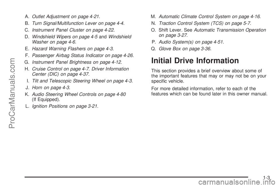
A.Outlet Adjustment on page 4-21.
B.Turn Signal/Multifunction Lever on page 4-4.
C.Instrument Panel Cluster on page 4-22.
D.Windshield Wipers on page 4-5andWindshield
Washer on page 4-6.
E.Hazard Warning Flashers on page 4-3.
F.Passenger Airbag Status Indicator on page 4-26.
G.Instrument Panel Brightness on page 4-12.
H.Cruise Control on page 4-7.Driver Information
Center (DIC) on page 4-37.
I.Tilt and Telescopic Steering Wheel on page 4-3.
J.Horn on page 4-3.
K.Audio Steering Wheel Controls on page 4-80
(If Equipped).
L.Ignition Positions on page 3-21.M.Automatic Climate Control System on page 4-16.
N.Traction Control System (TCS) on page 5-7.
O. Shift Lever. SeeAutomatic Transmission Operation
on page 3-27.
P.Audio System(s) on page 4-51.
Q.Glove Box on page 3-36.
Initial Drive Information
This section provides a brief overview about some of
the important features that may or may not be on your
specific vehicle.
For more detailed information, refer to each of the
features which can be found later in this owner manual.
1-3
ProCarManuals.com
Page 9 of 400
Starting the Vehicle
1. Aim the RKE transmitter at the vehicle.
2. Press
Q.
3. Immediately after completing Step 2, press and
hold
/until the turn signal lamps flash.
When the vehicle starts, the parking lamps will turn on
and remain on as long as the engine is running.
The doors will be locked and the climate control system
may come on.
The engine will continue to run for 10 minutes. Repeat
the steps for a 10-minute time extension. Remote
start can be extended only once.
Canceling a Remote Start
To cancel a remote start:
•Aim the RKE transmitter at the vehicle and press
and hold
/until the parking lamps turn off.
•Turn on the hazard warning flashers.
•Turn the ignition switch out of LOCK/OFF position
and then back to LOCK/OFF.
SeeRemote Vehicle Start on page 3-7.
1-5
ProCarManuals.com
Page 24 of 400

Driver Information Center (DIC)
The DIC display is located at the bottom of the
instrument panel cluster. It shows the status of many
vehicle systems and enables access to the
personalization menu.
The DIC buttons are
located on the left side of
the steering wheel.
INFO:Press to scroll through the vehicle information
displays.
r:Press to reset some vehicle information displays,
select a personalization setting, or acknowledge a
warning message.
For more information, seeDriver Information Center
(DIC) on page 4-37.
Vehicle Personalization
Some vehicle features can be programmed by using the
DIC buttons on the left side of the steering wheel.
These features include:
•Oil Life Reset
•Units
•RKE Lock and Unlock Feedback
•Door Lock and Unlock Settings
•Language
SeeDIC Vehicle Personalization on page 4-45.
1-20
ProCarManuals.com
Page 28 of 400

Battery
This vehicle has a standard 12-volt battery and a 36-volt
hybrid battery system.
The 36-volt battery is located behind the rear seat, in
the trunk. If the vehicle is to be stored for an extended
period of time, it should be driven at least every two
months or the 36-volt hybrid battery can be permanently
damaged. If a new 36-volt hybrid battery system is
needed, see your dealer/retailer. For important
information about the 36-volt hybrid battery, seeBattery
on page 6-34.
Service
Never try to do your own service on hybrid components.
You can be injured and the vehicle can be damaged
if you try to do your own service work. Service and
repair of these hybrid components should only be
performed by a trained service technician with the
proper knowledge and tools. SeeDoing Your Own
Service Work on page 6-4
Performance and Maintenance
Traction Control System (TCS)
The traction control system limits wheel spin. The
system turns on automatically every time the vehicle is
started.
•To turn off traction control, press and releaseton
the vertical surface in front of the center console
armrest.
Filluminates and the appropriate DIC
message displays. SeeDIC Warnings and
Messages on page 4-41.
•Press and release the button again to turn on
traction control.
For more information, seeTraction Control System
(TCS) on page 5-7.
1-24
ProCarManuals.com
Page 29 of 400
Electronic Stability Control (ESC)
The vehicle may have an Electronic Stability Control
system that assists with directional control of the vehicle
in difficult driving conditions. The system turns on
automatically every time the vehicle is started.
•To turn off both traction control and Electronic
Stability Control, press and hold
t, located on the
vertical surface in front of the center console
armrest, until
Filluminates and the appropriate DIC
message displays. SeeDIC Warnings and
Messages on page 4-41.
•Press and release the button again to turn on both
systems.
For more information, seeElectronic Stability Control
(ESC) on page 5-6.
Tire Pressure Monitor
This vehicle may have a Tire Pressure Monitor System
(TPMS).
The Tire Pressure Monitor
alerts you when a
significant reduction in
pressure occurs in one or
more of the vehicle’s
tires by illuminating the low
tire pressure warning
light on the instrument
cluster.
The warning light will remain on until the tire pressure is
corrected. The proper tire pressures for your vehicle
are listed on the Tire and Loading Information label
located on the driver side center pillar (B pillar). See
Loading the Vehicle on page 5-20.
You may notice during cooler conditions that the low tire
pressure warning light will appear when the vehicle is
first started and then turn off as you drive. This may be
an early indicator that your tire pressures are getting
low and the tires need to be inflated to the proper
pressure.
1-25
ProCarManuals.com
Page 30 of 400
Note:The Tire Pressure Monitor can alert you about
low tire pressure, but it does not replace normal monthly
tire maintenance. It is the driver’s responsibility to
maintain correct tire pressures.
SeeTire Pressure Monitor System on page 6-51and
Tire Pressure Monitor Operation on page 6-52.
Tire Sealant and Compressor Kit
This vehicle has a tire sealant and compressor kit which
can be used to seal small punctures in the tread area
of the tire.
SeeTire Sealant and Compressor Kit on page 6-66for
complete operating information.
Engine Oil Life System
The engine oil life system calculates engine oil life
based on vehicle use and displays a DIC message when
it is necessary to change the engine oil and filter. The
oil life system should be reset to 100% only following an
oil change.
Resetting the Oil Life System
1. Turn the ignition key to ON/RUN with the
engine off.
2. With the CHANGE OIL SOON message displayed,
press either of the DIC buttons to clear the
message. SeeDIC Warnings and Messages on
page 4-41.
3. Display OIL LIFE RESET on the DIC.
4. Press and hold the INFO button for at least one
second. An ACKNOWLEDGED message displays
for three seconds or until the next button is pressed.
This tells you the system has been reset. See
DIC Vehicle Personalization on page 4-45.
5. Turn the key to LOCK/OFF.
SeeEngine Oil Life System on page 6-18.
1-26
ProCarManuals.com
Page 36 of 400
Head Restraints
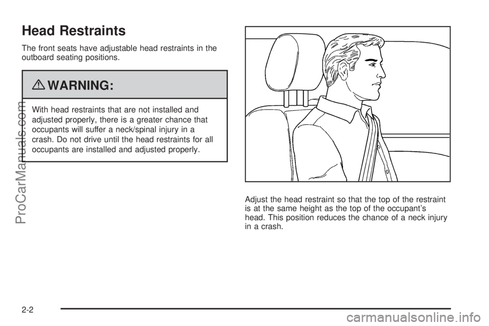
The front seats have adjustable head restraints in the
outboard seating positions.
{WARNING:
With head restraints that are not installed and
adjusted properly, there is a greater chance that
occupants will suffer a neck/spinal injury in a
crash. Do not drive until the head restraints for all
occupants are installed and adjusted properly.
Adjust the head restraint so that the top of the restraint
is at the same height as the top of the occupant’s
head. This position reduces the chance of a neck injury
in a crash.
2-2
ProCarManuals.com