power steering SATURN OUTLOOK 2009 Owners Manual
[x] Cancel search | Manufacturer: SATURN, Model Year: 2009, Model line: OUTLOOK, Model: SATURN OUTLOOK 2009Pages: 432, PDF Size: 2.48 MB
Page 4 of 432
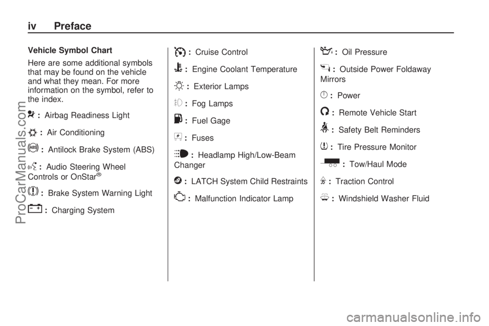
Vehicle Symbol Chart
Here are some additional symbols
that may be found on the vehicle
and what they mean. For more
information on the symbol, refer to
the index.
9:Airbag Readiness Light
#:Air Conditioning
!:Antilock Brake System (ABS)
g:Audio Steering Wheel
Controls or OnStar®
$:Brake System Warning Light
":Charging System
I:Cruise Control
B:Engine Coolant Temperature
O:Exterior Lamps
#:Fog Lamps
.:Fuel Gage
+:Fuses
i:Headlamp High/Low-Beam
Changer
j:LATCH System Child Restraints
*:Malfunction Indicator Lamp
::Oil Pressure
g:Outside Power Foldaway
Mirrors
}:Power
/:Remote Vehicle Start
>:Safety Belt Reminders
7:Tire Pressure Monitor
_:Tow/Haul Mode
F:Traction Control
M:Windshield Washer Fluid
iv Preface
ProCarManuals.com
Page 87 of 432
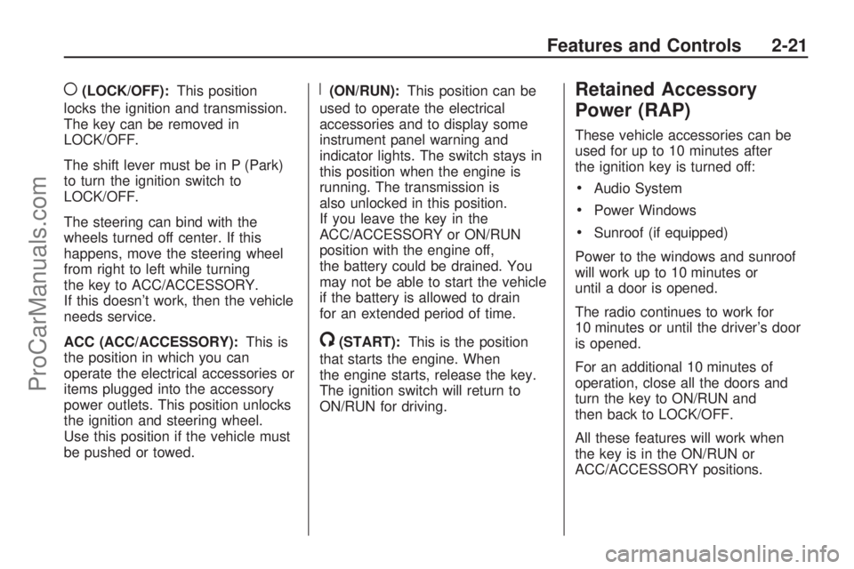
((LOCK/OFF):This position
locks the ignition and transmission.
The key can be removed in
LOCK/OFF.
The shift lever must be in P (Park)
to turn the ignition switch to
LOCK/OFF.
The steering can bind with the
wheels turned off center. If this
happens, move the steering wheel
from right to left while turning
the key to ACC/ACCESSORY.
If this doesn’t work, then the vehicle
needs service.
ACC (ACC/ACCESSORY):This is
the position in which you can
operate the electrical accessories or
items plugged into the accessory
power outlets. This position unlocks
the ignition and steering wheel.
Use this position if the vehicle must
be pushed or towed.R(ON/RUN):This position can be
used to operate the electrical
accessories and to display some
instrument panel warning and
indicator lights. The switch stays in
this position when the engine is
running. The transmission is
also unlocked in this position.
If you leave the key in the
ACC/ACCESSORY or ON/RUN
position with the engine off,
the battery could be drained. You
may not be able to start the vehicle
if the battery is allowed to drain
for an extended period of time.
/(START):This is the position
that starts the engine. When
the engine starts, release the key.
The ignition switch will return to
ON/RUN for driving.
Retained Accessory
Power (RAP)
These vehicle accessories can be
used for up to 10 minutes after
the ignition key is turned off:
Audio System
Power Windows
Sunroof (if equipped)
Power to the windows and sunroof
will work up to 10 minutes or
until a door is opened.
The radio continues to work for
10 minutes or until the driver’s door
is opened.
For an additional 10 minutes of
operation, close all the doors and
turn the key to ON/RUN and
then back to LOCK/OFF.
All these features will work when
the key is in the ON/RUN or
ACC/ACCESSORY positions.
Features and Controls 2-21
ProCarManuals.com
Page 110 of 432

OnStar Virtual Advisor
OnStar Virtual Advisor is a feature of
OnStar Hands-Free Calling that uses
minutes to access location-based
weather, local traffic reports, and
stock quotes. Press the phone button
and give a few simple voice
commands to browse through the
various topics. See the OnStar
Owner’s Guide for more information.
This feature is only available in the
continental U.S.
OnStar Steering Wheel
Controls
This vehicle may have a Talk/Mute
button that can be used to
interact with OnStar Hands-Free
Calling. SeeAudio Steering Wheel
Controls on page 3-125for more
information.
On some vehicles, the mute button
can be used to dial numbers into
voice mail systems, or to dial phone
extensions. See the OnStar Owner’s
Guide for more information.
How OnStar Service Works
The OnStar system can record and
transmit vehicle information. This
information is automatically sent to
an OnStar Call Center when the
OnStar button is pressed, the
emergency button is pressed, or if
the airbags or AACN system deploy.
This information usually includes the
vehicle’s GPS location and, in the
event of a crash, additional
information regarding the crash that
the vehicle was involved in (e.g. the
direction from which the vehicle was
hit). When the Virtual Advisor feature
of OnStar Hands-Free Calling is
used, the vehicle also sends OnStar
the vehicle’s GPS location so they
can provide services where it is
located.
OnStar service cannot work unless
the vehicle is in a place where
OnStar has an agreement with a
wireless service provider for service
in that area. OnStar service also
cannot work unless the vehicle is ina place where the wireless service
provider OnStar has hired for that
area has coverage, network capacity
and reception when the service is
needed, and technology that is
compatible with the OnStar service.
Not all services are available
everywhere, particularly in remote or
enclosed areas, or at all times.
Location information about
the vehicle is only available if the
GPS satellite signals are
unobstructed and available.
The vehicle must have a working
electrical system, including adequate
battery power, for the OnStar
equipment to operate. There are
other problems OnStar cannot
control that may prevent OnStar from
providing OnStar service at any
particular time or place. Some
examples are damage to important
parts of the vehicle in a crash, hills,
tall buildings, tunnels, weather or
wireless phone network congestion.
2-44 Features and Controls
ProCarManuals.com
Page 123 of 432
Instrument Panel
Instrument Panel OverviewInstrument Panel Overview.....3-4
Hazard Warning Flashers.......3-5
Horn....................................3-5
Tilt and Telescopic Steering
Wheel................................3-6
Turn Signal/Multifunction
Lever.................................3-6
Turn and Lane-Change
Signals...............................3-6
Headlamp High/Low-Beam
Changer.............................3-7
Flash-to-Pass........................3-7
Windshield Wipers.................3-7
Windshield Washer................3-8
Rear Window Wiper/Washer. . . .3-9
Cruise Control......................3-9
Exterior Lamps....................3-11
Delayed Headlamps.............3-12
Daytime Running
Lamps (DRL)/Automatic
Headlamp System..............3-12
Fog Lamps.........................3-13Instrument Panel
Brightness.........................3-13
Courtesy Lamps..................3-13
Dome Lamps......................3-14
Dome Lamp Override...........3-14
Entry Lighting......................3-14
Delayed Entry Lighting.........3-14
Delayed Exit Lighting...........3-15
Parade Dimming..................3-15
Reading Lamps...................3-15
Electric Power
Management.....................3-15
Battery Run-Down
Protection.........................3-16
Accessory Power Outlet(s). . . .3-17
Power Outlet 115 Volt
Alternating Current.............3-18
Climate ControlsClimate Control System........3-19
Dual Automatic Climate
Control System..................3-22
Outlet Adjustment................3-27
Rear Air Conditioning and
Heating System.................3-28
Rear Air Conditioning and
Heating System and
Electronic Climate
Controls............................3-29
Warning Lights, Gages,
and Indicators
Warning Lights, Gages,
and Indicators...................3-30
Instrument Panel Cluster.......3-31
Speedometer and
Odometer.........................3-32
Tachometer........................3-32
Safety Belt Reminders..........3-32
Airbag Readiness Light.........3-33
Passenger Airbag Status
Indicator...........................3-34
Charging System Light.........3-35
Voltmeter Gage...................3-35
Brake System Warning
Light................................3-36
Antilock Brake System
(ABS) Warning Light...........3-37
StabiliTrak
®Indicator Light.....3-37
Engine Coolant Temperature
Warning Light....................3-38
Engine Coolant
Temperature Gage.............3-38
Tire Pressure Light..............3-39
Malfunction
Indicator Lamp..................3-39
Oil Pressure Light................3-42
Security Light......................3-43
Fog Lamp Light...................3-43
Instrument Panel 3-1
ProCarManuals.com
Page 127 of 432

The main components of the
instrument panel are listed here:
A.Outlet Adjustment on page 3-27.
B.Turn Signal/Multifunction
Lever on page 3-6.
C.Instrument Panel Cluster on
page 3-31.
D.Driver Information Center (DIC)
on page 3-44.
E.Instrument Panel Storage on
page 2-50.
F.Audio System(s) on page 3-74.
Navigation/Radio System on
page 3-103(If Equipped).
G.Exterior Lamps on page 3-11.
H.Hood Release on page 5-11.
I.Dome Lamp Override on
page 3-14.Instrument Panel
Brightness on page 3-13.
J.Cruise Control on page 3-9.
K.Tilt and Telescopic Steering
Wheel on page 3-6.
L.Horn on page 3-5.M.Audio Steering Wheel Controls
on page 3-125.
N.Hazard Warning Flashers on
page 3-5.
O. Center Console Shift Lever.
See “Console Shift Lever” under
Shifting Into Park on page 2-28.
P.Rear Window Wiper/Washer
on page 3-9. Traction Control
System (TCS) Disable Button
(If Equipped). SeeStabiliTrak
®
System on page 4-5.Tow/Haul
Mode on page 2-26(If Equipped).
Power Liftgate on page 2-11
(If Equipped).
Q.Accessory Power Outlet(s) on
page 3-17.
R.Heated Seats on page 1-5.
S.Dual Automatic Climate Control
System on page 3-22.
T. Passenger Air Bag Status
Indicator. SeePassenger
Sensing System on page 1-55.
U.Glove Box on page 2-50.
Hazard Warning Flashers
|
Hazard Warning Flasher:Press
this button located on the instrument
panel below the audio system, to
make the front and rear turn signal
lamps �ash on and off. This warns
others that you are having trouble.
Press again to turn the �ashers off.
The turn signals do not work while
the hazard warning �ashers are on.
Horn
Press near or on the horn symbols
on the steering wheel pad to
sound the horn.
Instrument Panel 3-5
ProCarManuals.com
Page 184 of 432

SERVICE BATTERY
CHARGING SYSTEM
On some vehicles, this message
displays if there is a problem
with the battery charging system.
Under certain conditions, the
charging system light may also turn
on in the instrument panel cluster.
SeeCharging System Light on
page 3-35. Driving with this problem
could drain the battery. Turn off all
unnecessary accessories. Have the
electrical system checked as soon
as possible. See your dealer/retailer.
SERVICE BRAKE SYSTEM
This message displays along with
the brake system warning light if
there is a problem with the brake
system. SeeBrake System Warning
Light on page 3-36. If this message
appears, stop as soon as possible
and turn off the vehicle. Restart the
vehicle and check for the message
on the DIC display. If the message isstill displayed or appears again when
you begin driving, the brake system
needs service as soon as possible.
See your dealer/retailer.
SERVICE PARK ASSIST
If your vehicle has the Ultrasonic
Rear Parking Assist (URPA) system,
this message displays if there is a
problem with the URPA system.
Do not use this system to help you
park. SeeUltrasonic Rear Parking
Assist (URPA) on page 2-34for more
information. See your dealer/retailer
for service.
SERVICE POWER STEERING
This message displays when a
problem is detected with the power
steering system. When this message
is displayed, you may notice that the
effort required to steer the vehicle
increases or feels heavier, but you
will still be able to steer the vehicle.
Have your vehicle serviced by your
dealer/retailer immediately.
SERVICE STABILITRAK
This message displays if there
is a problem with the StabiliTrak®
system. If this message appears,
try to reset the system. Stop; turn off
the engine for at least 15 seconds;
then start the engine again. If this
message still comes on, it means
there is a problem. See your dealer/
retailer for service. The vehicle is
safe to drive, however, you do not
have the bene�t of StabiliTrak,
so reduce your speed and drive
accordingly.
SERVICE THEFT DETERRENT
SYSTEM
This message displays when there
is a problem with the theft-deterrent
system. The vehicle may or may
not restart so you may want to take
the vehicle to your dealer/retailer
before turning off the engine.
SeePASS-Key
®III+ Electronic
Immobilizer Operation on page 2-18
for more information.
3-62 Instrument Panel
ProCarManuals.com
Page 255 of 432

As the brakes are applied, the
computer keeps receiving updates
on wheel speed and controls braking
pressure accordingly.
Remember: ABS does not change
the time needed to get a foot
up to the brake pedal or always
decrease stopping distance. If you
get too close to the vehicle in
front of you, there will not be enough
time to apply the brakes if that
vehicle suddenly slows or stops.
Always leave enough room up
ahead to stop, even with ABS.
Using ABS
Do not pump the brakes. Just hold
the brake pedal down �rmly and
let antilock work. The antilock pump
or motor operating might be
heard and the brake pedal might be
felt to pulsate, but this is normal.
Braking in Emergencies
ABS allows the driver to steer and
brake at the same time. In many
emergencies, steering can help more
than even the very best braking.
Brake Assist
This vehicle has a Brake Assist
feature designed to assist the driver
in stopping or decreasing vehicle
speed in emergency driving
conditions. This feature uses the
stability system hydraulic brake
control module to supplement the
power brake system under
conditions where the driver has
quickly and forcefully applied
the brake pedal in an attempt to
quickly stop or slow down the
vehicle. The stability system
hydraulic brake control module
increases brake pressure at each
corner of the vehicle until the
ABS activates. Minor brake pedal
pulsations or pedal movement
during this time is normal and the
driver should continue to apply
the brake pedal as the drivingsituation dictates The Brake Assist
feature will automatically disengage
when the brake pedal is released
or brake pedal pressure is quickly
decreased.
StabiliTrak®System
The vehicle has the StabiliTrak
system which combines antilock
brake, traction and stability control
systems and helps the driver
maintain directional control of the
vehicle in most driving conditions.
When you �rst start the vehicle and
begin to drive away, the system
performs several diagnostic checks
to ensure there are no problems.
The system may be heard or
felt while it is working. This is normal
and does not mean there is a
problem with the vehicle. The
system should initialize before the
vehicle reaches 20 mph (32 km/h).
In some cases, it may take
approximately two miles (3.2 km) of
driving before the system initializes.
Driving Your Vehicle 4-5
ProCarManuals.com
Page 258 of 432

All-Wheel Drive (AWD)
System
If the vehicle has this feature, engine
power is sent to all four wheels when
extra traction is needed. This is like
four-wheel drive, but there is no
separate lever or switch to engage or
disengage the axle. It is fully
automatic, and adjusts itself as
needed for road conditions.
When using a compact spare tire on
the AWD equipped vehicle, the AWD
system automatically detects the
presence of the compact spare and
the AWD is disabled. To restore the
AWD operation and prevent
excessive wear on the AWD system,
replace the compact spare with a
full-size tire as soon as possible. See
Compact Spare Tire on page 5-83
for more information.
Steering
Power Steering
If power steering assist is lost
because the engine stops or the
system is not functioning, the vehicle
can be steered but it will take
more effort.
Variable Effort Steering
If the vehicle has this steering
system, the system continuously
adjusts the effort felt when steering
at all vehicle speeds. It provides
ease when parking, yet a �rm, solid
feel at highway speeds.
Steering Tips
It is important to take curves at a
reasonable speed.
Traction in a curve depends on the
condition of the tires and the road
surface, the angle at which the curve
is banked, and vehicle speed. While
in a curve, speed is the one factor
that can be controlled.
If there is a need to reduce speed,
do it before entering the curve,
while the front wheels are straight.
Try to adjust the speed so you
can drive through the curve.
Maintain a reasonable, steady
speed. Wait to accelerate until out
of the curve, and then accelerate
gently into the straightaway.
4-8 Driving Your Vehicle
ProCarManuals.com
Page 285 of 432
The seven-wire harness contains
the following trailer circuits:
Yellow: Left Stop/Turn Signal
Dark Green: Right Stop/Turn
Signal
Brown: Taillamps
Black: Ground
Light Green: Back-up Lamps
Red/Black: Battery Feed
Dark Blue: Trailer Brake*
*The fuse for this circuit is installed
in the underhood electrical center,
but the wires are not connected.
They should be connected by your
dealer/retailer or a quali�ed
service center.
If the back-up lamp circuit is not
functional, contact your
dealer/retailer.If a remote (non-vehicle) battery is
being charged, press the Tow/Haul
mode switch located on the
center console near the climate
controls. This will boost the vehicle
system voltage and properly
charge the battery. If the trailer is
too light for Tow/Haul mode, turn on
the headlamps (Non-HID only) as
a second way to boost the
vehicle system and charge the
battery.
Electric Trailer Brake Control
Wiring Provisions
These wiring provisions for an
electric trailer brake controller are
included with the vehicle as
part of the trailer wiring package.
The instrument panel contains blunt
cut wires behind the steering
column for the electric trailer brake
controller. The harness contains
the following wires:
Red/Black: Power Supply
White: Brake Switch Signal
Gray: Illumination
Dark Blue: Trailer Brake Signal
Black: Ground
The electric trailer brake controller
should be installed by your
dealer/retailer or a quali�ed service
center.
Engine Cooling When Trailer
Towing
The cooling system may temporarily
overheat during severe operating
conditions. SeeEngine Overheating
on page 5-23.
Driving Your Vehicle 4-35
ProCarManuals.com
Page 287 of 432
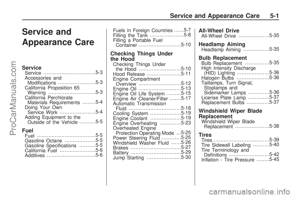
Service and
Appearance Care
ServiceService................................5-3
Accessories and
Modi�cations.......................5-3
California Proposition 65
Warning.............................5-3
California Perchlorate
Materials Requirements........5-4
Doing Your Own
Service Work......................5-4
Adding Equipment to the
Outside of the Vehicle..........5-5
FuelFuel....................................5-5
Gasoline Octane...................5-5
Gasoline Speci�cations..........5-5
California Fuel......................5-6
Additives..............................5-6Fuels in Foreign Countries......5-7
Filling the Tank.....................5-8
Filling a Portable Fuel
Container..........................5-10
Checking Things Under
the Hood
Checking Things Under
the Hood..........................5-10
Hood Release.....................5-11
Engine Compartment
Overview..........................5-12
Engine Oil..........................5-13
Engine Oil Life System.........5-15
Engine Air Cleaner/Filter.......5-17
Automatic Transmission
Fluid................................5-18
Cooling System...................5-19
Engine Coolant...................5-19
Engine Overheating.............5-23
Overheated Engine
Protection Operating Mode. . .5-25
Power Steering Fluid............5-25
Windshield Washer Fluid......5-26
Brakes...............................5-27
Battery...............................5-29
Jump Starting.....................5-30
All-Wheel DriveAll-Wheel Drive...................5-35
Headlamp AimingHeadlamp Aiming................5-35
Bulb ReplacementBulb Replacement...............5-35
High Intensity Discharge
(HID) Lighting....................5-36
Halogen Bulbs....................5-36
Taillamps, Turn Signal,
Stoplamps and
Sidemarker Lamps.............5-36
License Plate Lamp.............5-37
Replacement Bulbs..............5-37
Windshield Wiper Blade
Replacement
Windshield Wiper Blade
Replacement.....................5-38
TiresTires..................................5-39
Tire Sidewall Labeling..........5-40
Tire Terminology and
De�nitions.........................5-42
In�ation - Tire Pressure........5-45
Service and Appearance Care 5-1
ProCarManuals.com