trailer Seat Alhambra 2014 Owner's Guide
[x] Cancel search | Manufacturer: SEAT, Model Year: 2014, Model line: Alhambra, Model: Seat Alhambra 2014Pages: 381, PDF Size: 5.75 MB
Page 244 of 381
242Trailer towing
●The vehicle centre of gravity and handling change because of the trailer
load and because of the increased combined mass of the vehicle and trail-
er.
● If the towing vehicle is empty and the trailer loaded then the load distri-
bution is incorrect. If you must travel in these conditions, drive carefully and
reduce your speed accordingly.
Hill starts with a trailer
Depending on the hill and the gross combined weight, it is possible that the
combined vehicle and trailer move backwards slightly when starting.
For a hill start with a trailer, proceed as follows:
● Press and hold the brake pedal.
● Press the button
once to turn off the electric parking brake
⇒ page 185.
● Press and hold the button
to hold the vehicle and trailer combination
using the parking brake.
● With a manual gearbox: press the clutch pedal to the floor.
● Engage first gear or the gear range D ⇒ page 176, Changing gear.
● Release the brake pedal.
● Move off slowly. To do this, gently release the clutch pedal (for manual
gearbox).
● Release the button
only when the engine provides sufficient power
to move the vehicle and trailer combination.
WARNING
Jerking the trailer in an unsuitable manner could cause loss of vehicle
control with the subsequent serious consequences.
● Driving with a trailer and transporting heavy or a large objects will
change the vehicle handling and braking distances.
WARNING (Continued)
● Anticipate traffic and be extremely cautious. Brake early.
● Adjust your speed and driving style to visibility, road, traffic and
weather conditions. Reduce your speed, especially on steep hills.
● Accelerate gently and carefully. Avoid brusque manoeuvres and sud-
den braking.
● Always take the following precautions seriously. Reduce your speed
immediately if you observe the trailer rocking from side to side.
● Never try to stop the “snaking” by increasing speed.
● Always take the speed limits for vehicles with and without trailers in
each country into account.
Stabilising the vehicle and trailer combination
Stabilisation of the vehicle and trailer combination is an extension of the
electronic stability control (ESC) and helps, with the assistance of the trajec-
tory control, to reduce trailer “snaking”.
Stabilisation of the vehicle and trailer combination is active when the ESC
indicator on the dash panel remains lit for about two seconds more than the
ABS indicator.
Requirements for stabilising the vehicle/trailer combination
● An original tow hitch is fitted by the manufacturer or a compatible model
is retrofitted.
● The ECS is switched on. The warning lamp on the instrument panel is
not lit.
● The trailer is connected to the vehicle using the power socket.
● Driving faster than 60 km/h (37 mph).
● The maximum drawbar load is used.
Page 245 of 381
243
Trailer towing
● The trailer must have a fixed drawbar.
● Trailers with brakes must be equipped with a mechanical inertia brake.
WARNING
Do not let the extra safety afforded by the stabilisation system tempt you
into taking any risks when driving.
● Adjust your speed and driving style to visibility, road, traffic and
weather conditions.
● If the road surface is slippery, take care when accelerating.
● When a system is operating, lift your foot off the accelerator.
WARNING
It is possible that the combination stabilisation system does not correct-
ly recognised all driving situations.
● It is possible that the stabilisation system does not detect snaking of
a light trailer and thus does not intervene.
● When driving on slippery ground, the trailer could jack-knife despite
the stabilisation system.
● Trailers with a high centre of gravity may even tip over before they
start to rock sideways.
● If a trailer is not used and the trailer power socket is connected (for
example, installation of a bicycle carrier with lights), repeated automatic
braking may occur in extreme driving conditions.
Retrofitting a tow hitch
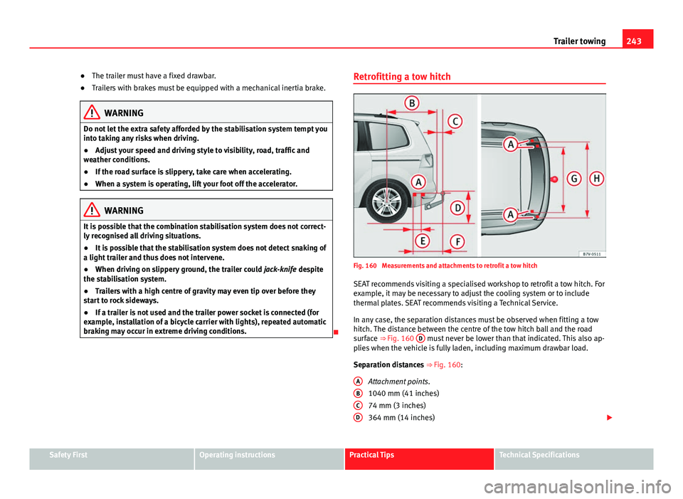
Fig. 160 Measurements and attachments to retrofit a tow hitch
SEAT recommends visiting a specialised workshop to retrofit a tow hitch. For
example, it may be necessary to adjust the cooling system or to include
thermal plates. SEAT recommends visiting a Technical Service.
In any case, the separation distances must be observed when fitting a tow
hitch. The distance between the centre of the tow hitch ball and the road
surface ⇒ Fig. 160 D
must never be lower than that indicated. This also ap-
plies when the vehicle is fully laden, including maximum drawbar load.
Separation distances ⇒ Fig. 160:
Attachment points.
1040 mm (41 inches)
74 mm (3 inches)
364 mm (14 inches)
A
BCD
Safety FirstOperating instructionsPractical TipsTechnical Specifications
Page 246 of 381
244Trailer towing
247 mm (10 inches)
596 mm (23 inches)
1,097 mm (43 inches)
1102 mm (43 inches)
WARNING
Erroneous or unsuitable connection of electric cables may cause anoma-
lies in the vehicle electronics that could result in an accident with serious
consequences.
● Never connect the trailer's electric system to the electrical connec-
tions of the rear lights or any other unsuitable power sources. Only use
suitable connectors to connect a trailer.
● Visit a specialised workshop if you wish to retrofit a tow hitch to the
vehicle.
WARNING
If the tow hitch is badly fitted or unsuitable, the trailer may separate from
the vehicle while driving. This could result in a serious accident.
Note
Use only tow hitches approved by SEAT for the vehicle.
Maximum gross trailer weight
The instructions in the official vehicle documents take precedence. All the
technical data provided in this documentation is applicable to the basic
model. The vehicle data label in the Maintenance Programme or the vehicle
documentation shows which engine is installed in your vehicle. E
FGH
The figures may be different depending whether additional equipment is fit-
ted, for different models and for special vehicles.
WARNING
Exceeding the maximum trailer weight indicated could cause a serious
accident.
● Never exceed the indicated trailer weight.
CAUTION
Exceeding the maximum trailer weight indicated could cause damage to the
vehicle.
● Never exceed the indicated trailer weight.
Gross combined vehicle weight rating
The instructions in the official vehicle documents take precedence. All the
technical data provided in this documentation is applicable to the basic
model. The vehicle data label in the Maintenance Programme or the vehicle
documentation shows which engine is installed in your vehicle.
The figures may be different depending whether additional equipment is fit-
ted, for different models and for special vehicles.
The maximum combined weights listed are only applicable for altitudes up
to 1000 m above sea level. The weight of the car and trailer must be re-
duced by about 10% for every further 1000 m (or part thereof).
WARNING
Exceeding the maximum weight indicated could cause a serious accident.
● Never exceed the gross combined weight rating.
Page 247 of 381
245
Trailer towing
CAUTION
Exceeding the maximum gross combined weight rating indicated could
cause damage to the vehicle.
● Never exceed the gross combined weight rating.
Safety FirstOperating instructionsPractical TipsTechnical Specifications
Page 288 of 381

286Checking and refilling levels
● Unscrew the cap from engine oil filler neck on the cylinder head
⇒ Fig. 172. If you are not sure where the cap is, request help from a special-
ist.
● Only refill using engine oil expressly approved by SEAT and in small
quantities (not more than 0.5 l or 1/2 a quarter of a gallon at a time)
⇒ page 284.
● To avoid adding too much oil, each time you add a quantity, wait until
the oil has flowed into the crankcase so that it can be measured with the
dipstick.
● Check the oil level before adding any more oil. Do not top up with too
much engine oil ⇒
.
● When the oil level is in at least the ⇒ Fig. 171 B zone, insert the dip-
stick into the tube fully to avoid engine oil escaping when the engine is run-
ning.
● After topping up the oil, ensure that the cap is screwed on to the filler
neck correctly.
WARNING
Oil could catch fire if it comes into contact with hot engine components.
This could lead to a fire, explosion and severe injuries.
● Always ensure that after topping of oil, the engine oil filler cap is cor-
rectly tightened. This will avoid engine oil spilling onto hot engine parts
when the engine is running.
CAUTION
● If the engine oil level is above the area ⇒ Fig. 171 A do not start the
engine. Seek specialist assistance. Otherwise catalytic converter and en-
gine damage may occur.
● When refilling or changing service liquids, ensure that you put the liq-
uids into the right tank. Making a mistake when refilling could cause seri-
ous malfunctions and damage the engine!
For the sake of the environment
The oil level must never be above area ⇒ Fig. 171 A. Otherwise oil can be
drawn in through the crankcase breather and escape into the atmosphere
via the exhaust system.
Engine oil consumption
The consumption of engine oil can be different from one engine to another
and can vary during the useful life of the engine.
Depending on driving style and the conditions of use, the consumption of
engine oil can reach 1 litre every 2000 km (one quarter of a gallon every
1200 miles); for new vehicles, this could be higher for the first 5000 km
(3000 miles). For this reason the engine oil level must be checked at regular
intervals, preferably when filling the tank and before a journey.
When the engine is working hard, for instance during sustained high-speed
motorway cruising in summer, when towing a trailer or climbing mountain
passes, the oil level should preferably be kept within area ⇒ Fig. 171 A
.
Changing the engine oil
The engine oil must be changed regularly according to the specifications of
the Maintenance Programme.
Due to the problems linked with disposing of used oil and the need for suit-
able tools and special knowledge, always visit a specialised workshop to
have the engine oil and filter changed. SEAT recommends visiting a Techni-
cal Service.
Detailed information on the service intervals are shown in the Maintenance
Programme.
Page 312 of 381
310Wheels and tyres
Changing a wheel*
Introduction
The tyres mounted on the vehicle are anti-puncture. The wheels should only
be changed when switching from summer to winter tyres or vice-versa. See
⇒ page 303
You should only change the wheels yourself if the vehicle is parked in a safe
place, you are familiar with the procedure and you have all the necessary
tools! Otherwise, you should seek professional assistance.
Additional information and warnings:
● Vehicle key set ⇒ page 72
● Wheels and tyres ⇒ page 297
● Wheel trims ⇒ page 308
● Vehicle tools ⇒ page 324
WARNING
Changing a wheel can be dangerous, especially on the hard shoulder.
Please observe the following rules to minimise the risk of injury:
● Stop the vehicle safely as soon as possible. Park your vehicle as safe
distance from surrounding traffic to change a wheel.
● When changing a wheel, keep all passengers and particularly chil-
dren a safe distance away from the work area.
● Turn on the hazard warning lights to warn other road users.
● Ensure the ground on which you park is flat and solid. If necessary,
support the jack on a wide solid base.
● If you are changing a wheel yourself, you should be familiar with the
required procedure. Otherwise, you should seek professional assistance.
WARNING (Continued)
● Only use suitable tools that are not damaged when changing a wheel.
● Always stop the engine, turn on the electronic parking brake and
place the gear selector lever in position P, for an automatic gearbox, or
engage a gear for a manual gearbox to reduce the risk of the vehicle mov-
ing accidentally.
● Have the tightening torque of the wheel bolts checked as soon as
possible with a reliable torque wrench.
Preparations for changing a wheel
Check list
Before changing a wheel, complete the following operations in the order
given ⇒
:
Park the vehicle on an even and solid surface.
Connect the electronic parking brake ⇒ page 185.
Automatic gearbox: move the selector lever to position P ⇒ page 176.
Stop the engine and remove the key from the ignition ⇒ page 172.
Manual gearbox: Select a gear ⇒ page 176.
Have all vehicle occupants get out of the vehicle and wait in a safe
place (for example, behind the safety barrier).
Block the opposite wheel with wedges or a similar object.
When towing a trailer: unhook the trailer from the towing vehicle and
park it correctly.
If the luggage compartment is full: take the baggage out of the vehicle. Take the vehicle tool kit out of the luggage compartment.
Remove the wheel trims ⇒ page 308.
1.
2.
3.
4.
5.
6.
7.
8.
9.
10.
11.
Page 316 of 381
314Wheels and tyres
Check list
For your own safety and that of other passengers, the following points
should be observed in the order given ⇒
:
Select a suitable flat and firm surface for raising the vehicle.
Switch off the engine, engage a gear (manual gearbox) or place the se-
lector lever in position P ⇒ page 176 and turn on the electronic parking
brake ⇒ page 185.
When towing a trailer: unhook the trailer from the towing vehicle and
park it correctly.
Loosen the wheel bolts on the wheel to be changed ⇒ page 311.
Look below the vehicle for the jacking point ⇒ Fig. 186 closest to the
tyre which has to be changed.
Raise the jack with the handle until it can be inserted below the jacking
point.
Ensure that the foot of the jack is firmly on the ground and that it is
placed immediately below the lifting point on the vehicle ⇒ Fig. 187.
Straighten the jack and continue raising it using the handle until the
claw holds the vertical reinforcement beneath the vehicle ⇒ Fig. 187.
Raise the vehicle until the wheel is clear of the ground.
WARNING
If the vehicle is not correctly raised, it could fall off the jack causing seri-
ous injury. Please observe the following rules to minimise the risk of in-
jury:
● You should only use a jack approved by SEAT for your vehicle. Other
jacks, even those approved for other SEAT models, might slip out of
place.
● The ground should be firm and flat. If the ground is sloped or soft
then the vehicle could slip and fall off the jack. If necessary, support the
jack on a wide solid base.
1.
2.
3.
4.
5.
6.
7.
8.
9.
WARNING (Continued)
● If the ground is slippery (for example, on tiles), place a non-slip sur-
face (for example a floor mat) beneath the jack to avoid slipping.
● Only fit the jack at the prescribed jacking points. The claw of the jack
should grip the reinforcement nerve on the underbody ⇒ Fig. 187.
● You should never have any limbs beneath a raised vehicle which is
only supported by a jack.
● If you have to work underneath the vehicle, you must use suitable
stands additionally to support the vehicle, there is a risk of accident!.
● Never raise the vehicle if it is tilting to one side or the engine is run-
ning.
● Never start the engine when the vehicle is raised. The vehicle may
come loose from the jack due to the engine vibrations.
WARNING
Failure to follow the checklist prepared for your own safety could lead to
accidents and severe injuries.
● Always complete the operations given in the checklist and observe
the general rules of safety.
Page 333 of 381
331
If and when
Several warning and control lamps should light up for a few seconds when
the ignition is switched on, signalling that the function is being verified.
They will switch off after a few seconds.
Checking the bulbs of a trailer
For vehicles with the factory fitted towing bracket, certain trailer lights are
also controlled if the power socket is correctly connected.
A fault on a trailer turn signal is indicated on the instrument panel by the
turn signal blinking twice as fast ( or ) ⇒ page 96.
● General fault of all turn signals on one side.
● Fault in one tail light (on some models, also the registration light).
● Fault in two brake lights.
WARNING
If the warning lamps and messages are ignored, the vehicle may stall in
traffic, or may cause accidents and severe injuries.
● Never ignore the warning lamps or text messages.
● Stop the vehicle safely as soon as possible.
CAUTION
Failure to heed the control lamps and text messages when they appear may
result in faults in the vehicle.
Note
A fault in the LED on the tail lights will not be indicated. However, if the fault
affects all the LEDs then this will be indicated by the control lamp . Information for replacing bulbs
Checklist
To replace a bulb, carry out the following operations always in the order giv-
en ⇒
:
Park the vehicle a safe distance from traffic and on suitable ground.
Connect the electronic parking brake ⇒ page 185.
Turn the light switch to position 0 ⇒ page 96.
Move the gear lever into the neutral position ⇒ page 96.
Automatic gearbox: move the selector lever to position P ⇒ page 176.
Stop the engine and remove the key from the ignition ⇒ page 172.
Manual gearbox: Select a gear ⇒ page 176.
Wait until all of the vehicle interior lights are turned off ⇒ page 96.
Allow the corresponding bulb to cool. Visually inspect fuses to see if any are blown ⇒ page 326.
Replace the bulb according to the instructions ⇒
. Bulbs should only
be replaced by new identical models. Bulb information is displayed on
the bulb socket or on the bulb itself.
In general, never touch the bulb glass directly. The heat of the bulb
would cause the fingerprint to evaporate and condense on the reflector.
This will impair the brightness of the headlight.
Check if the new bulb is working. If the bulb is not working, it may not
have been correctly fitted, it could be damaged or the connector may
not be correctly connected.
Every time a bulb for the headlights is replaced, visit a specialised
workshop to check the headlights.
1.
2.
3.
4.
5.
6.
7.
8.
9.
10.
11.
12.
13.
14.
Safety FirstOperating instructionsPractical TipsTechnical Specifications
Page 347 of 381
345
If and when
● Vehicles with an automatic gearbox.
● Vehicles with an electronic parking brake, given that it is possible that
the brake will not be disengaged.
● If the vehicle battery is flat, it is possible that the engine control units do
not operate correctly.
However, if your vehicle must absolutely be tow-started (manual gearbox):
● Engage the 2nd or 3rd gear.
● Keep the clutch pressed down.
● Switch on the ignition and the hazard warning lights.
● Release the clutch when both vehicles are moving.
● As soon as the engine starts, press the clutch and move the gear lever
into neutral. This helps to prevent a collision with the towing vehicle.
CAUTION
When tow-starting, fuel could enter the catalytic converter and damage it.
Towing instructions
Tow rope or tow bar
When towing, the tow bar is the safest and vehicle friendly way. You should
only use a tow rope if you do not have a tow bar.
A tow rope should be slightly elastic to avoid damage to both vehicles. It is
advisable to use a tow rope made of synthetic fibre or similarly elastic mate-
rial.
Only secure the tow rope or tow bar to the towline anchorage or specially
designed fitting.
Vehicles with a factory fitted towing device , can only be used for towing
with a tow bar, specially designed to fit on a tow hitch ball ⇒ page 237.Towing vehicles with an automatic gearbox
Note the following for a towed vehicle:
●
Make sure the gear selector lever is in the N position.
● Do not drive faster than 50 km/h (30 mph).
● Do not tow further than 50 km (30 miles).
● If a breakdown truck is used, the vehicle must be towed with the front
wheels raised. Note the following instructions for towing four all-wheel drive
vehicles.
Instructions for towing all-wheel drive vehicles
All-wheel drive vehicles can be towed using a toolbar or tow rope. If the ve-
hicle is towed with the front or rear axle raised, the engine must be turned
off to avoid transmission damage.
For vehicles with a double clutched DSG ®
(direct shift gearbox) the instruc-
tions for towing vehicles with an automatic gearbox apply ⇒ page 345.
Situations in which the vehicle should not be towed
In the following cases, the vehicle should not be towed but transported on a
trailer or special vehicle:
● If the vehicle gearbox does not contain lubricant due to a fault.
● If the vehicle battery is flat and, as a result, the electronic steering lock
and electronic parking brake cannot be disengaged if applied.
● If the vehicle to be towed has an automatic gearbox and the distance to
be covered is greater than 50 km (30 miles).
Note
The vehicle can only be towed if the electronic parking brake and steering
lock are deactivated. If the vehicle has no power supply or there is an elec-
tric system fault, the engine must be started using jump leads to deactivate
the electronic parking brake and electronic steering lock.
Safety FirstOperating instructionsPractical TipsTechnical Specifications
Page 351 of 381
349
Description of specifications
Vehicle code
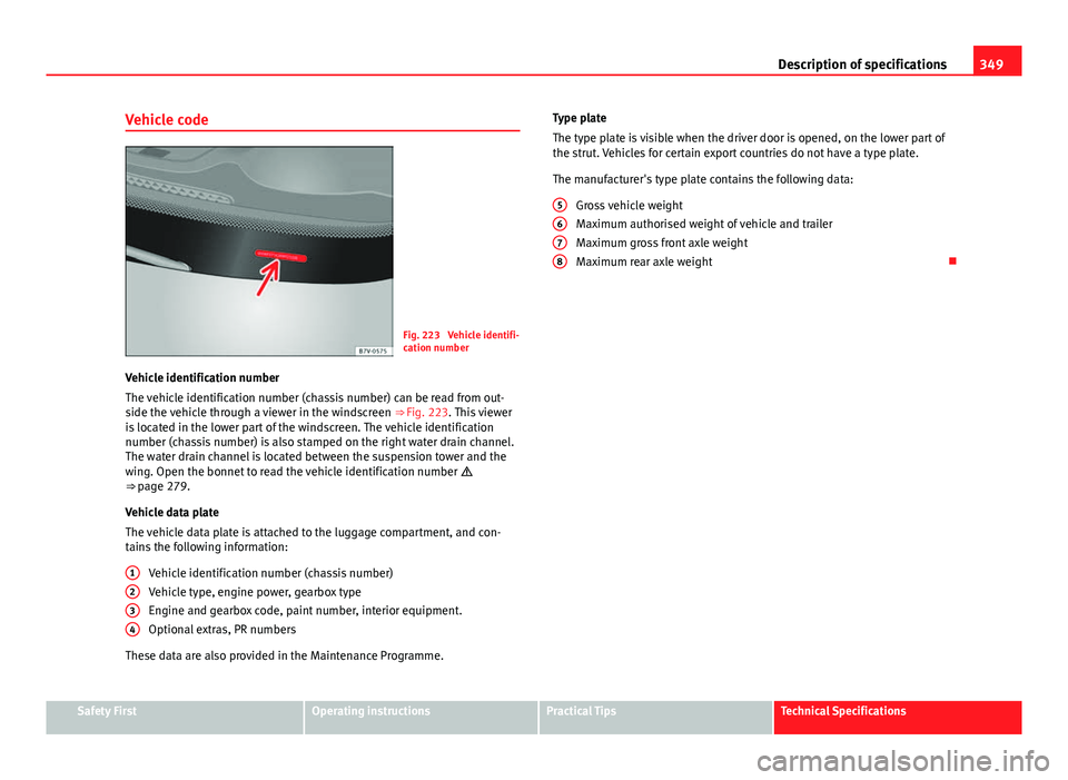
Fig. 223 Vehicle identifi-
cation number
Vehicle identification number
The vehicle identification number (chassis number) can be read from out-
side the vehicle through a viewer in the windscreen ⇒ Fig. 223. This viewer
is located in the lower part of the windscreen. The vehicle identification
number (chassis number) is also stamped on the right water drain channel.
The water drain channel is located between the suspension tower and the
wing. Open the bonnet to read the vehicle identification number
⇒ page 279.
Vehicle data plate
The vehicle data plate is attached to the luggage compartment, and con-
tains the following information:
Vehicle identification number (chassis number)
Vehicle type, engine power, gearbox type
Engine and gearbox code, paint number, interior equipment.
Optional extras, PR numbers
These data are also provided in the Maintenance Programme. 1
234
Type plate
The type plate is visible when the driver door is opened, on the lower part of
the strut. Vehicles for certain export countries do not have a type plate.
The manufacturer's type plate contains the following data:
Gross vehicle weight
Maximum authorised weight of vehicle and trailer
Maximum gross front axle weight
Maximum rear axle weight
5678
Safety FirstOperating instructionsPractical TipsTechnical Specifications