warning Seat Altea 2007 Owner's Manual
[x] Cancel search | Manufacturer: SEAT, Model Year: 2007, Model line: Altea, Model: Seat Altea 2007Pages: 302, PDF Size: 9.17 MB
Page 243 of 302
If and when241
Safety First
Operating instructions
Tips and Maintenance
Te c h n i c a l D a t a
Note
Seek professional assistance if the repair of a tyre puncture is not possible
with the sealing compound.Preparation work
What you must do before changing a wheel.– If you have a flat tyre or puncture, park the vehicle as far away
from the flow of traffic as possible.
–Apply the handbrake firmly.
–Engage the first gear, or put the selector lever to position P for
those vehicles with an automatic gearbox.
– All passengers must leave the vehicle. They should wait in a safe
area (for instance behind the roadside crash barrier).
– Check whether the puncture can be mended using the Tyre Mobility System “General observations and safety advice”.
– Unscrew cap from the valve of the affected wheel.
–Take the tyre repair kit from the luggage compartment.
WARNING
Put the hazard warning lights on and place the warning triangle in position.
This is for your own safety and also warns other road users.
Caution
Take the utmost caution when repairing a flat tyre on a gradient.
Note
Please observe legal requirements when doing so.Repairing the puncture
To repair the puncture, once the preliminary tasks are done,
follow these steps.Apply the sealant
– The instructions for using the sealant correctly are on the pack-
aging.
Inflate the tyres.
– Remove the compressor and hose.
– Tighten the fastening nut onto the tyre valve.
– Connect the compressor power supply to the 12 Volt socket.
– Connect the compressor and chec k the tyre pressure with the
pressure gauge.
Finish the repair
– Remove the compressor hose from the valve.
– Check the cap on the tyre valve.
– Disconnect the compressor from the vehicle mains.
altea_ingles_0706.book Seite 241 Mittwoch, 30. August 2006 3:48 15
Page 245 of 302
If and when243
Safety First
Operating instructions
Tips and Maintenance
Te c h n i c a l D a t a
– Take the plastic clip from inside the fuse cover (at left-hand end
of the dash panel), fit it onto the blown fuse and pull the fuse out.
– Replace the blown fuse (which will have a melted metal strip) with a new fuse of the same ampere rating.
– Carefully fit the fuse cover back on to ensure no water can enter the fuse box.The individual electrical circuits are pr otected by fuses. The fuses are located
behind a cover at the left-hand end of the dash panel and on the left-hand
side of the engine compartment.
The electric windows are protected by circuit breakers. These reset automat-
ically after a few seconds when the overload (caused for example by frozen
windows) has been corrected.
Colour coding of fuses
WARNING
Never “repair” damaged fuses and never replace them with fuses with a
higher rating. Failure to comply could re sult in fire. This could also cause
damage to other parts of the electrical system.
Note
•
If a newly replaced fuse blows again after a short time, the electrical
system must be checked by a qualified workshop as soon as possible.
•
If you replace a fuse with a stronger fuse, you could cause damage to
another location in the electrical system.
•
Always keep some spare fuses in the vehicle. These are available from
SEAT dealers.
Colour
Amperes
light brown 5
red 10
blue 15
yellow 20
natural (white) 25
green 30
orange 40
red 50
white 80
blue100
grey 150
violet 200
Colour
Amperes
altea_ingles_0706.book Seite 243 Mittwoch, 30. August 2006 3:48 15
Page 262 of 302
If and when
260
WARNING
•
Please note the safety warnings referring to working in the engine
compartment ⇒page 208, “Working in the engine compartment”.
•
The battery providing assistance must have the same voltage as the flat
battery (12V) and approximately the same capacity (see imprint on
battery). Failure to comply could result in an explosion.
•
Never use jump leads when one of the batteries is frozen. Danger of
explosion! Even after the battery has thawed, battery acid could leak and
cause chemical burns. If a battery freezes, it should be replaced.
•
Keep sparks, flames and lighted cigarettes away from batteries, danger
of explosion. Failure to comply could result in an explosion.
•
Observe the instructions provided by the manufacturer of the jump
leads.
•
Do not connect the negative cable from the other vehicle directly to the
negative terminal of the flat battery. The gas emitted from the battery could
be ignited by sparks. Danger of explosion.
•
Do not attach the negative cable from the other vehicle to parts of the
fuel system or to the brake line.
•
The non-insulated parts of the battery clamps must not be allowed to
touch. The jump lead atta ched to the positive battery terminal must not
touch metal parts of the vehicle, this can cause a short circuit.
•
Position the leads in such a way that they cannot come into contact
with any moving parts in the engine compartment.
•
Do not bend over the batteries. This could result in chemical burns.Note
The vehicles must not touch each other, otherwise electricity could flow as
soon as the positive terminals are connected.
altea_ingles_0706.book Seite 260 Mittwoch, 30. August 2006 3:48 15
Page 263 of 302
If and when261
Safety First
Operating instructions
Tips and Maintenance
Te c h n i c a l D a t a
Towing and tow-startingTo w - s t a r t i n g
The use of jump leads is preferable to tow-starting.We recommend that you do not tow-start your vehicle. Jump-starting
is preferable ⇒page 258.
However, if your vehicle has to be tow-started:
–Engage the 2
nd or the 3
rd gear.
– Keep the clutch pressed down.
– Switch on the ignition.
– Once both vehicles are mo ving, release the clutch.
– As soon as the engine starts, press the clutch and move the gear lever into neutral. This helps to prevent driving into the towing
vehicle.
WARNING
The risk of accidents is high when tow-starting. The vehicle being towed
can easily collide with the towing vehicle.
Caution
When tow-starting, fuel could enter the catalytic converter and damage it.
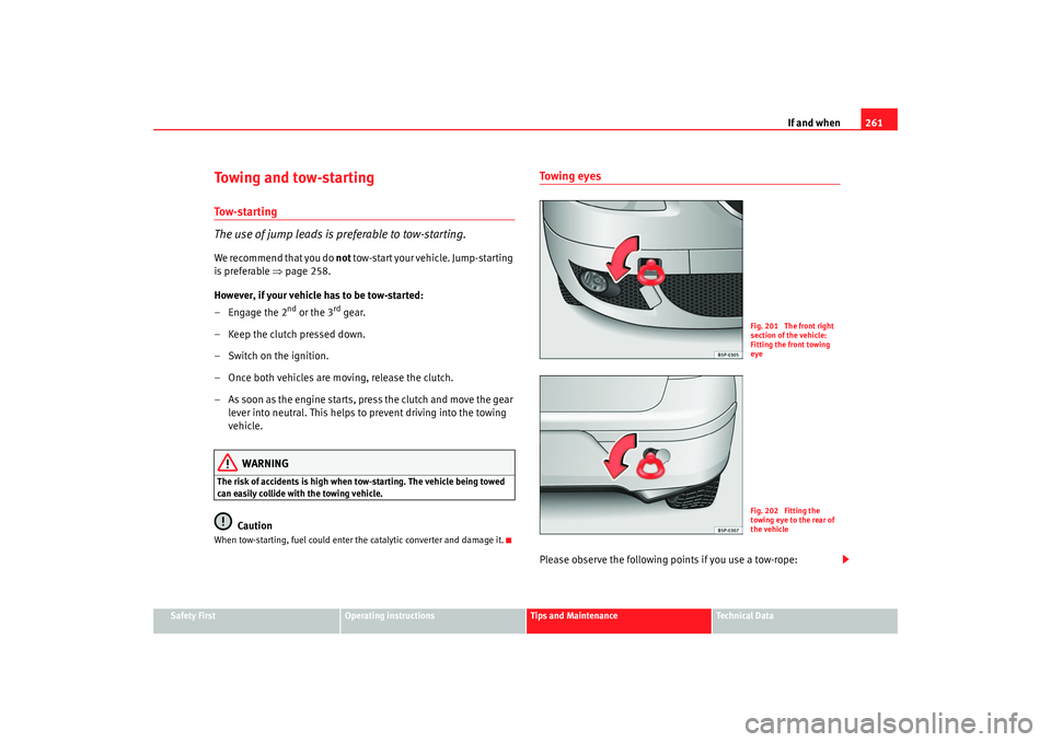
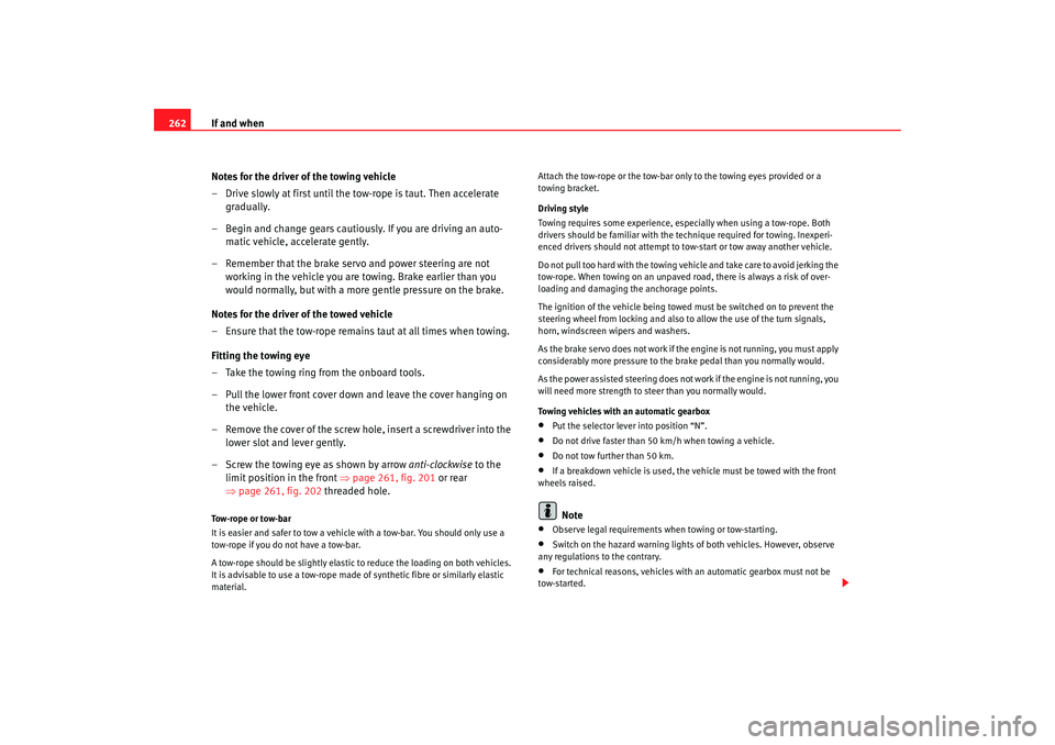
Towing eyesPlease observe the following points if you use a tow-rope:
Fig. 201 The front right
section of the vehicle:
Fitting the front towing
eyeFig. 202 Fitting the
towing eye to the rear of
the vehicle
altea_ingles_0706.book Seite 261 Mittwoch, 30. August 2006 3:48 15
Page 264 of 302
If and when
262
Notes for the driver of the towing vehicle
– Drive slowly at first until the to w-rope is taut. Then accelerate
gradually.
– Begin and change gears cautiously. If you are driving an auto- matic vehicle, accelerate gently.
– Remember that the brake servo and power steering are not working in the vehicle you are towing. Brake earlier than you
would normally, but with a more gentle pressure on the brake.
Notes for the driver of the towed vehicle
– Ensure that the tow-rope remains taut at all times when towing.
Fitting the towing eye
– Take the towing ring from the onboard tools.
– Pull the lower front cover down and leave the cover hanging on the vehicle.
– Remove the cover of the screw hole, insert a screwdriver into the lower slot and lever gently.
– Screw the towing eye as shown by arrow anti-clockwise to the
limit position in the front ⇒page 261, fig. 201 or rear
⇒ page 261, fig. 202 threaded hole.Tow-rope or tow-bar
It is easier and safer to tow a vehicle with a tow-bar. You should only use a
tow-rope if you do not have a tow-bar.
A tow-rope should be slightly elastic to reduce the loading on both vehicles.
It is advisable to use a tow-rope made of synthetic fibre or similarly elastic
material. Attach the tow-rope or the tow-bar only to the towing eyes provided or a
towing bracket.
Driving style
Towing requires some experience, espec
ially when using a tow-rope. Both
drivers should be familiar with the te chnique required for towing. Inexperi-
enced drivers should not attempt to tow-start or tow away another vehicle.
Do not pull too hard with the towing vehicle and take care to avoid jerking the
tow-rope. When towing on an unpaved road, there is always a risk of over-
loading and damaging the anchorage points.
The ignition of the vehicle being towed must be switched on to prevent the
steering wheel from locking and also to allow the use of the turn signals,
horn, windscreen wipers and washers.
As the brake servo does not work if the engine is not running, you must apply
considerably more pressure to the brake pedal than you normally would.
As the power assisted steering does not work if the engine is not running, you
will need more strength to steer than you normally would.
Towing vehicles with an automatic gearbox
•
Put the selector lever into position “N”.
•
Do not drive faster than 50 km/h when towing a vehicle.
•
Do not tow further than 50 km.
•
If a breakdown vehicle is used, the vehicle must be towed with the front
wheels raised.Note
•
Observe legal requirements when towing or tow-starting.
•
Switch on the hazard warning lights of both vehicles. However, observe
any regulations to the contrary.
•
For technical reasons, vehicles with an automatic gearbox must not be
tow-started.
altea_ingles_0706.book Seite 262 Mittwoch, 30. August 2006 3:48 15
Page 265 of 302
If and when263
Safety First
Operating instructions
Tips and Maintenance
Te c h n i c a l D a t a
•
If damage to your vehicle means that there is no lubricant in the gearbox,
you must raise the drive wheels while the vehicle is being towed.
•
If the vehicle has to be towed more than 50 km, the front wheels must be
raised during towing, and towing should be carried out by a qualified person.
•
The steering wheel is locked when the vehicle has no electrical power. The
vehicle must then be towed with the front wheels raised. Towing should be
carried out by a qualified person.
•
The towing eye should always be kept in the vehicle. Please refer to the
notes on ⇒page 261, “Tow-starting”.
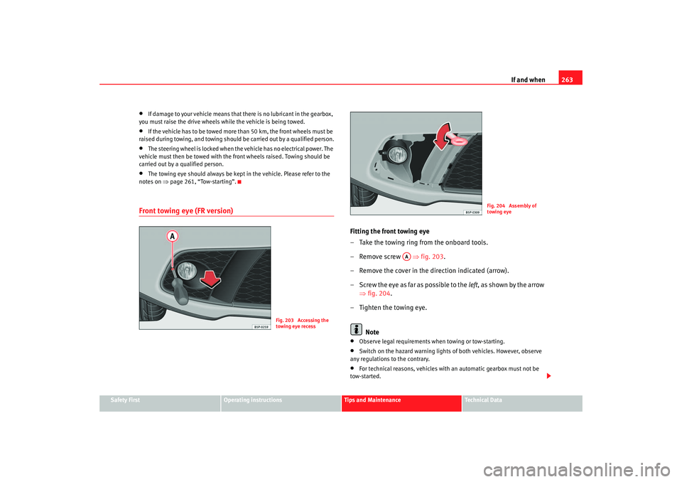
Front towing eye (FR version)
Fitting the front towing eye
– Take the towing ring from the onboard tools.
– Remove screw ⇒fig. 203 .
– Remove the cover in the direction indicated (arrow).
– Screw the eye as far as possible to the left, as shown by the arrow
⇒ fig. 204.
– Tighten the towing eye.
Note•
Observe legal requirements when towing or tow-starting.
•
Switch on the hazard warning lights of both vehicles. However, observe
any regulations to the contrary.
•
For technical reasons, vehicles with an automatic gearbox must not be
tow-started.
Fig. 203 Accessing the
towing eye recess
Fig. 204 Assembly of
towing eye
AA
altea_ingles_0706.book Seite 263 Mittwoch, 30. August 2006 3:48 15
Page 266 of 302
If and when
264•
If damage to your vehicle means that there is no lubricant in the gearbox,
you must raise the drive wheels while the vehicle is being towed.
•
If the vehicle has to be towed more than 50 km, the front wheels must be
raised during towing, and towing should be carried out by a qualified person.
•
The steering wheel is locked when the vehicle has no electrical power. The
vehicle must then be towed with the front wheels raised. Towing should be
carried out by a qualified person.
•
The towing eye should always be kept in the vehicle. Please refer to the
notes on ⇒page 261, “Tow-starting”.
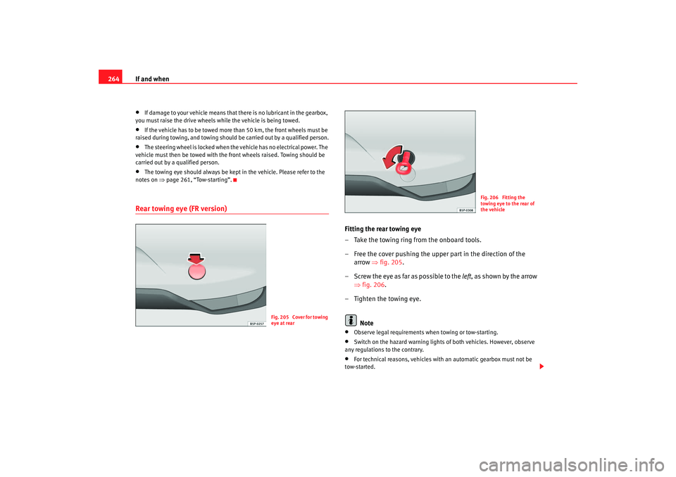
Rear towing eye (FR version)
Fitting the rear towing eye
– Take the towing ring from the onboard tools.
– Free the cover pushing the upper part in the direction of the
arrow ⇒fig. 205.
– Screw the eye as far as possible to the left, as shown by the arrow
⇒ fig. 206.
– Tighten the towing eye.
Note•
Observe legal requirements when towing or tow-starting.
•
Switch on the hazard warning lights of both vehicles. However, observe
any regulations to the contrary.
•
For technical reasons, vehicles with an automatic gearbox must not be
tow-started.
Fig. 205 Cover for towing
eye at rear
Fig. 206 Fitting the
towing eye to the rear of
the vehicle
altea_ingles_0706.book Seite 264 Mittwoch, 30. August 2006 3:48 15
Page 272 of 302
General notes on the technical data
270WeightsKerb weight refers to the basic model with a fuel tank filled to 90% capacity
and without optional extras. The figure quoted includes 75 kg to allow for the
weight of the driver.
For special versions and optional equipment fittings or for the addition of
accessories, the weight of the vehicle will increase ⇒.
WARNING
•
Please note that the centre of gravity may shift when transporting
heavy objects; this may affect the vehi cle's handling and lead to an acci-
dent. Always adjust your speed and dr iving style to suit road conditions
and requirements.
•
Never exceed the gross axle weight rating or the gross vehicle weight
rating. If the allowed axle load or the allowed total weight is exceeded, the
driving characteristics of the vehicle may change, leading to accidents,
injuries and damage to the vehicle.
To w i n g a t r a i l e rTrailer weightsTrailer weights
The trailer weights and drawbar loads approved are selected in intensive
trials according to precisely defined criteria. The approved trailer weights are
valid for vehicles in EU for maximum speeds of 80 km/h (in certain circum-
stances up to 100 km/h). The figures may be different in other countries. All
data in the official vehicle documents take precedence over these data ⇒. Drawbar load
The
maximum permitted weight exerted by the trailer drawbar on the ball joint
of the towing bracket must not exceed 75 kg.
In the interest of road safety, we recommend that you always tow
approaching the maximum drawbar load. The response of the trailer on the
road will be poor if th e drawbar load is too small.
If the maximum permissible drawbar load cannot be met (e.g. with small,
empty and light-weight single axle trailers or tandem axle trailers with an axle
base of less than 1 metre), at least 4% of the actual trailer weight is a legal
stipulation for a drawbar load.
WARNING
•
For safety reasons, you should not drive at speeds above 80 km/h when
towing a trailer. This also applies to countries where higher speeds are
permitted.
•
Never exceed the maximum trailer weights or the draw bar loading. If
the permissible axle load or the perm issible total weight is exceeded, the
driving characteristics of the vehicle may change, leading to accidents,
injuries and damage to the vehicle.
WheelsTyre pressure, snow chains, wheel boltsTyre pressures
The sticker with the tyre pressure values can be found on the inside of the
tank flap. The tyre pressure values given there are for cold tyres. The slightly
raised pressures of warm tyres must not be reduced ⇒.
altea_ingles_0706.book Seite 270 Mittwoch, 30. August 2006 3:48 15
Page 273 of 302
General notes on the technical data 271
Safety First
Operating instructions
Tips and Maintenance
Te c h n i c a l D a t a
Snow chains
Snow chains may be fitted only to the
front wheels.
Consult the chapter “wheels” of this manual.
Wheel bolts
After the wheels have been changed, the tightening torque of the wheel bolts
should be checked as soon as possible with a torque wrench ⇒. The tight-
ening torque for steel and alloy wheels is 120 Nm.
WARNING
•
Check the tyre pressure at least once per month. Correct tyre pressure
is very important. If the tyre pressure is too high or too low, there is an
increased danger of accidents, particularly at high speeds.
•
If the torque of the wheel bolts is too low, they could loosen whilst the
vehicle is in motion. Risk of accident! If the tightening torque is too high,
the wheel bolts and threads could be damaged.Note
We recommend that you ask your Authorised Service Centre for information
about appropriate wheel, tyre and snow chain size.
altea_ingles_0706.book Seite 271 Mittwoch, 30. August 2006 3:48 15
Page 293 of 302
Index291
Index
AABS . . . . . . . . . . . . . . . . . . . . . . . . . . . . . . . . . . . 180
Warning lamp . . . . . . . . . . . . . . . . . . . . . . . . . 78
Accessories . . . . . . . . . . . . . . . . . . . . . . . . . . . . 201
Acoustic signal . . . . . . . . . . . . . . . . . . . . . . . . . . 20
Acoustic warning . . . . . . . . . . . . . . . . . . . . . . . . 161
Adjusting the seat belt height . . . . . . . . . . . . . . 27
Air conditioner* 2C-Climatronic* . . . . . . . . . . . . . . . . . . . . . . 154
Air conditioning system General notes . . . . . . . . . . . . . . . . . . . . . . . . 158
Air conditioning* . . . . . . . . . . . . . . . . . . . . . . . . 151
Air recirculation mode 2C-Climatronic . . . . . . . . . . . . . . . . . . . . . . . 157
Manual air conditioner . . . . . . . . . . . . . . . . 153
Airbag covers . . . . . . . . . . . . . . . . . . . . . . . . . . . . 36
Airbag system . . . . . . . . . . . . . . . . . . . . . . . . . . . 30 Curtain airbags . . . . . . . . . . . . . . . . . . . . . . . 41
Front airbags . . . . . . . . . . . . . . . . . . . . . . . . . 34
Side airbags . . . . . . . . . . . . . . . . . . . . . . . . . . 37
Warning lamp . . . . . . . . . . . . . . . . . . . . . . . . . 31
Airbags Care . . . . . . . . . . . . . . . . . . . . . . . . . . . . . . . . 32
Disposal . . . . . . . . . . . . . . . . . . . . . . . . . . . . . 32
Safety notes . . . . . . . . . . . . . . . . . . . . . . . . . . 32
Alarm system Switching off . . . . . . . . . . . . . . . . . . . . . . . . 102 Alterations to the vehicle . . . . . . . . . . . . . . . . . 201
Alternator
Warning lamp . . . . . . . . . . . . . . . . . . . . . . . . . 79
Ambient temperature display . . . . . . . . . . . . . . . 63
Anti-freeze . . . . . . . . . . . . . . . . . . . . . . . . . . . . . 215
Anti-lock brake system . . . . . . . . . . . . . . . . . . . 180 Warning lamp . . . . . . . . . . . . . . . . . . . . . . . . . 78
Anti-theft alarm system . . . . . . . . . . . . . . . . . . . 102 Switching off . . . . . . . . . . . . . . . . . . . . . . . . 102
Anti-theft wheel bolts . . . . . . . . . . . . . . . . . . . . 236
Apple iPod connector . . . . . . . . . . . . . . . . . . . . 144
Aquaplaning . . . . . . . . . . . . . . . . . . . . . . . . . . . 227
Ashtray* . . . . . . . . . . . . . . . . . . . . . . . . . . . . . . . 142
Automatic anti-dazzle interior mirror* Activating the anti-dazzle function . . . . . . 124
Deactivating anti-dazzle function . . . . . . . . 124
Automatic car washes . . . . . . . . . . . . . . . . . . . . 193
Automatic gearbox / DS G automatic gearbox . 166
Automatic lighting . . . . . . . . . . . . . . . . . . . . . . . 112
Automatic mode 2C-Climatronic . . . . . . . . . . . . . . . . . . . . . . . 155
Automatic wiper/wash function for the rear window . . . . . . . . . . . . . . . . . . . . . . . . . . . 123
Auxiliary audio connection: AUX-IN . . . . . . . . . 143
BBall coupling . . . . . . . . . . . . . . . . . . . . . . . . . . . 189 BAS . . . . . . . . . . . . . . . . . . . . . . . . . . . . . . . . . . . 179
Battery
Changing . . . . . . . . . . . . . . . . . . . . . . . . . . . 224
Charging . . . . . . . . . . . . . . . . . . . . . . . . . . . . 224
Winter conditions . . . . . . . . . . . . . . . . . . . . 223
Belt tension device Disposal . . . . . . . . . . . . . . . . . . . . . . . . . . . . . 28
Warning lamp . . . . . . . . . . . . . . . . . . . . . . . . 31
Belt tension devices . . . . . . . . . . . . . . . . . . . . . . 28
Biodiesel . . . . . . . . . . . . . . . . . . . . . . . . . . . . . . 207
Bonnet . . . . . . . . . . . . . . . . . . . . . . . . . . . . . . . . 210
Brake assist system . . . . . . . . . . . . . . . . . . . . . 179
Brake fluid . . . . . . . . . . . . . . . . . . . . . . . . . . . . . 221 Changing . . . . . . . . . . . . . . . . . . . . . . . . . . . 222
Warning lamp . . . . . . . . . . . . . . . . . . . . . . . . 64
Brake pad wear indicator* Indicator . . . . . . . . . . . . . . . . . . . . . . . . . . . . . 82
Brake pads . . . . . . . . . . . . . . . . . . . . . . . . . . . . . 183
Brake servo . . . . . . . . . . . . . . . . . . . . . . . 179, 183
Brake system . . . . . . . . . . . . . . . . . . . . . . . . . . . 221 Warning lamp . . . . . . . . . . . . . . . . . . . . . . . . 77
Brakes . . . . . . . . . . . . . . . . . . . . . . . . . . . . . . . . 183
Braking distance . . . . . . . . . . . . . . . . . . . . . . . . 183
Bulb changes general notes . . . . . . . . . . . . . . . . . . . . . . . . 249
Bulb defect warning lamp . . . . . . . . . . . . . . . . . . . . . . . . . 76
Buzzer . . . . . . . . . . . . . . . . . . . . . . . . . . . . 116, 161
altea_ingles_0706.book Seite 291 Mittwoch, 30. August 2006 3:48 15