Seat Altea Freetrack 2007 Workshop Manual
Manufacturer: SEAT, Model Year: 2007, Model line: Altea Freetrack, Model: Seat Altea Freetrack 2007Pages: 312, PDF Size: 9.14 MB
Page 51 of 312
Child safety49
Safety First
Operating instructions
Tips and Maintenance
Te c h n i c a l D a t a
Group 1 child seats
A suitable child seat and a correctly adjusted seat belt can
help to protect your child.Child seats using the “ISOFIX” and “Top tether” system (or even the anti-rota-
tion system) or seats in which the chil d faces the rear of the car are most
appropriate for babies and small children weighing between 9 and 18 kg.
Follow the manufacturer's instructions and observe any statutory require-
ments when installing and using child seats.
We recommend that you include the manufacturer's directions for child seat
use in the vehicle wallet and always keep them in the vehicle.
WARNING
Read and always observe information and warnings concerning the use of
child seats ⇒ in “Safety notes on using child seats” on page 47.
Group 2 and 3 child seats
A suitable child seat and a corr ectly adjusted seat belt can
help to protect your child.Follow the manufacturer's instructio ns and observe any statutory require-
ments when installing and using child seats.
We recommend that you include the manufacturer's directions for child seat
use in the vehicle wallet and always keep them in the vehicle.
Group 2 child seats
Children under 7 years of age weighing between 15 and 25 kg are best
protected by group 2 child seats in conjunction with properly adjusted seat
belts.
Group 3 child seats
Children over 7 years of age weighing between 22 and 36 kg but less than 1.5
metres tall are best protected by seat cushions with head restraints in
conjunction with properly worn seat belts ⇒fig. 30.
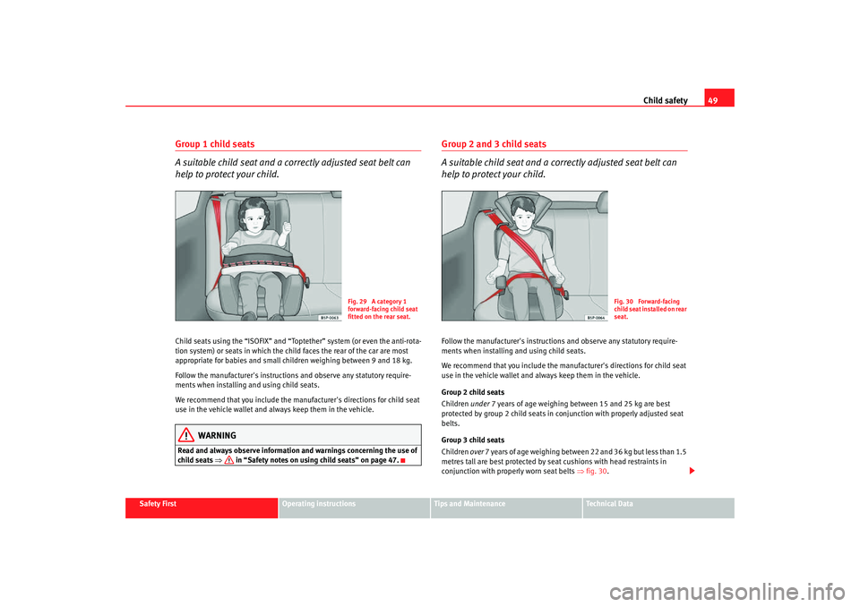
Fig. 29 A category 1
forward-facing child seat
fitted on the rear seat.
Fig. 30 Forward-facing
child seat installed on rear
seat.
altea_xl ingles.book Seite 49 Donnerstag, 12. April 2007 12:56 12
Page 52 of 312

Child safety
50
WARNING
•
The shoulder part of th e seat belt must lie approximately on the centre
of the shoulder, never across the neck or the arm. The seat belt must lie
close to the torso. The lap belt part must lie across the pelvis, not across
the stomach, and always fit closely. Pull the belt tight if necessary to take
up any slack ⇒page 24, “Seat belts”.
•
Read and always observe information and warnings concerning the use
of child seats ⇒ in “Safety notes on using child seats” on page 47.
altea_xl ingles.book Seite 50 Donnerstag, 12. April 2007 12:56 12
Page 53 of 312

Child safety51
Safety First
Operating instructions
Tips and Maintenance
Te c h n i c a l D a t a
Securing child seatsWays to secure a child seat
A child seat can be secured differently on th e rear seat and on the front passenger seat.You can secure a child seat to the rear seat or front passenger seat in the
following ways:•
Child seats in groups 0 to 3 can be secured with a seat belt.
•
Child seats from the groups 0, 0+ and 1 using the “ISOFIX” and
“Toptether” systems or the antirotation system may be secured without using
the adult seatbelt and using the “ISOFIX” and “Toptether” anchors or the anti-
rotation mechanism/brackets.
U: Suitable for universal approved rest raining systems for use in this age
category (universal retention systems are those fitted using the adult
seat belt.
*: Move the passenger seat as far to rear as possible, as high as possible and always deactivate the airbag.
L: Suitable for retention systems us ing the “ISOFIX” and “Toptether”
anchors or antirotation mechanism/bracket
WARNING
•
When travelling, children must be secured in the vehicle with a
restraint system suitable for age, weight and size.
•
Never install a child seat facing backwards (or rear-facing) on the front
passenger seat unless the front passenger airbag has been disabled. This
represents a risk of fatal injuries to the child! However, if a child must,
under exceptional circumstances, travel in the front passenger seat, the
passenger airbag must be deactivated ⇒page 44, “Deactivating airbags*”
and the seat put into the highest position where possible.
•
Read and always observe information and warnings concerning the use
of child seats ⇒ in “Safety notes on using child seats” on page 47.
Weight class
Weight Seat locations
Front passenger Rear outerRear centre
Group 0 <10 kgU*U/L U
Group 0+ <13 kgU*U/L U
Group 1 9-18 kgU*U/L U
Group 2 / 3 15-36 kgU*UUWARNING (continued)
altea_xl ingles.book Seite 51 Donnerstag, 12. April 2007 12:56 12
Page 54 of 312

Child safety
52Securing the child seat using the “ISOFIX” and “Toptether” system or the antirotation mechanism/system.
The child seat with “ISOFIX” system can be secured quickly,
easily and safely on the rear outer seats using the systemWhen removing or fitting the child seat, please be sure to follow the
manufacturer's instructions.
– Move the seat as far to rear as it will go.
– Press the child seat onto the “ISOFIX” retaining rings until the
child seat can be heard to engage securely. If the child seat is
fitted with “Toptether” anchoring, connect it to the corre-
sponding ring. If the child seat is fitted with any other antirota-
tion system, follow the manufacturer instructions carefully.
– Pull on both sides of the child se at to ensure that it is secure.
Two “ISOFIX” retaining rings are fitted on each rear seat. In some vehicles, the
rings are secured to the seat frame and in others they are secured to the rear
floor. The “ISOFIX” rings can be accessed between the seat back and the seat
cushion. The “Toptether” rings are located in the rear space in the back. They
are often located on the rear of the seat backs.
Child seats with “ISOFIX” and “Topteth er” mountings are available from the
Authorised Service Centres.
WARNING
•
The retaining rings are designed only for use with “ISOFIX” and
“Toptether” systems.
•
Never secure child seats that do not have the “ISOFIX” or “Toptether”
system, retaining belts or objects to the fastening rings – this can result in
potentially fatal injuries to the child!
•
Ensure that the child seat is secu red correctly using the “ISOFIX” and
“Toptether” anchors.
Fig. 31 ISOFIX securing
rings
altea_xl ingles.book Seite 52 Donnerstag, 12. April 2007 12:56 12
Page 55 of 312
53
Safety First
Operating instructions
Tips and Maintenance
Te c h n i c a l D a t a
altea_xl ingles.book Seite 53 Donnerstag, 12. April 2007 12:56 12
Page 56 of 312

54
Fig. 32 Instrument panelaltea_xl ingles.book Seite 54 Donnerstag, 12. April 2007 12:56 12
Page 57 of 312
Cockpit55
Safety First
Operating instructions
Tips and Maintenance
Te c h n i c a l D a t a
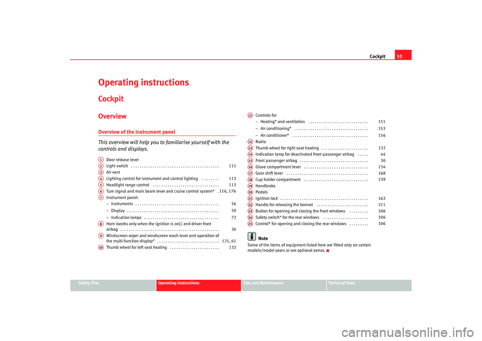
Operating instructionsCockpitOverviewOverview of the instrument panel
This overview will help you to familiarise yourself with the
controls and displays.
Door release lever
Light switch . . . . . . . . . . . . . . . . . . . . . . . . . . . . . . . . . . . . . . . . .
Air vent
Lighting control for instrument and control lighting . . . . . . . .
Headlight range control . . . . . . . . . . . . . . . . . . . . . . . . . . . . . . .
Turn signal and main beam lever and cruise control system* .
Instrument panel:
− Instruments . . . . . . . . . . . . . . . . . . . . . . . . . . . . . . . . . . . . . . .
− Display . . . . . . . . . . . . . . . . . . . . . . . . . . . . . . . . . . . . . . . . . . .
− Indication lamps . . . . . . . . . . . . . . . . . . . . . . . . . . . . . . . . . . .
Horn (works only when the igni tion is on)/ and driver front
airbag . . . . . . . . . . . . . . . . . . . . . . . . . . . . . . . . . . . . . . . . . . . . . .
Windscreen wiper and windscreen wash lever and operation of
the multi-function display* . . . . . . . . . . . . . . . . . . . . . . . . . . . . .
Thumb wheel for left seat heating . . . . . . . . . . . . . . . . . . . . . . . Controls for
−
Heating* and ventilation . . . . . . . . . . . . . . . . . . . . . . . . . . . .
− Air conditioning* . . . . . . . . . . . . . . . . . . . . . . . . . . . . . . . . . .
− Air conditioner* . . . . . . . . . . . . . . . . . . . . . . . . . . . . . . . . . . .
Radio
Thumb wheel for right seat heating . . . . . . . . . . . . . . . . . . . . . .
Indication lamp for deactivated front passenger airbag . . . . .
Front passenger airbag . . . . . . . . . . . . . . . . . . . . . . . . . . . . . . . .
Glove compartment lever . . . . . . . . . . . . . . . . . . . . . . . . . . . . . .
Gear shift lever . . . . . . . . . . . . . . . . . . . . . . . . . . . . . . . . . . . . . .
Cup holder compartment . . . . . . . . . . . . . . . . . . . . . . . . . . . . . .
Handbrake
Pedals
Ignition lock . . . . . . . . . . . . . . . . . . . . . . . . . . . . . . . . . . . . . . . . .
Handle for releasing the bonnet . . . . . . . . . . . . . . . . . . . . . . . .
Button for opening and closing the front windows . . . . . . . . .
Safety switch* for the rear windows . . . . . . . . . . . . . . . . . . . . .
Control* for opening and closing the rear windows . . . . . . . . .
Note
Some of the items of equipment listed here are fitted only on certain
models/model years or are optional extras.
A1A2
111
A3A4
113
A5
113
A6
116, 176
A7
56
59
72
A8
30
A9
121, 61
A10
132
A11
151
153
156
A12A13
132
A14
44
A15
30
A16
134
A17
168
A18
139
A19A20A21
163
A22
211
A23
106
A24
106
A25
106
altea_xl ingles.book Seite 55 Donnerstag, 12. April 2007 12:56 12
Page 58 of 312
Cockpit
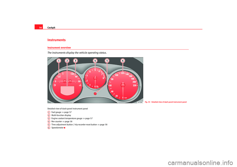
56InstrumentsInstrument overview
The instruments display the vehicle operating status.Detailed view of dash panel instrument panel
Fuel gauge ⇒ page 57
Multi-function display
Engine coolant temperature gauge ⇒page 57
Rev counter ⇒ page 58
Time adjustment button / tr ip recorder reset button ⇒page 58
Speedometer
Fig. 33 Detailed view of dash panel instrument panel
A1A2A3A4A5A6
altea_xl ingles.book Seite 56 Donnerstag, 12. April 2007 12:56 12
Page 59 of 312
Cockpit57
Safety First
Operating instructions
Tips and Maintenance
Te c h n i c a l D a t a
Fuel gauge
and reserve indicator
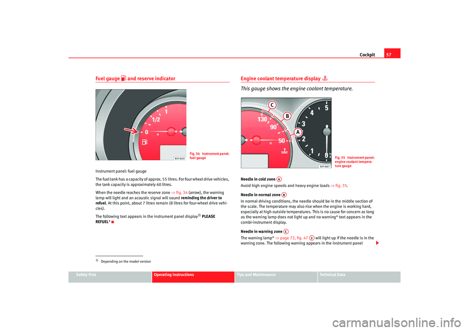
Instrument panel: fuel gauge
The fuel tank has a capacity of approx. 55 litres. For four wheel drive vehicles,
the tank capacity is approximately 60 litres.
When the needle reaches the reserve zone ⇒fig. 34 (arrow), the warning
lamp will light and an acoustic signal will sound reminding the driver to
refuel . At this point, about 7 litres remain (8 litres for four-wheel drive vehi-
cles).
The following text appears in the instrument panel display
3) PLEASE
REFUEL *
Engine coolant temperature display
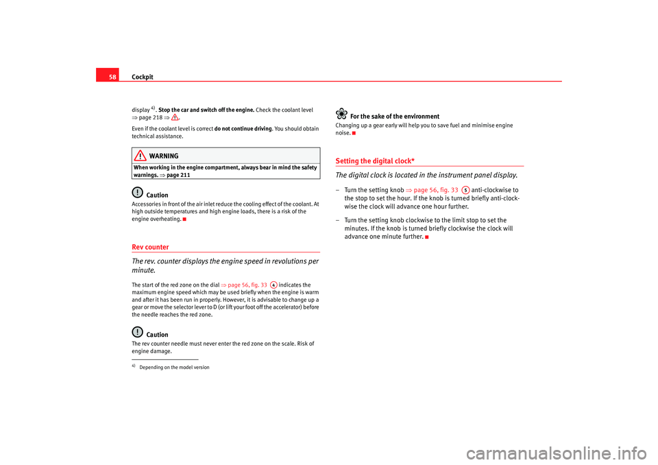
This gauge shows the engine coolant temperature.
Needle in cold zone
Avoid high engine speeds and heavy engine loads ⇒fig. 35.
Needle in normal zone
In normal driving conditions, the needle should be in the middle section of
the scale. The temperature may also rise when the engine is working hard,
especially at high outside temperatures. This is no cause for concern as long
as the warning lamp does not light up and no warning* text appears in the
combi-instrument display.
Needle in warning zone
The warning lamp* ⇒page 72, fig. 47 will light up if the needle is in the
warning zone. The following warning ap pears in the instrument panel
3)Depending on the model version
Fig. 34 Instrument panel:
fuel gauge
Fig. 35 Instrument panel:
engine coolant tempera-
ture gauge
AAABAC
A2
altea_xl ingles.book Seite 57 Donnerstag, 12. April 2007 12:56 12
Page 60 of 312
Cockpit
58display
4). Stop the car and switch off the engine. Check the coolant level
⇒ page 218 ⇒.
Even if the coolant level is correct do not continue driving. You should obtain
technical assistance.WARNING
When working in the engine compartment, always bear in mind the safety
warnings. ⇒page 211
Caution
Accessories in front of the air inlet reduce the cooling effect of the coolant. At
high outside temperatures and high engine loads, there is a risk of the
engine overheating.Rev counter
The rev. counter displays the engine speed in revolutions per
minute.The start of the red zone on the dial ⇒page 56, fig. 33 indicates the
maximum engine speed which may be used briefly when the engine is warm
and after it has been run in properly. However, it is advisable to change up a
gear or move the selector lever to D (or l ift your foot off the accelerator) before
the needle reaches the red zone.
Caution
The rev counter needle must never enter the red zone on the scale. Risk of
engine damage.
For the sake of the environment
Changing up a gear early will help you to save fuel and minimise engine
noise.Setting the digital clock*
The digital clock is located in the instrument panel display.– Turn the setting knob ⇒page 56, fig. 33 anti-clockwise to
the stop to set the hour. If the kn ob is turned briefly anti-clock-
wise the clock will advance one hour further.
– Turn the setting knob clockwise to the limit stop to set the minutes. If the knob is turned briefly clockwise the clock will
advance one minute further.
4)Depending on the model version
A4
A5
altea_xl ingles.book Seite 58 Donnerstag, 12. April 2007 12:56 12