Seat Altea XL 2010 Owner's Manual
Manufacturer: SEAT, Model Year: 2010, Model line: Altea XL, Model: Seat Altea XL 2010Pages: 312, PDF Size: 8.41 MB
Page 151 of 312
Seats and stowage149
Safety First
Operating instructions
Practical tips
Technical Data
Electrical sockets
Electrical equipment can be connected to any of the 12 volt
sockets.
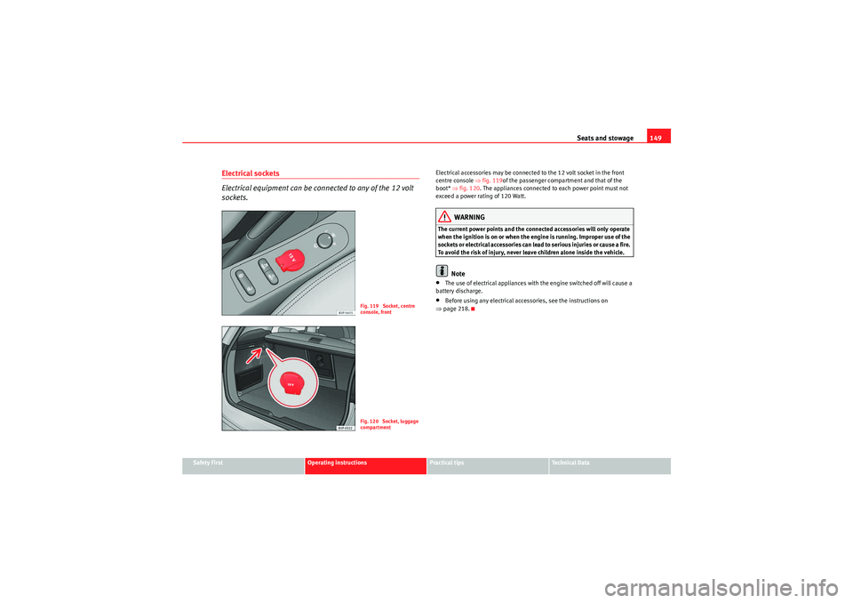
Electrical accessories may be connected to the 12 volt socket in the front
centre console ⇒fig. 119 of the passenger compartment and that of the
boot* ⇒fig. 120 . The appliances connected to each power point must not
exceed a power rating of 120 Watt.
WARNING
The current power points and the connected accessories will only operate
when the ignition is on or when the engine is running. Improper use of the
sockets or electrical accessories can lead to serious injuries or cause a fire.
To avoid the risk of injury, never leave children alone inside the vehicle.
Note
•The use of electrical appliances with the engine switched off will cause a
battery discharge.•Before using any electrical accessories, see the instructions on
⇒ page 218.
Fig. 119 Socket, centre
console, frontFig. 120 Socket, luggage
compartment
AlteaXL_EN.book Seite 149 Dienstag, 1. September 2009 10:37 10
Page 152 of 312
Seats and stowage
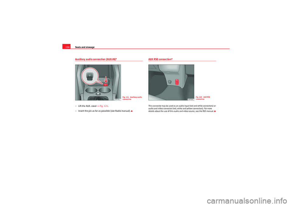
150Auxiliary audio connection (AUX-IN)*– Lift the AUX. cover ⇒fig. 121 .
– Insert the pin as far as possible (see Radio manual).
AUX RSE connection*This connector may be used as an audio input (red and white connectors) or
audio and video connector (red, white and yellow connectors). For more
details about the use of this audio and video source, see the RSE manual.
Fig. 121 Auxiliary audio
connection
Fig. 122 AUX RSE
connection
AlteaXL_EN.book Seite 150 Dienstag, 1. September 2009 10:37 10
Page 153 of 312
Seats and stowage151
Safety First
Operating instructions
Practical tips
Technical Data
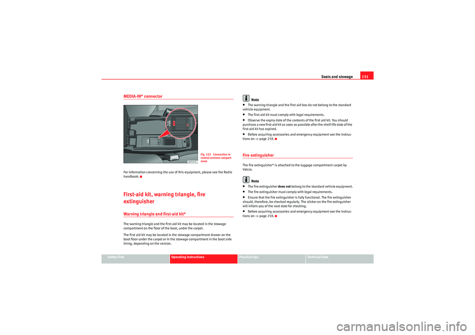
MEDIA-IN* connectorFor information concerning the use of this equipment, please see the Radio
handbook.First-aid kit, warning triangle, fire
extinguisherWarning triangle and first-aid kit*The warning triangle and the first aid kit may be located in the stowage
compartment on the floor of the boot, under the carpet.
The first aid kit may be located in the stowage compartment drawer on the
boot floor under the carpet or in the stowage compartment in the boot side
lining, depending on the version.
Note
•The warning triangle and the first aid box do not belong to the standard
vehicle equipment.•The first aid kit must comply with legal requirements.•Observe the expiry date of the contents of the first aid kit. You should
purchase a new first-aid kit as soon as possible after the shelf-life date of the
first-aid kit has expired.•Before acquiring accessories and emergency equipment see the instruc-
tions on ⇒page 218.Fire extinguisherThe fire extinguisher* is attached to the luggage compartment carpet by
Vel cro.
Note
•The fire extinguisher does not belong to the standard vehicle equipment.•The fire extinguisher must comply with legal requirements.•Ensure that the fire extinguisher is fully functional. The fire extinguisher
should, therefore, be checked regularly. The sticker on the fire extinguisher
will inform you of the next date for checking.•Before acquiring accessories and emergency equipment see the instruc-
tions on ⇒page 218.
Fig. 123 Connection in
central armrest compart-
ment
AlteaXL_EN.book Seite 151 Dienstag, 1. September 2009 10:37 10
Page 154 of 312
Seats and stowage
152Luggage compartmentStowing luggage
All luggage must be securely stowed.Please observe the following points to ensure the vehicle handles
well at all times:
– Distribute the load as evenly as possible.
– Place heavy objects as far forward in the luggage compartment
as possible.
– Secure luggage in the luggage compartment with suitable straps on the fastening rings*.
WARNING
•Loose luggage and other loose items in the vehicle can cause serious
injuries.•Loose objects in the luggage compartment can suddenly move and
change the way the vehicle handles.•During sudden manoeuvres or accidents, loose objects in the
passenger compartment can be flung forward, injuring vehicle occupants.•Always store objects in the luggage compartment and secure with suit-
able straps. This is especially important for heavy objects.•When you transport heavy objects, always take in account that a
change in the centre of gravity can also cause changes in vehicle handling.•Please observe information on safe driving ⇒page 7, “Safe driving”.
Caution
Hard objects on the shelf could chafe against the wires of the heating
element in the rear window and cause damage.
Note
The ventilation slots in front of the rear side windows must not be covered as
this would prevent stale air being extracted from the vehicle.
AlteaXL_EN.book Seite 152 Dienstag, 1. September 2009 10:37 10
Page 155 of 312
Seats and stowage153
Safety First
Operating instructions
Practical tips
Technical Data
Luggage compartment cover
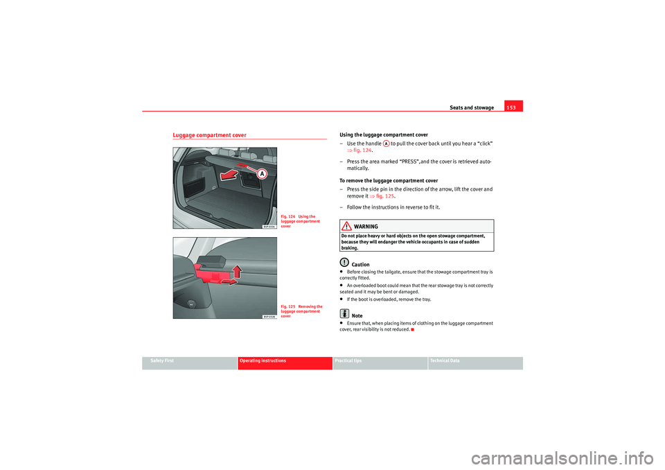
Using the luggage compartment cover
– Use the handle to pull the cover back until you hear a “click”
⇒fig. 124 .
– Press the area marked “PRESS”,and the cover is retrieved auto- matically.
To remove the luggage compartment cover
– Press the side pin in the direction of the arrow, lift the cover and remove it ⇒fig. 125 .
– Follow the instructions in reverse to fit it.
WARNING
Do not place heavy or hard objects on the open stowage compartment,
because they will endanger the vehicle occupants in case of sudden
braking.
Caution
•Before closing the tailgate, ensure that the stowage compartment tray is
correctly fitted.•An overloaded boot could mean that the rear stowage tray is not correctly
seated and it may be bent or damaged.•If the boot is overloaded, remove the tray.Note
•Ensure that, when placing items of clothing on the luggage compartment
cover, rear visibility is not reduced.
Fig. 124 Using the
luggage compartment
coverFig. 125 Removing the
luggage compartment
cover
AA
AlteaXL_EN.book Seite 153 Dienstag, 1. September 2009 10:37 10
Page 156 of 312
Seats and stowage
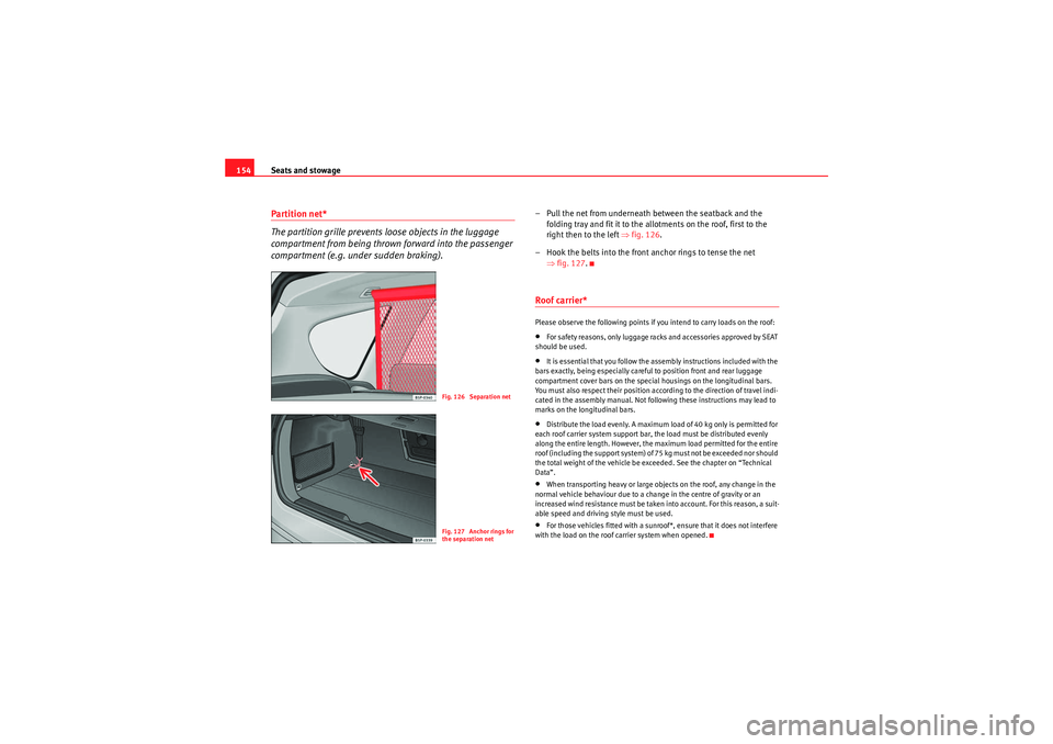
154Partition net*
The partition grille prevents loose objects in the luggage
compartment from being thrown forward into the passenger
compartment (e.g. under sudden braking).
– Pull the net from underneath between the seatback and the
folding tray and fit it to the allotments on the roof, first to the
right then to the left ⇒ fig. 126.
– Hook the belts into the front anchor rings to tense the net ⇒fig. 127 .Roof carrier*Please observe the following points if you intend to carry loads on the roof:•For safety reasons, only luggage racks and accessories approved by SEAT
should be used.•It is essential that you follow the assembly instructions included with the
bars exactly, being especially careful to position front and rear luggage
compartment cover bars on the special housings on the longitudinal bars.
You must also respect their position according to the direction of travel indi-
cated in the assembly manual. Not following these instructions may lead to
marks on the longitudinal bars.•Distribute the load evenly. A maximum load of 40 kg only is permitted for
each roof carrier system support bar, the load must be distributed evenly
along the entire length. However, the maximum load permitted for the entire
roof (including the support system) of 75 kg must not be exceeded nor should
the total weight of the vehicle be exceeded. See the chapter on “Technical
Data”.•When transporting heavy or large objects on the roof, any change in the
normal vehicle behaviour due to a change in the centre of gravity or an
increased wind resistance must be taken into account. For this reason, a suit-
able speed and driving style must be used.•For those vehicles fitted with a sunroof*, ensure that it does not interfere
with the load on the roof carrier system when opened.
Fig. 126 Separation netFig. 127 Anchor rings for
the separation net
AlteaXL_EN.book Seite 154 Dienstag, 1. September 2009 10:37 10
Page 157 of 312
Heating, Ventilation and Air conditioning155
Safety First
Operating instructions
Practical tips
Technical Data
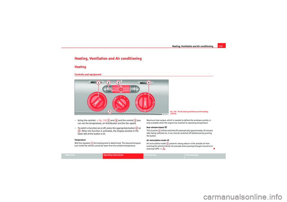
Heating, Ventilation and Air conditioningHeatingControls and equipment– Using the controls ⇒fig. 128 and and the control you
can set the temperature, air distribution and the fan speed.
– To switch a function on or off, press the appropriate button or . When the function is activated, the display window in the
lower left of the button is lit.Te m p e r a t u r e
With the regulator the heating level is determined. The required tempera-
ture inside the vehicle cannot be lower than the ambient temperature. Maximum heat output, which is needed to defrost the windows quickly, is
only available when the engine has reached its operating temperature.
Rear window heater
This function will be switched off automatically approximately
20 minutes
after being switched on. It can also be switched off beforehand by pushing
the button
Air recirculation mode
Air recirculation mode prevents strong odours in the outside air from
entering the vehicle interior, for example when passing through a tunnel or in
queuing traffic ⇒.
Fig. 128 On the dash panel there are the heating
controls
A1
A4
A5A2
A3
A1
A2
A3
AlteaXL_EN.book Seite 155 Dienstag, 1. September 2009 10:37 10
Page 158 of 312
Heating, Ventilation and Air conditioning
156With low temperatures outside, the air recirculation increases the effective-
ness of the heating system by heating the air inside the passenger compart-
ment rather than the air from outside.
Air distribution
Control for setting the flow of air in the required direction. – Air distribution towards the windscreen. If the windscreen air output is
on and the air recirculation mode is pressed, this remains active. When the
recirculation mode is on, if the air distribution towards the windscreen mode
is selected, the recirculation mode is deactivated. For safety reasons, the air
recirculation mode should not be connected. – Air distribution to the upper body. – Air distribution to footwell – Air distribution to the windscreen and the foot well.
Blower
The air flow can be set at four speeds with the control . The air flow should
always be set at the lowest speed when driving slowly.
WARNING
•For road safety all windows must be clear of ice, snow, and condensa-
tion. This is essential to ensure good visibility. Please familiarise yourself
with the correct operation of the heating and ventilation system, including
the anti-fog/defrost functions for the windscreens.•In air recirculation mode, no cold air from the outside enters the vehicle
interior. The windows can quickly fog over if the heating is switched off.
Therefore, never leave the air recirculation mode switched on for a long
time (risk of accident).Note
Please observe the general notes ⇒page 165.
A4
A5
AlteaXL_EN.book Seite 156 Dienstag, 1. September 2009 10:37 10
Page 159 of 312
Heating, Ventilation and Air conditioning157
Safety First
Operating instructions
Practical tips
Technical Data
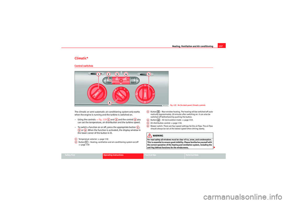
Climatic*Control switchesThe climatic or semi-automatic air conditioning system only works
when the engine is running and the turbine is switched on.
– Using the controls ⇒fig. 129 and and the control you
can set the temperature, air distribution and the turbine speed.
– To switch a function on or off, press the appropriate button , or . When the function is activated, the display window in
the lower corner of the button is lit.
Temperature selector ⇒page 158
Button – Heating, ventilation and air-conditioning system on/off
⇒ page 158 Button – Rear window heating. The heating will be switched off auto-
matically approximately
20 minutes after switching on. It can also be
switched off beforehand by pushing the button.
Button – Air recirculation mode ⇒page 159.
Air distribution control ⇒page 158.
Blower switch. There are four speed settings for the air flow. The air flow
should always be set at the lowest speed when driving slowly.
WARNING
For road safety all windows must be clear of ice, snow, and condensation.
This is essential to ensure good visibility. Please familiarise yourself with
the correct operation of the heating and ventilation system, including the
anti-fog/defrost functions for the windscreens.
Fig. 129 On the dash panel: Climatic controls
A1
A5
A6A2
A3
A4
A1A2
AC
A3
A4
A5A6
AlteaXL_EN.book Seite 157 Dienstag, 1. September 2009 10:37 10
Page 160 of 312
Heating, Ventilation and Air conditioning
158
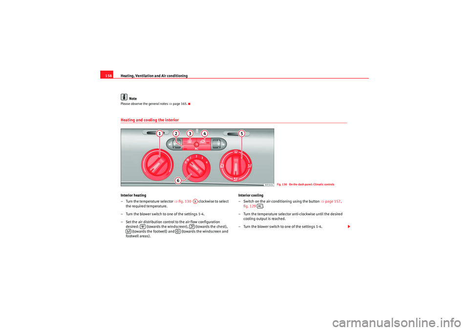
NotePlease observe the general notes ⇒page 165.Heating and cooling the interiorInterior heating
– Turn the temperature selector ⇒fig. 130 clockwise to select
the required temperature.
– Turn the blower switch to one of the settings 1-4.
– Set the air distribution control to the air flow configuration desired: (towards the windscreen), (towards the chest), (towards the footwell) and (towards the windscreen and
footwell areas). Interior cooling
– Switch on the air conditioning using the button
⇒page 157,
fig. 129 .
– Turn the temperature selector anti-clockwise until the desired cooling output is reached.
– Turn the blower switch to one of the settings 1-4.
Fig. 130 On the dash panel: Climatic controls
A1
AC
AlteaXL_EN.book Seite 158 Dienstag, 1. September 2009 10:37 10