headlight Seat Altea XL 2012 User Guide
[x] Cancel search | Manufacturer: SEAT, Model Year: 2012, Model line: Altea XL, Model: Seat Altea XL 2012Pages: 315, PDF Size: 4.51 MB
Page 132 of 315
130Lights and visibility
Rear window wiper
The windscreen wiper lever operates the windscreen wiper
and the wash and wipe system for the rear window.
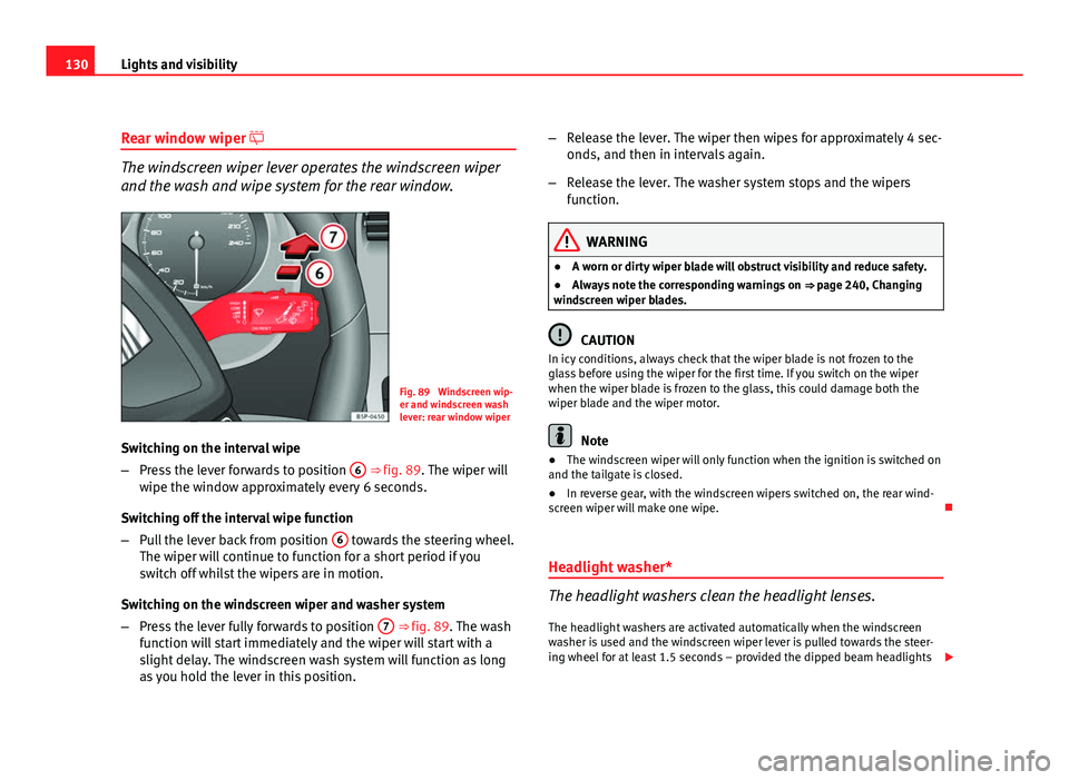
Fig. 89 Windscreen wip-
er and windscreen wash
lever: rear window wiper
Switching on the interval wipe
– Press the lever forwards to position 6
⇒ fig. 89. The wiper will
wipe the window approximately every 6 seconds.
Switching off the interval wipe function
– Pull the lever back from position 6
towards the steering wheel.
The wiper will continue to function for a short period if you
switch off whilst the wipers are in motion.
Switching on the windscreen wiper and washer system
– Press the lever fully forwards to position 7
⇒ fig. 89. The wash
function will start immediately and the wiper will start with a
slight delay. The windscreen wash system will function as long
as you hold the lever in this position. –
Release the lever. The wiper then wipes for approximately 4 sec-
onds, and then in intervals again.
– Release the lever. The washer system stops and the wipers
function.
WARNING
● A worn or dirty wiper blade will obstruct visibility and reduce safety.
● Always note the corresponding warnings on ⇒ page 240, Changing
windscreen wiper blades.
CAUTION
In icy conditions, always check that the wiper blade is not frozen to the
glass before using the wiper for the first time. If you switch on the wiper
when the wiper blade is frozen to the glass, this could damage both the
wiper blade and the wiper motor.
Note
● The windscreen wiper will only function when the ignition is switched on
and the tailgate is closed.
● In reverse gear, with the windscreen wipers switched on, the rear wind-
screen wiper will make one wipe.
Headlight washer*
The headlight washers clean the headlight lenses. The headlight washers are activated automatically when the windscreen
washer is used and the windscreen wiper lever is pulled towards the steer-
ing wheel for at least 1.5 seconds – provided the dipped beam headlights
Page 133 of 315
131
Lights and visibility
or main beams are switched on. Clean off stubborn dirt (insects, etc.) from
the headlights at regular intervals, for instance when filling the fuel tank.
Note
● To ensure that the headlight washers work properly in winter, keep the
nozzle holders in the bumper free of snow and remove any ice with a de-icer
spray.
● To remove water, the windscreen wipers will be activated from time to
time, the headlight wipers will be activated every three cycles.
Rear-view mirrors Interior mirror
It is dangerous to drive if you cannot see clearly through the
rear window.Manual anti-dazzle function for interior mirror
In the basic mirror position, the lever at the bottom edge of the mirror
should be at the front. Pull the lever to the back to select the anti-dazzle
function. Automatic anti-dazzle interior mirror*
The automatic anti-dazzle function can be switched on and
off as desired.
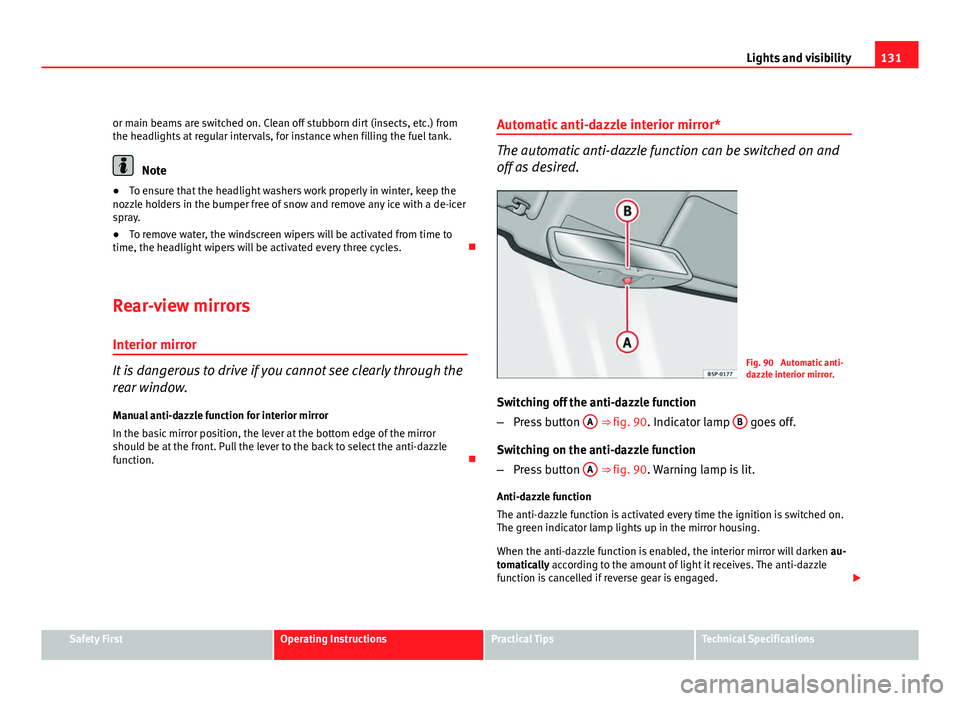
Fig. 90 Automatic anti-
dazzle interior mirror.
Switching off the anti-dazzle function
– Press button A
⇒ fig. 90. Indicator lamp B goes off.
Switching on the anti-dazzle function
– Press button A
⇒ fig. 90. Warning lamp is lit.
Anti-dazzle function
The anti-dazzle function is activated every time the ignition is switched on.
The green indicator lamp lights up in the mirror housing.
When the anti-dazzle function is enabled, the interior mirror will darken au-
tomatically according to the amount of light it receives. The anti-dazzle
function is cancelled if reverse gear is engaged.
Safety FirstOperating InstructionsPractical TipsTechnical Specifications
Page 192 of 315
190Driving
Cruise speed* (Cruise control system)
Description
The cruise control system is able to maintain the set speed
in the range of 30 km/h to 180 km/h.
Once the speed setting has been saved, you may take your foot off the ac-
celerator.
WARNING
It could be dangerous to use the cruise control system if it is not possible
to drive at constant speed.
● Do not use the cruise control system when driving in dense traffic, on
roads with lots of bends or on roads with poor conditions (with ice, slip-
pery surfaces, loose grit or gravel), as this could cause an accident.
● Always switch the cruise control system off after using it in order to
avoid an involuntary use.
● It is dangerous to use a set speed which is too high for the current
road, traffic or weather conditions. Risk of accident.
Note
The cruise control cannot maintain a constant speed when descending
downhill. The vehicle will accelerate due to its own weight. Use the foot
brake to slow the vehicle. Switching the cruise control system on and off
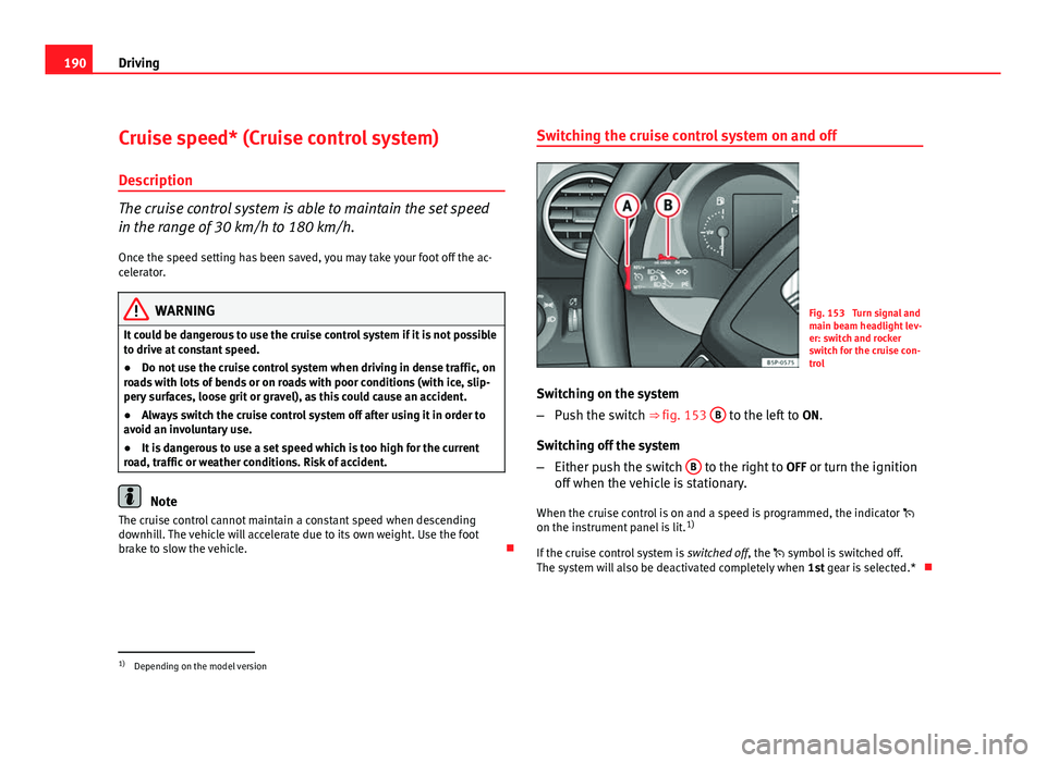
Fig. 153 Turn signal and
main beam headlight lev-
er: switch and rocker
switch for the cruise con-
trol
Switching on the system
– Push the switch ⇒ fig. 153 B
to the left to
ON.
Switching off the system
– Either push the switch B
to the right to
OFF or turn the ignition
off when the vehicle is stationary.
When the cruise control is on and a speed is programmed, the indicator
on the instrument panel is lit. 1)
If the cruise control system is switched off, the symbol is switched off.
The system will also be deactivated completely when 1st gear is selected.*
1)
Depending on the model version
Page 193 of 315
191
Driving
Setting speed*
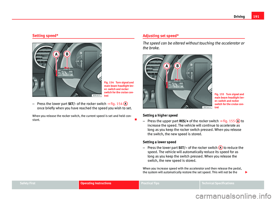
Fig. 154 Turn signal and
main beam headlight lev-
er: switch and rocker
switch for the cruise con-
trol
– Press the lower part SET/- of the rocker switch ⇒ fig. 154 A
once briefly when you have reached the speed you wish to set.
When you release the rocker switch, the current speed is set and held con-
stant. Adjusting set speed*
The speed can be altered without touching the accelerator or
the brake.
Fig. 155 Turn signal and
main beam headlight lev-
er: switch and rocker
switch for the cruise con-
trol
Setting a higher speed
– Press the upper part RES/+ of the rocker switch ⇒ fig. 155 A
to
increase the speed. The vehicle will continue to accelerate as
long as you keep the rocker switch pressed. When you release
the switch, the new speed is stored.
Setting a lower speed
– Press the lower part SET/– of the rocker switch A
to reduce the
speed. The vehicle will automatically reduce its speed for as
long as you keep the switch pressed. When you release the
switch, the new speed is stored.
When you increase speed with the accelerator and then release the pedal,
the system will automatically restore the set speed. This will not be the
Safety FirstOperating InstructionsPractical TipsTechnical Specifications
Page 194 of 315
192Driving
case, however, if the vehicle speed is more than 10 km/h higher than the
stored speed for longer than 5 minutes. The speed will have to be stored
again.
Cruise control is switched off if you reduce speed by depressing the brake
pedal. You can reactivate the control by pressing once on the upper part of
the rocker switch RES/+ ⇒ fig. 155 A
.
WARNING
It is dangerous to use a set speed which is too high for the current road,
traffic or weather conditions. Risk of accident.
Switching off the system temporarily*
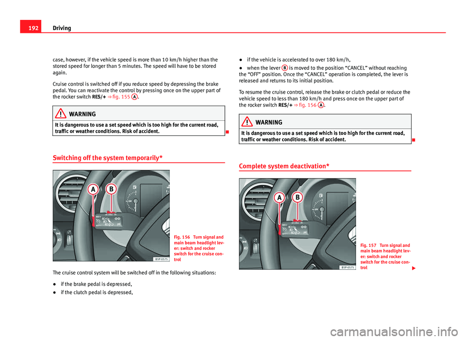
Fig. 156 Turn signal and
main beam headlight lev-
er: switch and rocker
switch for the cruise con-
trol
The cruise control system will be switched off in the following situations:
● if the brake pedal is depressed,
● if the clutch pedal is depressed, ●
if the vehicle is accelerated to over 180 km/h,
● when the lever B
is moved to the position “CANCEL” without reaching
the “OFF” position. Once the “CANCEL” operation is completed, the lever is
released and returns to its initial position.
To resume the cruise control, release the brake or clutch pedal or reduce the
vehicle speed to less than 180 km/h and press once on the upper part of
the rocker switch RES/+ ⇒ fig. 156 A
.
WARNING
It is dangerous to use a set speed which is too high for the current road,
traffic or weather conditions. Risk of accident.
Complete system deactivation*
Fig. 157 Turn signal and
main beam headlight lev-
er: switch and rocker
switch for the cruise con-
trol
Page 209 of 315
207
Driving and the environment
Driving abroad Observations
To drive abroad, the following must be taken into consideration:
● For vehicles fitted with a catalytic converter ensure that unleaded petrol
is available for the journey. See the chapter “Refuelling”. Automobile organ-
isations will have information about service station networks selling unlea-
ded fuel.
● In some countries, it is possible that your vehicle model is not sold, and
therefore spare parts are not available or the Authorised Services can only
carry out limited repairs.
SEAT importers and distributors will gladly provide information about the
technical preparations that you vehicle requires and also about necessary
maintenance and repair possibilities.
Adhesive strips for headlights
If you have to drive a right-hand drive vehicle in a left-hand drive country, or
vice versa, the asymmetric dipped beam headlights will dazzle oncoming
traffic.
To prevent dazzling, you must apply stickers to certain parts of the head-
light lenses. Further information is available at your Authorised Service Cen-
tre.
In vehicles with adaptive headlights, the rotation system must previously be
disconnected. To do this, please go to a specialised workshop.
Safety FirstOperating InstructionsPractical TipsTechnical Specifications
Page 241 of 315
239
Checking and refilling levels
WARNING
Any work carried out in the engine compartment or on the engine must
be carried out cautiously.
● When working in the engine compartment, always observe the safety
warnings ⇒ page 230.
● When the engine is warm or hot, the cooling system is pressurised!
Do not unscrew the cap on the expansion tank when the engine is hot.
This is a burn injury risk.
CAUTION
● When mixed with other additives the colour of G12 will change to brown.
If this occurs you should have the coolant changed immediately. Failure to
do so will result in engine damage!
● If a lot of coolant fluid has been lost, wait for the engine to cool down
before putting in cold coolant. This avoids damaging the engine. Large cool-
ant losses are an indication of leaks in the cooling system. See a special-
ised workshop immediately and have the cooling system checked. Other-
wise, there is a risk of engine damage. Washer fluid and windscreen wiper blades
Topping up washer fluid
The water for cleaning the windscreen should always be
mixed with washer fluid.
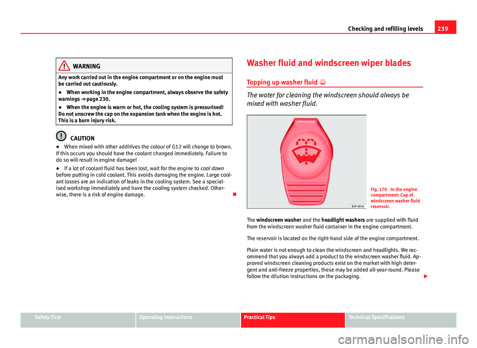
Fig. 170 In the engine
compartment: Cap of
windscreen washer fluid
reservoir.
The windscreen washer and the headlight washers are supplied with fluid
from the windscreen washer fluid container in the engine compartment.
The reservoir is located on the right-hand side of the engine compartment.
Plain water is not enough to clean the windscreen and headlights. We rec-
ommend that you always add a product to the windscreen washer fluid. Ap-
proved windscreen cleaning products exist on the market with high deter-
gent and anti-freeze properties, these may be added all-year-round. Please
follow the dilution instructions on the packaging.
Safety FirstOperating InstructionsPractical TipsTechnical Specifications
Page 270 of 315
268If and when
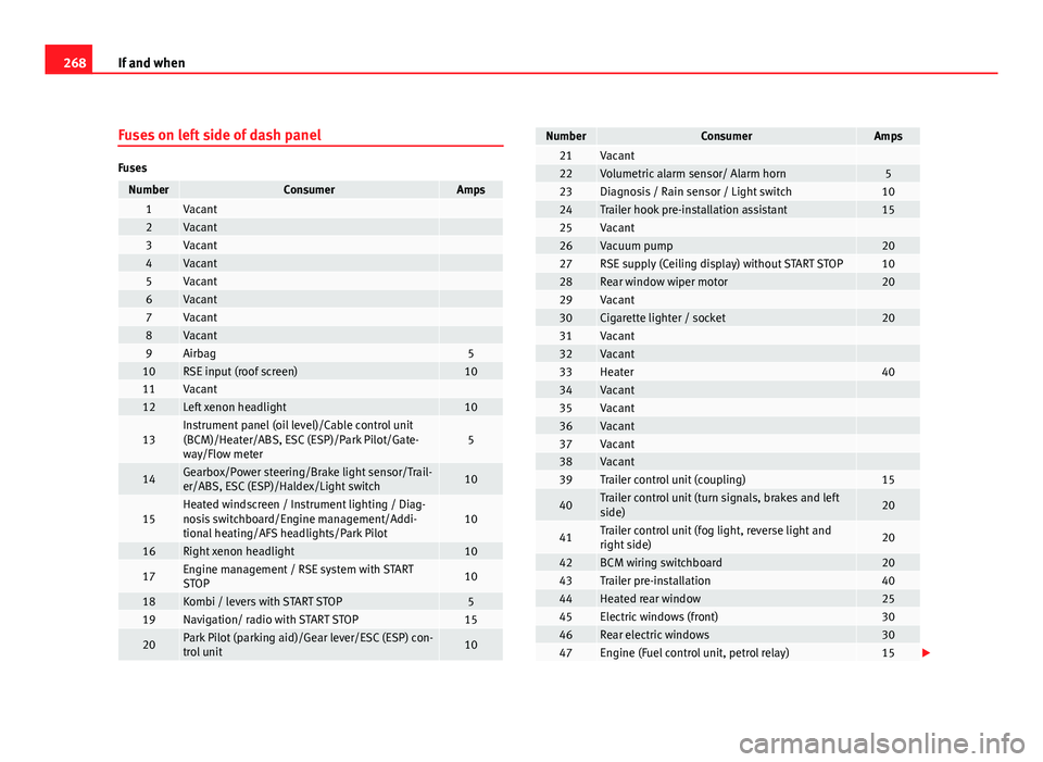
Fuses on left side of dash panel
Fuses
NumberConsumerAmps1Vacant 2Vacant 3Vacant 4Vacant 5Vacant 6Vacant 7Vacant 8Vacant 9Airbag510RSE input (roof screen)1011Vacant 12Left xenon headlight10
13Instrument panel (oil level)/Cable control unit
(BCM)/Heater/ABS, ESC (ESP)/Park Pilot/Gate-
way/Flow meter5
14Gearbox/Power steering/Brake light sensor/Trail-
er/ABS, ESC (ESP)/Haldex/Light switch10
15Heated windscreen / Instrument lighting / Diag-
nosis switchboard/Engine management/Addi-
tional heating/AFS headlights/Park Pilot10
16Right xenon headlight10
17Engine management / RSE system with START
STOP10
18Kombi / levers with START STOP519Navigation/ radio with START STOP15
20Park Pilot (parking aid)/Gear lever/ESC (ESP) con-
trol unit10
NumberConsumerAmps21Vacant 22Volumetric alarm sensor/ Alarm horn523Diagnosis / Rain sensor / Light switch1024Trailer hook pre-installation assistant1525Vacant 26Vacuum pump2027RSE supply (Ceiling display) without START STOP1028Rear window wiper motor2029Vacant 30Cigarette lighter / socket2031Vacant 32Vacant 33Heater4034Vacant 35Vacant 36Vacant 37Vacant 38Vacant 39Trailer control unit (coupling)15
40Trailer control unit (turn signals, brakes and left
side)20
41Trailer control unit (fog light, reverse light and
right side)20
42BCM wiring switchboard2043Trailer pre-installation4044Heated rear window2545Electric windows (front)3046Rear electric windows3047Engine (Fuel control unit, petrol relay)15
Page 271 of 315
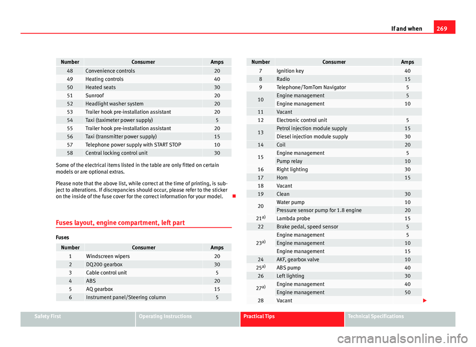
269
If and when
NumberConsumerAmps48Convenience controls2049Heating controls4050Heated seats3051Sunroof2052Headlight washer system2053Trailer hook pre-installation assistant2054Taxi (taximeter power supply)555Trailer hook pre-installation assistant2056Taxi (transmitter power supply)1557Telephone power supply with START STOP1058Central locking control unit30
Some of the electrical items listed in the table are only fitted on certain
models or are optional extras.
Please note that the above list, while correct at the time of printing, is sub-
ject to alterations. If discrepancies should occur, please refer to the sticker
on the inside of the fuse cover for the correct information for your model.
Fuses layout, engine compartment, left part
Fuses
NumberConsumerAmps1Windscreen wipers202DQ200 gearbox303Cable control unit54ABS205AQ gearbox156Instrument panel/Steering column5
NumberConsumerAmps7Ignition key408Radio159Telephone/TomTom Navigator5
10Engine management5Engine management1011Vacant 12Electronic control unit5
13Petrol injection module supply15Diesel injection module supply3014Coil20
15Engine management5Pump relay1016Right lighting3017Horn1518Vacant 19Clean30
20Water pump10Pressure sensor pump for 1.8 engine2021 a)Lambda probe1522Brake pedal, speed sensor5
23a)Engine management5Engine management10Engine management1524AKF, gearbox valve1025a)ABS pump4026Left lighting30
27a)Engine management40Engine management5028Vacant
Safety FirstOperating InstructionsPractical TipsTechnical Specifications
Page 272 of 315
270If and when
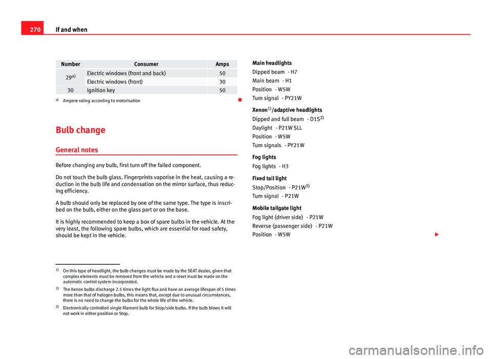
NumberConsumerAmps
29a)Electric windows (front and back)50Electric windows (front)3030Ignition key50a)
Ampere rating according to motorisation
Bulb change General notes
Before changing any bulb, first turn off the failed component.
Do not touch the bulb glass. Fingerprints vaporise in the heat, causing a re-
duction in the bulb life and condensation on the mirror surface, thus reduc-
ing efficiency.
A bulb should only be replaced by one of the same type. The type is inscri-
bed on the bulb, either on the glass part or on the base.
It is highly recommended to keep a box of spare bulbs in the vehicle. At the
very least, the following spare bulbs, which are essential for road safety,
should be kept in the vehicle. Main headlights
- H7
- H1
- W5W - PY21W
Xenon 1)
/adaptive headlights
- D1S2)
- P21W SLL
- W5W - PY21W
Fog lights - H3
Fixed tail light - P21W3)
- P21W
Mobile tailgate light - P21W- P21W
- W5W
Dipped beam
Main beam
Position
Turn signal
Dipped and full beam
Daylight
Position
Turn signals
Fog lights
Stop/Position
Turn signal
Fog light (driver side)
Reverse (passenger side)
Position
1)
On this type of headlight, the bulb changes must be made by the SEAT dealer, given that
complex elements must be removed from the vehicle and a reset must be made on the
automatic control system incorporated.
2) The Xenon bulbs discharge 2.5 times the light flux and have an average lifespan of 5 times
more than that of halogen bulbs, this means that, except due to unusual circumstances,
there is no need to change the bulbs for the whole life of the vehicle.
3) Electronically controlled single filament bulb for Stop/side bulbs. If the bulb blows it will
not work in either position or Stop.