instrument panel Seat Altea XL 2014 Owner's Manual
[x] Cancel search | Manufacturer: SEAT, Model Year: 2014, Model line: Altea XL, Model: Seat Altea XL 2014Pages: 321, PDF Size: 4.52 MB
Page 5 of 321
Table of Contents
About this manual . . . . . . . . . . . . . . . . . . . 5
Content . . . . . . . . . . . . . . . . . . . . . . . . . . . . . . . . 6
Safety First . . . . . . . . . . . . . . . . . . . . . . . . . . . . 7
Safe driving . . . . . . . . . . . . . . . . . . . . . . . . . . . . . . . 7
Brief introduction . . . . . . . . . . . . . . . . . . . . . . . . . 7
Proper sitting position for occupants . . . . . . . . . 10
Pedal area . . . . . . . . . . . . . . . . . . . . . . . . . . . . . . . 16
Storing objects . . . . . . . . . . . . . . . . . . . . . . . . . . . 17
Seat belts . . . . . . . . . . . . . . . . . . . . . . . . . . . . . . . . . 19
Brief introduction . . . . . . . . . . . . . . . . . . . . . . . . . 19
Why wear seat belts? . . . . . . . . . . . . . . . . . . . . . . 21
Seat belts . . . . . . . . . . . . . . . . . . . . . . . . . . . . . . . 25
Seat belt tensioners . . . . . . . . . . . . . . . . . . . . . . . 29
Airbag system . . . . . . . . . . . . . . . . . . . . . . . . . . . . . 30
Brief introduction . . . . . . . . . . . . . . . . . . . . . . . . . 30
Front airbags . . . . . . . . . . . . . . . . . . . . . . . . . . . . . 34
Side airbags* . . . . . . . . . . . . . . . . . . . . . . . . . . . . 37
Curtain airbags . . . . . . . . . . . . . . . . . . . . . . . . . . . 41
Deactivating airbags* . . . . . . . . . . . . . . . . . . . . . . 44
Child safety . . . . . . . . . . . . . . . . . . . . . . . . . . . . . . . 46
Brief introduction . . . . . . . . . . . . . . . . . . . . . . . . . 46
Child seats . . . . . . . . . . . . . . . . . . . . . . . . . . . . . . . 48
Securing child seats . . . . . . . . . . . . . . . . . . . . . . . 51 Operating instructions
. . . . . . . . . . . . . 55
Cockpit . . . . . . . . . . . . . . . . . . . . . . . . . . . . . . . . . . . 55
Overview . . . . . . . . . . . . . . . . . . . . . . . . . . . . . . . . 55
Instruments . . . . . . . . . . . . . . . . . . . . . . . . . . . . . . 57
LPG system* . . . . . . . . . . . . . . . . . . . . . . . . . . . . . 60
Digital instrument panel display . . . . . . . . . . . . . 61
Instrument panel menus* . . . . . . . . . . . . . . . . . . . 68
Warning lamps . . . . . . . . . . . . . . . . . . . . . . . . . . . 76
Steering wheel controls . . . . . . . . . . . . . . . . . . . . 90
General information . . . . . . . . . . . . . . . . . . . . . . . 90
Audio system . . . . . . . . . . . . . . . . . . . . . . . . . . . . . 91
Radio navigation system . . . . . . . . . . . . . . . . . . . 94
Opening and closing . . . . . . . . . . . . . . . . . . . . . . 96
Central locking . . . . . . . . . . . . . . . . . . . . . . . . . . . 96
Keys . . . . . . . . . . . . . . . . . . . . . . . . . . . . . . . . . . . . 102
Radio frequency remote control . . . . . . . . . . . . . . 104
Anti-theft alarm system* . . . . . . . . . . . . . . . . . . . 106
Rear lid . . . . . . . . . . . . . . . . . . . . . . . . . . . . . . . . . . 108
Windows . . . . . . . . . . . . . . . . . . . . . . . . . . . . . . . . 110
Sliding/tilting sunroof* . . . . . . . . . . . . . . . . . . . . 112
Lights and visibility . . . . . . . . . . . . . . . . . . . . . . . . 115
Lights . . . . . . . . . . . . . . . . . . . . . . . . . . . . . . . . . . . 115
Interior lights . . . . . . . . . . . . . . . . . . . . . . . . . . . . . 123
Visibility . . . . . . . . . . . . . . . . . . . . . . . . . . . . . . . . . 126
Windscreen wipers . . . . . . . . . . . . . . . . . . . . . . . . 127
Rear vision mirrors . . . . . . . . . . . . . . . . . . . . . . . . 131
Seats and storage . . . . . . . . . . . . . . . . . . . . . . . . . 134
The importance of correct seat adjustment . . . . . 134
Head restraints . . . . . . . . . . . . . . . . . . . . . . . . . . . 135
Front seats . . . . . . . . . . . . . . . . . . . . . . . . . . . . . . . 137
Rear seats . . . . . . . . . . . . . . . . . . . . . . . . . . . . . . . 139
Storage compartment . . . . . . . . . . . . . . . . . . . . . . 141
Multi-purpose mobile storage compartment* . . 148 Ashtray*, cigarette lighter* and power sockets . 150
First-aid kit, warning triangle, fire extinguisher . 154
Luggage compartment . . . . . . . . . . . . . . . . . . . . . 154
Air conditioning . . . . . . . . . . . . . . . . . . . . . . . . . . . 159
Heating . . . . . . . . . . . . . . . . . . . . . . . . . . . . . . . . . 159
Climatic* . . . . . . . . . . . . . . . . . . . . . . . . . . . . . . . . 161
2C-Climatronic* . . . . . . . . . . . . . . . . . . . . . . . . . . . 164
General notes . . . . . . . . . . . . . . . . . . . . . . . . . . . . 169
Driving . . . . . . . . . . . . . . . . . . . . . . . . . . . . . . . . . . . . 171
Steering . . . . . . . . . . . . . . . . . . . . . . . . . . . . . . . . . 171
Safety . . . . . . . . . . . . . . . . . . . . . . . . . . . . . . . . . . . 172
Ignition lock . . . . . . . . . . . . . . . . . . . . . . . . . . . . . . 173
Starting and stopping the engine . . . . . . . . . . . . 174
Start-Stop function* . . . . . . . . . . . . . . . . . . . . . . . 179
Manual gearbox . . . . . . . . . . . . . . . . . . . . . . . . . . 182
Automatic gearbox/DSG automatic gearbox* . . . 183
Handbrake . . . . . . . . . . . . . . . . . . . . . . . . . . . . . . . 188
Parking aid acoustic system* . . . . . . . . . . . . . . . . 190
Cruise speed* (Cruise control system) . . . . . . . . 193
Practical Tips . . . . . . . . . . . . . . . . . . . . . . . . . 196
Intelligent technology . . . . . . . . . . . . . . . . . . . . . 196
Brakes . . . . . . . . . . . . . . . . . . . . . . . . . . . . . . . . . . 196
Anti-lock brake and traction control systems M-
ABS (ABS and ASR) . . . . . . . . . . . . . . . . . . . . . . . . 197
Electronic Stability Control (ESC)* . . . . . . . . . . . . 198
Driving and the environment . . . . . . . . . . . . . . . 204
Running-in . . . . . . . . . . . . . . . . . . . . . . . . . . . . . . . 204
Exhaust gas purification system . . . . . . . . . . . . . 205
Economical and environmentally friendly driving 206
Driving abroad . . . . . . . . . . . . . . . . . . . . . . . . . . . . 208
3
Table of Contents
Page 34 of 321
32Airbag system
Control lamp for airbag and seat belt tensioner
This control lamp monitors the airbag and seat belt tension-
er system.
The control lamp monitors all airbags and seat belt tensioners in the vehi-
cle, including control units and wiring connections.
Monitoring of airbag and belt tensioner system
Both the airbag and belt tensioner systems operation is constantly moni-
tored electronically. Each time the ignition is switched on, the control lamp
lights for several seconds and the instrument panel display* shows AIR-
BAG/TENSIONER.
The system must be checked when the control lamp :
● does not light up when the ignition is switched on
● turns off after 4 seconds after the ignition is switched on
● turns off and then lights up again after the ignition is switched on
● lights up or flashes while the vehicle is moving
In the event of a malfunction, the warning lamp remains on continuously. In
addition, depending on the malfunction, a fault message appears in the in-
strument panel display for approx. 10 seconds and a short audible warning
is given. In this event, you should have a specialised workshop check the
system immediately.
If any of the airbags are disabled by a Technical Service, the warning lamp
lights for several seconds more after the verification and will turn off if there
is no fault.WARNING
● If there is a malfunction, the airbag and belt tensioner system cannot
properly perform its protective function.
● If a malfunction occurred, have the system checked immediately by a
specialised workshop. Otherwise, in the event of an accident, the airbag
system and belt tensioners may not be triggered, or may not be triggered
correctly.
Repairs, maintenance and disposal of airbags
The parts of the airbag system are installed in various places in your vehi-
cle. If work is carried out on the airbag system or parts have to be removed
and fitted on the system when performing other repair work, parts of the air-
bag system may be damaged. In the event of an accident this could cause
the airbag to inflate incorrectly or not inflate at all.
The relevant safety requirements must be observed when the vehicle or
components of the airbag are scrapped. Specialised workshops and vehicle
disposal centres are familiar with these requirements.
WARNING
● If repairs are not carried out by a professional, or if the airbags are
used incorrectly, the risk of severe or fatal injuries is increased. The air-
bags may fail to inflate, or could inflate in the wrong circumstances.
● Do not cover or stick anything on the steering wheel hub or the sur-
face of the airbag unit on the passenger side of the dash panel, and do
not obstruct or modify them in any way.
● It is important not to attach any objects such as cup holders or tele-
phone mountings to the surfaces covering the airbag units.
Page 46 of 321
44Airbag system
Deactivating airbags*
Front passenger front airbag deactivation
If you fit a rear-facing child seat to the front passenger seat,
the front passenger front airbag must be de-activated.
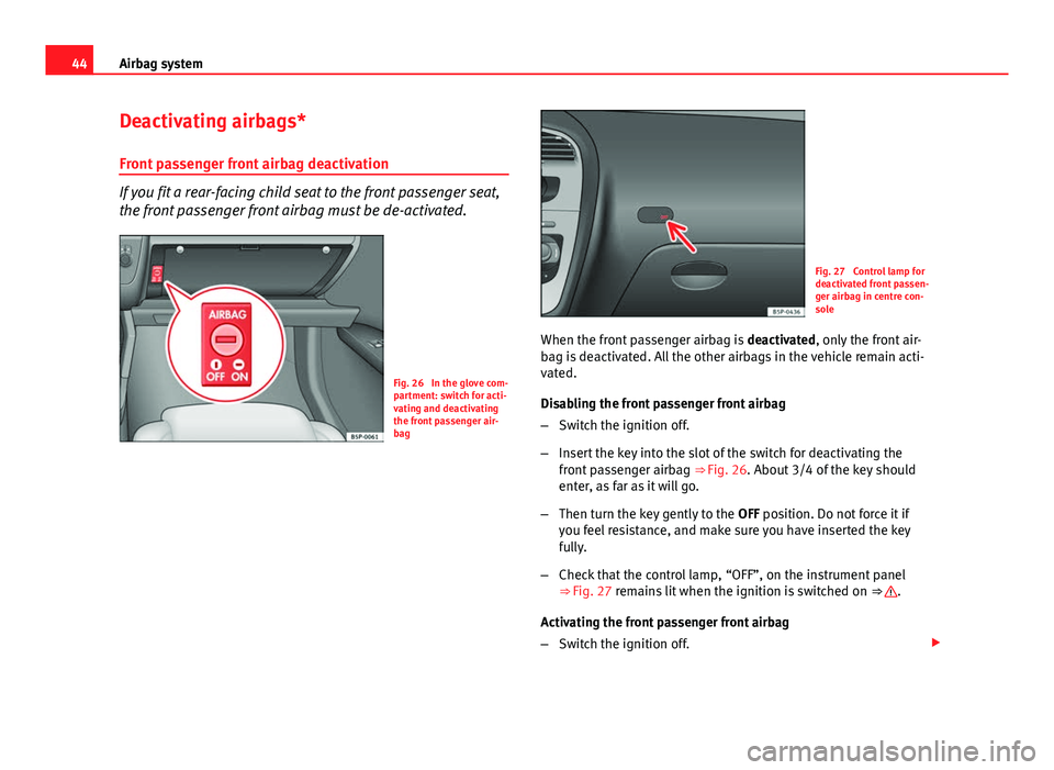
Fig. 26 In the glove com-
partment: switch for acti-
vating and deactivating
the front passenger air-
bag
Fig. 27 Control lamp for
deactivated front passen-
ger airbag in centre con-
sole
When the front passenger airbag is deactivated, only the front air-
bag is deactivated. All the other airbags in the vehicle remain acti-
vated.
Disabling the front passenger front airbag
– Switch the ignition off.
– Insert the key into the slot of the switch for deactivating the
front passenger airbag ⇒ Fig. 26. About 3/4 of the key should
enter, as far as it will go.
– Then turn the key gently to the OFF position. Do not force it if
you feel resistance, and make sure you have inserted the key
fully.
– Check that the control lamp, “OFF”, on the instrument panel
⇒ Fig. 27 remains lit when the ignition is switched on ⇒
.
Activating the front passenger front airbag
– Switch the ignition off.
Page 47 of 321
45
Airbag system
– Insert the key into the slot of the switch for deactivating the
front passenger airbag ⇒ Fig. 26. About 3/4 of the key should
enter, as far as it will go.
– Then turn the key gently to the ON position. Do not force it if you
feel resistance, and make sure you have inserted the key fully.
– Check that the control lamp on the instrument panel ⇒ Fig. 27
does not light up when the ignition is switched on ⇒
.
WARNING
● The driver is responsible for the proper position of the key-operated
switch.
● You should only deactivate the front passenger front airbag when, in
exceptional cases, you have to use a rear-facing child seat on the front
passenger seat ⇒ page 46, Child safety.
● Never install a child seat facing backwards on the front passenger
seat unless the front passenger front airbag has been disabled. Other-
wise, there is a risk of death.
● As soon as the child seat is no longer needed on the front passenger
seat, enable the front passenger front airbag again.
● Only deactivate the front passenger front airbag when the ignition is
off, otherwise a fault may occur in the airbag system, which could cause
the airbag to not deploy properly or not deploy at all.
● Never leave the key in the airbag deactivation switch as it could get
damaged or activate or deactivate the airbag during driving.
WARNING (Continued)
● When the front passenger front airbag is deactivated, if the control
lamp AIRBAG OFF is not continuously lit up, there may be a fault in the
airbag system:
–Have the airbag system inspected immediately by a specialised
workshop.
– Do not use a child seat on the front passenger seat! The front pas-
senger front airbag could be triggered despite the fact that there is a
fault in the system and, as a result, a child could sustain serious or
fatal injuries.
– It is unpredictable whether the front passenger airbag will deploy
in the event of an accident. Warn all your passengers of this.
● When using the ignition key to activate/deactivate the front passen-
ger front airbag, only the front passenger airbag will be activated/deacti-
vated. The side airbag and head airbag on the passenger side will remain
active.
Safety FirstOperating instructionsPractical TipsTechnical Specifications
Page 57 of 321
55
Cockpit
Operating instructions Cockpit
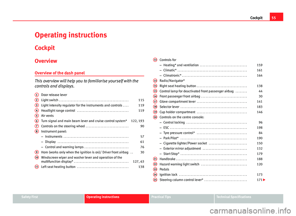
Overview Overview of the dash panel
This overview will help you to familiarise yourself with the
controls and displays. Door release lever
Light switch . . . . . . . . . . . . . . . . . . . . . . . . . . . . . . . . . . . . . . . . . . . . . . . 115
Light intensity regulator for the instruments and controls . . . .119
Headlight range control . . . . . . . . . . . . . . . . . . . . . . . . . . . . . . . . . . . 119
Air vents
Turn signal and main beam lever and cruise control system* 122, 193
Controls on the steering wheel . . . . . . . . . . . . . . . . . . . . . . . . . . . . . 90
Instrument panel:
– Instruments . . . . . . . . . . . . . . . . . . . . . . . . . . . . . . . . . . . . . . . . . . . . 57
– Display . . . . . . . . . . . . . . . . . . . . . . . . . . . . . . . . . . . . . . . . . . . . . . . . 61
– Control and warning lamps . . . . . . . . . . . . . . . . . . . . . . . . . . . . . . 76
Horn (works only when the ignition is on)/ Driver front airbag . .30
Windscreen wiper and washer lever and operation of the
multifunction display* . . . . . . . . . . . . . . . . . . . . . . . . . . . . . . . . . . . . . 127, 63
Left seat heating button . . . . . . . . . . . . . . . . . . . . . . . . . . . . . . . . . . . 138
1
2345678
910
11
Controls for
–
Heating* and ventilation . . . . . . . . . . . . . . . . . . . . . . . . . . . . . . . . 159
– Climatic* . . . . . . . . . . . . . . . . . . . . . . . . . . . . . . . . . . . . . . . . . . . . . . . 161
– Climatronic* . . . . . . . . . . . . . . . . . . . . . . . . . . . . . . . . . . . . . . . . . . . . 164
Radio/Navigator*
Right seat heating button . . . . . . . . . . . . . . . . . . . . . . . . . . . . . . . . . . 138
Control lamp for deactivated front passenger airbag . . . . . . . .44
Front passenger front airbag . . . . . . . . . . . . . . . . . . . . . . . . . . . . . . . 30
Glove compartment lever . . . . . . . . . . . . . . . . . . . . . . . . . . . . . . . . . . 141
Selector lever . . . . . . . . . . . . . . . . . . . . . . . . . . . . . . . . . . . . . . . . . . . . . 183
Cup holder compartment . . . . . . . . . . . . . . . . . . . . . . . . . . . . . . . . . . 146
Controls on the centre console:
– Central locking . . . . . . . . . . . . . . . . . . . . . . . . . . . . . . . . . . . . . . . . . 96
– ESC . . . . . . . . . . . . . . . . . . . . . . . . . . . . . . . . . . . . . . . . . . . . . . . . . . . . 198
– Tyre pressure control* . . . . . . . . . . . . . . . . . . . . . . . . . . . . . . . . . . 84
– Park Pilot* . . . . . . . . . . . . . . . . . . . . . . . . . . . . . . . . . . . . . . . . . . . . . 190
– Cigarette lighter/Power socket . . . . . . . . . . . . . . . . . . . . . . . . . . 150
– Exterior mirror adjustment . . . . . . . . . . . . . . . . . . . . . . . . . . . . . . 132
– Start-Stop* . . . . . . . . . . . . . . . . . . . . . . . . . . . . . . . . . . . . . . . . . . . . . 179
Handbrake . . . . . . . . . . . . . . . . . . . . . . . . . . . . . . . . . . . . . . . . . . . . . . . . 188
Hazard warning light switch . . . . . . . . . . . . . . . . . . . . . . . . . . . . . . . 120
Pedals
Ignition lock . . . . . . . . . . . . . . . . . . . . . . . . . . . . . . . . . . . . . . . . . . . . . . 173
Steering column control lever* . . . . . . . . . . . . . . . . . . . . . . . . . . . . . 171
12
1314151617181920
2122232425
Safety FirstOperating instructionsPractical TipsTechnical Specifications
Page 59 of 321
57
Cockpit
Instruments Instrument overview
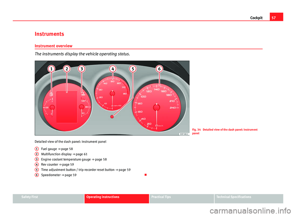
The instruments display the vehicle operating status.
Fig. 34 Detailed view of the dash panel: instrument
panel
Detailed view of the dash panel: instrument panel Fuel gauge ⇒ page 58
Multifunction display ⇒ page 61
Engine coolant temperature gauge ⇒ page 58
Rev counter ⇒ page 59
Time adjustment button / trip recorder reset button ⇒ page 59
Speedometer ⇒ page 59
1
23456
Safety FirstOperating instructionsPractical TipsTechnical Specifications
Page 60 of 321
58Cockpit
Fuel gauge and reserve indicator
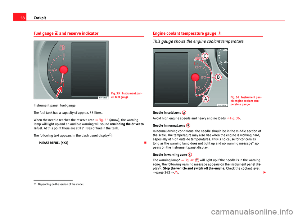
Fig. 35 Instrument pan-
el: fuel gauge
Instrument panel: fuel gauge
The fuel tank has a capacity of approx. 55 litres.
When the needle reaches the reserve area ⇒ Fig. 35 (arrow), the warning
lamp will light up and an audible warning will sound reminding the driver to
refuel. At this point there are still 7 litres of fuel in the tank.
The following text appears in the dash panel display 1)
:
PLEASE REFUEL [XXX] Engine coolant temperature gauge
This gauge shows the engine coolant temperature.
Fig. 36 Instrument pan-
el: engine coolant tem-
perature gauge
Needle in cold zone A
Avoid high engine speeds and heavy engine loads
⇒ Fig. 36.
Needle in normal zone B
In normal driving conditions, the needle should be in the middle section of
the scale. The temperature may also rise when the engine is working hard,
especially at high outside temperatures. This is no cause for concern as
long as the warning lamp does not light up and no warning message* ap-
pears on the instrument panel display.
Needle in warning zone C
The warning lamp* ⇒ Fig. 48 2 will light up if the needle is in the warning
zone. The following warning message appears on the instrument panel dis-
play 1)
. Stop the vehicle and switch off the engine. Check the coolant level
⇒ page 242 ⇒
.
1)
Depending on the version of the model.
Page 61 of 321
59
Cockpit
Even if the coolant level is correct do not continue driving. You should ob-
tain technical assistance.
WARNING
When working in the engine compartment, always observe the safety
warnings ⇒ page 235.
CAUTION
Accessories in front of the air inlet reduce the cooling effect of the coolant.
At high outside temperatures and high engine loads, there is a risk of the
engine overheating.
Rev counter
The rev counter displays the engine speed in revolutions per
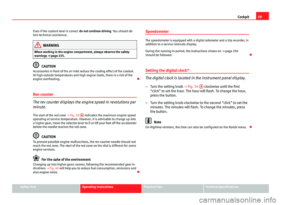
minute. The start of the red zone ⇒ Fig. 34 4
indicates the maximum engine speed
operating at service temperature. However, it is advisable to change up into
a higher gear, move the selector lever to D or lift your foot off the accelerator
before the needle reaches the red zone.
CAUTION
To prevent possible engine malfunctions, the rev counter needle should not
reach the red zone. The start of the red zone on the dial is different for some
engine versions.
For the sake of the environment
Changing up into higher gears sooner, following the recommended gear in-
dications ⇒ Fig. 40 will help you to reduce fuel consumption, emissions and
also engine noise. Speedometer
The speedometer is equipped with a digital odometer and a trip recorder, in
addition to a service intervals display.
During the running-in period, the instructions shown on
⇒ page 204
should be followed.
Setting the digital clock*
The digital clock is located in the instrument panel display.
– Turn the setting knob ⇒ Fig. 34 5
clockwise until the first
“click” to set the hour. The hour will flash. To change the hour,
press the button.
– Turn the setting knob clockwise to the second “click” to set the
minutes. The minutes will flash. To change the minutes, press
the button.
Note
On Highline versions, the time can also be configured on the Kombi menu.
Safety FirstOperating instructionsPractical TipsTechnical Specifications
Page 62 of 321
60Cockpit
LPG system*
Applies to the model: ALTEA / ALTEA XL LPG gauge
Fig. 37 Instrument pan-
el: gas gauge.
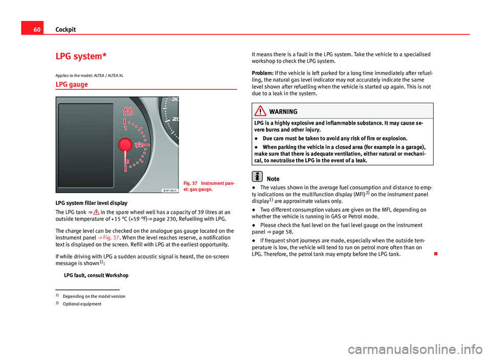
LPG system filler level display
The LPG tank ⇒
in the spare wheel well has a capacity of 39 litres at an
outside temperature of +15 °C (+59 °F)⇒ page 230, Refuelling with LPG.
The charge level can be checked on the analogue gas gauge located on the
instrument panel ⇒ Fig. 37. When the level reaches reserve, a notification
text is displayed on the screen. Refill with LPG at the earliest opportunity.
If while driving with LPG a sudden acoustic signal is heard, the on-screen
message is shown 1)
:
LPG fault, consult Workshop It means there is a fault in the LPG system. Take the vehicle to a specialised
workshop to check the LPG system.
Problem: If the vehicle is left parked for a long time immediately after refuel-
ling, the natural gas level indicator may not accurately indicate the same
level shown after refuelling when the vehicle is started up again. This is not
due to a leak in the system.
WARNING
LPG is a highly explosive and inflammable substance. It may cause se-
vere burns and other injury.
● Due care must be taken to avoid any risk of fire or explosion.
● When parking the vehicle in a closed area (for example in a garage),
make sure that there is adequate ventilation, either natural or mechani-
cal, to neutralise the LPG in the event of a leak.
Note
● The values shown in the average fuel consumption and distance to emp-
ty indications on the multifunction display (MFI) 2)
on the instrument panel
display 1)
are approximate values only.
● Two different consumption values are given on the MFI, depending on
whether the vehicle is running in GAS or Petrol mode.
● Please check the fuel level on the fuel level gauge on the instrument
panel ⇒ page 58.
● If frequent short journeys are made, especially when the outside tem-
perature is low, the vehicle will tend to run on petrol more often than on
LPG. Therefore, the petrol tank may empty before the LPG tank.
1)
Depending on the model version
2) Optional equipment
Page 63 of 321
61
Cockpit
Digital instrument panel display
Display (without warning or information texts)
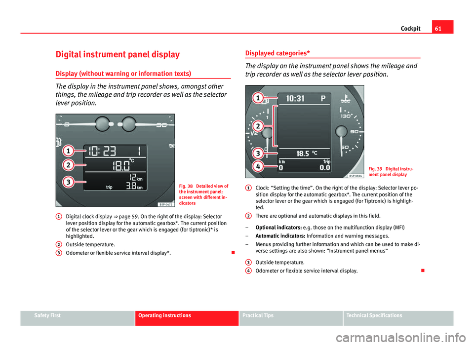
The display in the instrument panel shows, amongst other
things, the mileage and trip recorder as well as the selector
lever position.
Fig. 38 Detailed view of
the instrument panel:
screen with different in-
dicators
Digital clock display ⇒ page 59. On the right of the display: Selector
lever position display for the automatic gearbox*. The current position
of the selector lever or the gear which is engaged (for tiptronic)* is
highlighted.
Outside temperature.
Odometer or flexible service interval display*.
1
23
Displayed categories*
The display on the instrument panel shows the mileage and
trip recorder as well as the selector lever position.
Fig. 39 Digital instru-
ment panel display
Clock: “Setting the time”. On the right of the display: Selector lever po-
sition display for the automatic gearbox*. The current position of the
selector lever or the gear which is engaged (for Tiptronic) is highligh-
ted.
There are optional and automatic displays in this field.
Optional indicators: e.g. those on the multifunction display (MFI)
Automatic indicators: Information and warning messages.
Menus providing further information and which can be used to make di-
verse settings are also shown: “Instrument panel menus”
Outside temperature.
Odometer or flexible service interval display.
1
2
–
–
–
3
4
Safety FirstOperating instructionsPractical TipsTechnical Specifications