technical specifications Seat Altea XL 2015 User Guide
[x] Cancel search | Manufacturer: SEAT, Model Year: 2015, Model line: Altea XL, Model: Seat Altea XL 2015Pages: 236, PDF Size: 4.23 MB
Page 25 of 236
Airbag system
●
Any work on the head-protection airbag
system or removal and installation of the air-
bag components for other repairs (such as re-
moval of the roof lining) should only be per-
formed by a specialised workshop. Other-
wise, faults may occur during the airbag sys-
tem operation.
● Do not attempt to modify components of
the airbag system in any way.
● The side and head airbags are managed
through sensors located in the interior of the
front doors. To ensure the correct operation of
the side and curtain airbags, neither the
doors nor the door panels should be modified
in any way (e.g. fitting loudspeakers). If the
front door is damaged, the airbag system
may not work correctly. All work carried out
on the front door must be done in a special-
ised workshop. Deactivating airbags
Front passenger front airbag
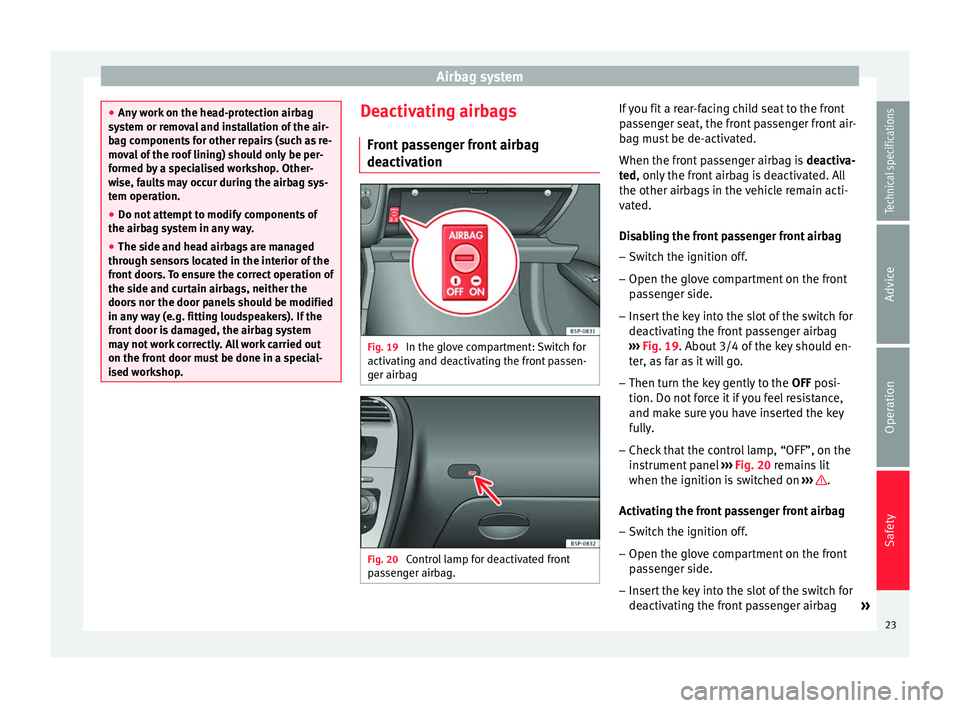
deactivation Fig. 19
In the glove compartment: Switch for
activating and deactivating the front passen-
ger airbag Fig. 20
Control lamp for deactivated front
passenger airbag. If you fit a rear-facing child seat to the front
passenger seat, the front passenger front air-
bag must be de-activated.
When the front passenger airbag is
deactiva-
ted , only the front airbag is deactivated. All
the other airb ag
s in the vehicle remain acti-
vated.
Disabling the front passenger front airbag
– Switch the ignition off.
– Open the glove compartment on the front
passenger side.
– Insert the key into the slot of the switch for
deactivating the front passenger airbag
››› Fig. 19. About 3/4 of the key should en-
ter
, as far as it will go.
– Then turn the key gently to the OFF posi-
tion. Do not f
orce it if you feel resistance,
and make sure you have inserted the key
fully.
– Check that the control lamp, “OFF”, on the
instrument panel ››› Fig. 20 remains lit
when the ignition is
switched on ››› .
Activating the front passenger front airbag – Switch the ignition off.
– Open the glove compartment on the front
passenger side.
– Insert the key into the slot of the switch for
deactivating the front passenger airbag
»
23
Technical specifications
Advice
Operation
Safety
Page 27 of 236
Transporting children safety
Follow the manufacturer's instructions and
observe any statutory requirements when in-
stalling and using child seats. Always read
and note ››› page 25 .
W e r
ecommend you always carry the manu-
facturer's Child Seat Instruction Manual to-
gether with the on-board documentation.
Important information regarding the
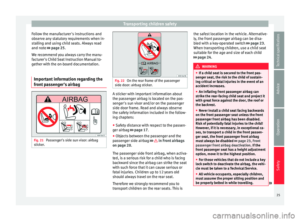
front passenger's airbag Fig. 21
Passenger's side sun visor: airbag
sticker. Fig. 22
On the rear frame of the passenger
side door: airbag sticker. A sticker with important information about
the passenger airbag is located on the pas-
senger's sun visor and/or on the passenger
side door frame. Read and always observe
the safety information included in the follow-
ing chapters:
● Safety distance with respect to the passen-
ger airbag ››› page 17 .
● Ob
jects between the passenger and the
passenger side airbag ››› in Front airbags
on page 20 .
The p a
ssenger side front airbag, when activa-
ted, is a serious risk for a child who is facing
backward since the airbag can strike the seat
with such force that it can cause serious or
fatal injuries. Children up to 12 years old
should always travel on the rear seat.
Therefore we strongly recommend you to
transport children on the rear seats. This is the safest location in the vehicle. Alternative-
ly, the front passenger airbag can be disa-
bled with a key-operated switch
››› page 23.
When transporting children, use a child seat
suitable for the age and size of each child
››› page 24. WARNING
● If a child seat is secured to the front pas-
senger seat, the risk to the child of sustain-
ing critical or fatal injuries in the event of an
accident increases.
● An inflating front passenger airbag can
strike the rear-facing child seat and project it
with great force against the door, the roof or
the backrest.
● Never install a child seat facing backwards
on the front passenger seat unless the front
passenger front airbag has been disabled.
Risk of potentially fatal injuries to the child!
However, if it is necessary, in exceptional ca-
ses, to transport a child in the front passen-
ger seat, the front passenger front airbag
must always be disabled ››› page 23, Front
passenger front airbag deactivation . If the
front passenger seat has a height adjustment
option, move it to the highest position.
● For those vehicles that do not include a key
lock switch to deactivate the airbag, the vehi-
cle must be taken to a Technical Service.
● All vehicle occupants, especially children,
must assume the proper sitting position and
be properly belted in while travelling. » 25
Technical specifications
Advice
Operation
Safety
Page 29 of 236
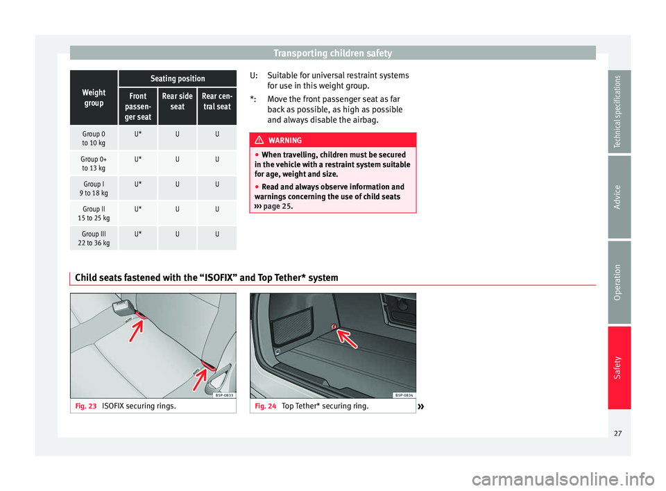
Transporting children safetyWeight
group
Seating position
Front
passen-
ger seatRear side seatRear cen-tral seat
Group 0
to 10 kgU*UU
Group 0+ to 13 kgU*UU
Group I
9 to 18 kgU*UU
Group II
15 to 25 kgU*UU
Group III
22 to 36 kgU*UU Suitable for universal restraint systems
for use in this weight group.
Move the front passenger seat as far
back as possible, as high as possible
and always disable the airbag.
WARNING
● When travelling, children must be secured
in the vehicle with a restraint system suitable
for age, weight and size.
● Read and always observe information and
warnings concerning the use of child seats
››› page 25. U:
*:
Child seats fastened with the “ISOFIX” and Top Tether* system Fig. 23
ISOFIX securing rings. Fig. 24
Top Tether* securing ring.
» 27
Technical specifications
Advice
Operation
Safety
Page 31 of 236
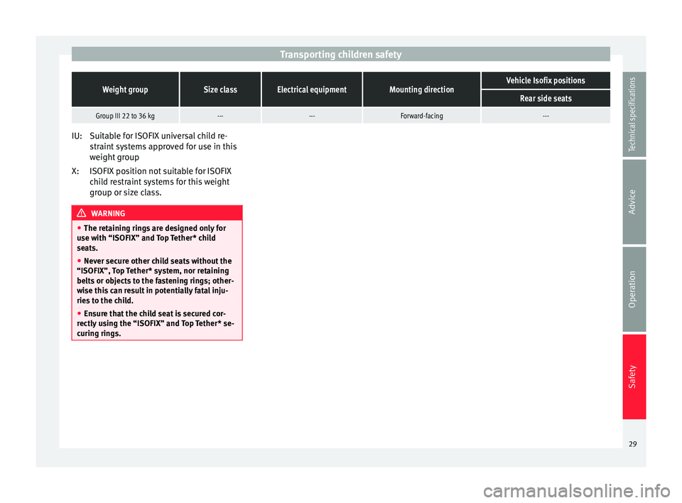
Transporting children safetyWeight groupSize classElectrical equipmentMounting directionVehicle Isofix positions
Rear side seats
Group III 22 to 36 kg------Forward-facing---
Suitable for ISOFIX universal child re-
straint systems approved for use in this
weight group
ISOFIX position not suitable for ISOFIX
child restraint systems for this weight
group or size class.
WARNING
● The retaining rings are designed only for
use with “ISOFIX” and Top Tether* child
seats.
● Never secure other child seats without the
“ISOFIX”, Top Tether* system, nor retaining
belts or objects to the fastening rings; other-
wise this can result in potentially fatal inju-
ries to the child.
● Ensure that the child seat is secured cor-
rectly using the “ISOFIX” and Top Tether* se-
curing rings. IU:
X:
29
Technical specifications
Advice
Operation
Safety
Page 33 of 236
Dash panel
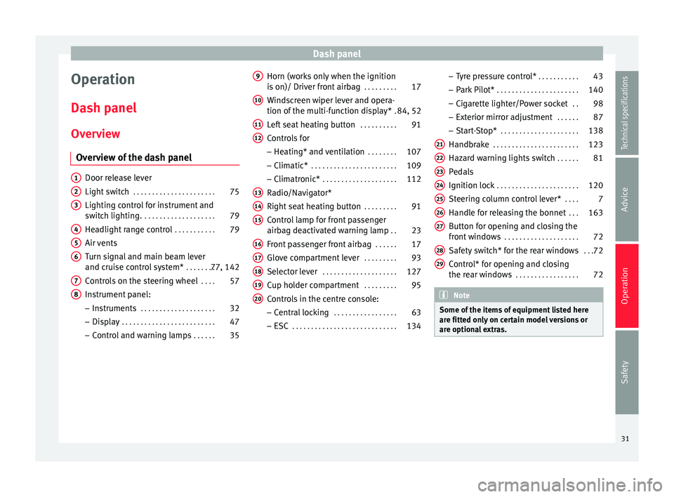
Operation
Dash panel Overview Overview of the dash panel Door release lever
Light switch
. . . . . . . . . . . . . . . . . . . . . . 75
Lighting control for instrument and
switch lighting. . . . . . . . . . . . . . . . . . . . 79
Headlight range control . . . . . . . . . . .79
Air vents
Turn signal and main beam lever
and cruise control system* . . . . . . . .77, 142
Controls on the steering wheel . . . .57
Instrument panel:
– Instruments . . . . . . . . . . . . . . . . . . . . 32
– Display . . . . . . . . . . . . . . . . . . . . . . . . . 47
– Control and warning lamps . . . . . .35
1 2
3
4
5
6
7
8 Horn (works only when the ignition
is on)/ Driver front airbag
. . . . . . . . .17
Windscreen wiper lever and opera-
tion of the multi-function display* .84, 52
Left seat heating button . . . . . . . . . .91
Controls for
– Heating* and ventilation . . . . . . . .107
– Climatic* . . . . . . . . . . . . . . . . . . . . . . . 109
– Climatronic* . . . . . . . . . . . . . . . . . . . . 112
Radio/Navigator*
Right seat heating button . . . . . . . . .91
Control lamp for front passenger
airbag deactivated warning lamp . .23
Front passenger front airbag . . . . . .17
Glove compartment lever . . . . . . . . .93
Selector lever . . . . . . . . . . . . . . . . . . . . 127
Cup holder compartment . . . . . . . . .95
Controls in the centre console: – Central locking . . . . . . . . . . . . . . . . . 63
– ESC . . . . . . . . . . . . . . . . . . . . . . . . . . . . 134
9 10
11
12
13
14
15
16
17
18
19
20 –
Tyre pressure control* . . . . . . . . . . .43
– Park Pilot* . . . . . . . . . . . . . . . . . . . . . . 140
– Cigarette lighter/Power socket . .98
– Exterior mirror adjustment . . . . . .87
– Start-Stop* . . . . . . . . . . . . . . . . . . . . . 138
Handbrake . . . . . . . . . . . . . . . . . . . . . . . 123
Hazard warning lights switch . . . . . .81
Pedals
Ignition lock . . . . . . . . . . . . . . . . . . . . . . 120
Steering column control lever* . . . .7
Handle for releasing the bonnet . . .163
Button for opening and closing the
front windows . . . . . . . . . . . . . . . . . . . . 72
Safety switch* for the rear windows . . .72
Control* for opening and closing
the rear windows . . . . . . . . . . . . . . . . . 72 Note
Some of the items of equipment listed here
are fitted only on certain model versions or
are optional extras. 21
22
23
24
25
26
27
28
29
31Technical specifications
Advice
Operation
Safety
Page 35 of 236
Dash panel
Speedometer The speedometer is equipped with a digital
odometer and a trip odometer, in addition to
a service intervals display.
During the running-in period, the instructions
shown on
››› page 130 should be followed.
F uel
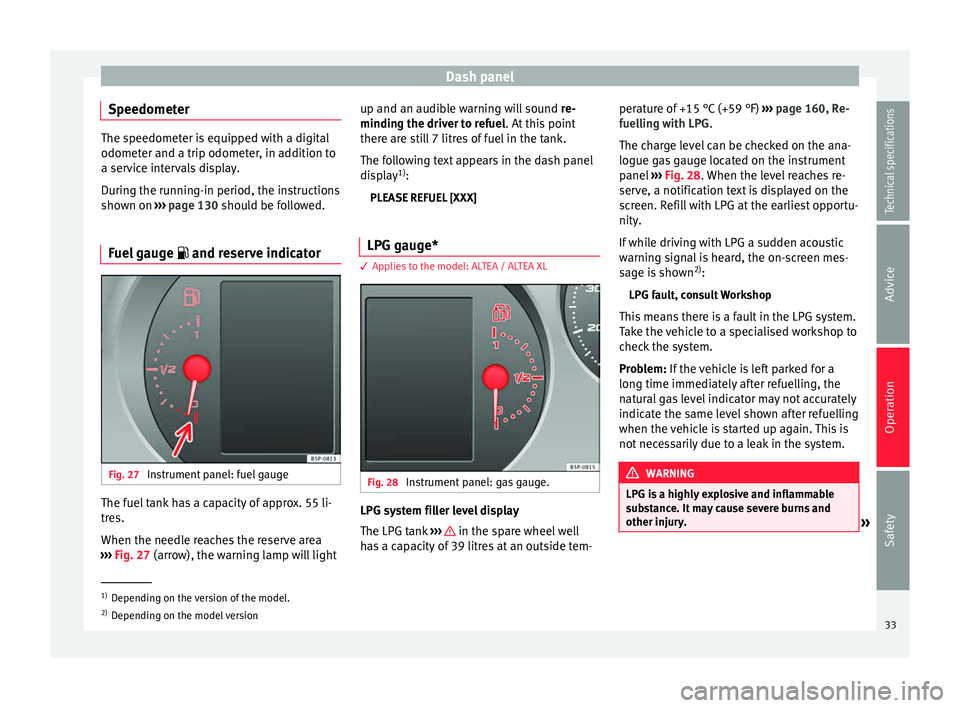
gauge and reserve indicator Fig. 27
Instrument panel: fuel gauge The fuel tank has a capacity of approx. 55 li-
tres.
When the needle reaches the reserve area
››› Fig. 27 (arrow), the warning lamp will light up and an audib
l
e warning will sound
re-
minding the driver to refuel. At this point
there are still 7 litres of fuel in the tank.
The following text appears in the dash panel
display 1)
:
PLEASE REFUEL [XXX]
LPG gauge* 3 Applies to the model: ALTEA / ALTEA XL
Fig. 28
Instrument panel: gas gauge. LPG system filler level display
The LPG tank
››› in the spare wheel well
has a capacity of 39 litres at an outside tem- perature of +15 °C (+59 °F)
››› page 160, Re-
fuelling with LPG .
The c h
arge level can be checked on the ana-
logue gas gauge located on the instrument
panel ››› Fig. 28. When the level reaches re-
serv
e, a notification text is displayed on the
screen. Refill with LPG at the earliest opportu-
nity.
If while driving with LPG a sudden acoustic
warning signal is heard, the on-screen mes-
sage is shown 2)
:
LPG fault, consult Workshop
This means there is a fault in the LPG system.
Take the vehicle to a specialised workshop to
check the system.
Problem: If the vehicle is left parked for a
long time immedi
ately after refuelling, the
natural gas level indicator may not accurately
indicate the same level shown after refuelling
when the vehicle is started up again. This is
not necessarily due to a leak in the system. WARNING
LPG is a highly explosive and inflammable
substance. It may cause severe burns and
other injury. »1)
Depending on the version of the model.
2) Depending on the model version
33
Technical specifications
Advice
Operation
Safety
Page 37 of 236
Dash panel
Setting the digital clock* The digital clock is located in the instrument
panel display.
–
Turn the setting knob ››› Fig. 26
5 clock-
wise until the first “click” to set the hour.
The hour will flash. To change the hour,
press the button. –
Turn the setting knob clockwise to the sec-
ond “click” to set the minutes. The minutes
will flash. To change the minutes, press the
button.
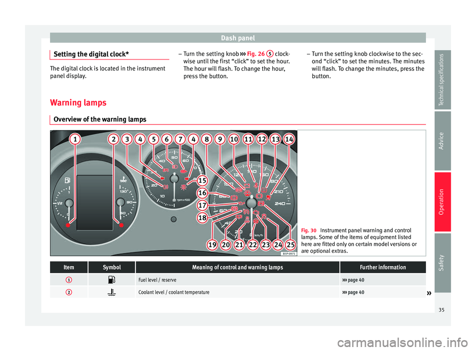
Warning lamps Overview of the warning lamps Fig. 30
Instrument panel warning and control
lamps. Some of the items of equipment listed
here are fitted only on certain model versions or
are optional extras.ItemSymbolMeaning of control and warning lampsFurther information
1 Fuel level / reserve›››
page 40
2 Coolant level / coolant temperature›››
page 40» 35
Technical specifications
Advice
Operation
Safety
Page 39 of 236
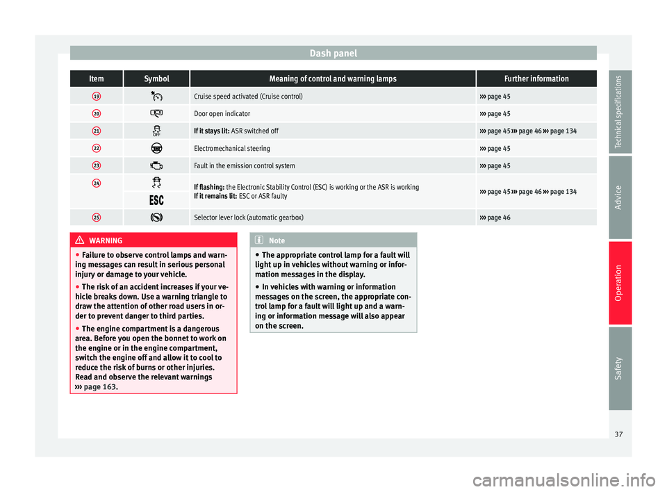
Dash panelItemSymbolMeaning of control and warning lampsFurther information
19
Cruise speed activated (Cruise control)›››
page 45
20 Door open indicator›››
page 45
21 If it stays lit:
ASR switched off››› page 45 ››› page 46 ››› page 134
22 Electromechanical steering›››
page 45
23 Fault in the emission control system›››
page 45
24 If flashing:
the Electronic Stability Control (ESC) is working or the ASR is working
If it remains lit: ESC or ASR faulty››› page 45 ››› page 46 ››› page 134
25
Selector lever lock (automatic gearbox)›››
page 46 WARNING
● Failure to observe control lamps and warn-
ing messages can result in serious personal
injury or damage to your vehicle.
● The risk of an accident increases if your ve-
hicle breaks down. Use a warning triangle to
draw the attention of other road users in or-
der to prevent danger to third parties.
● The engine compartment is a dangerous
area. Before you open the bonnet to work on
the engine or in the engine compartment,
switch the engine off and allow it to cool to
reduce the risk of burns or other injuries.
Read and observe the relevant warnings
››› page 163. Note
● The appropriate control lamp for a fault will
light up in vehicles without warning or infor-
mation messages in the display.
● In vehicles with warning or information
messages on the screen, the appropriate con-
trol lamp for a fault will light up and a warn-
ing or information message will also appear
on the screen. 37
Technical specifications
Advice
Operation
Safety
Page 41 of 236
Dash panel
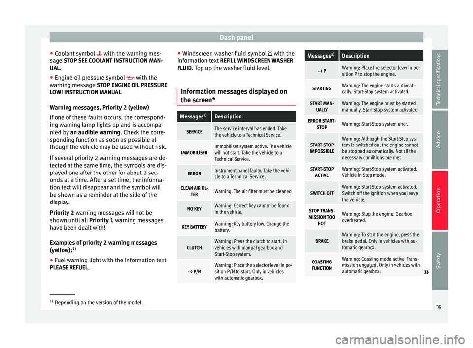
● Coolant symbol with the warning mes-
s ag
e STOP SEE COOLANT INSTRUCTION MAN-
UAL.
● Engine oil pressure symbol with the
warnin
g message STOP ENGINE OIL PRESSURE
LOW! INSTRUCTION MANUAL.
Warning messages, Priority 2 (yellow)
If one of these faults occurs, the correspond-
ing warning lamp lights up and is accompa-
nied by an audible warning. Check the corre-
sponding function as soon as possible al-
though the vehicle may be used without risk.
If several priority 2 warning messages are de-
tected at the same time, the symbols are dis-
played one after the other for about 2 sec-
onds at a time. After a set time, the informa-
tion text will disappear and the symbol will
be shown as a reminder at the side of the
display.
Priority 2 warning messages will not be
shown until all Priority 1 warning messages
have been dealt with!
Examples of priority 2 warning messages
(yellow): 1)
● Fuel warning light with the information text
PLEASE REFUEL . ●
Windscreen washer fluid symbol with the
inform
ation text REFILL WINDSCREEN WASHER
FLUID. Top up the washer fluid level.
Information messages displayed on
the screen*
Messages a)Description
SERVICEThe service interval has ended. Take
the vehicle to a Technical Service.
IMMOBILISERImmobiliser system active. The vehicle
will not start. Take the vehicle to a
Technical Service.
ERRORInstrument panel faulty. Take the vehi-
cle to a Technical Service.
CLEAN AIR FIL-
TERWarning: The air filter must be cleaned
NO KEYWarning: Correct key cannot be found
in the vehicle.
KEY BATTERYWarning: Key battery low. Change the
battery.
CLUTCHWarning: Press the clutch to start. In
vehicles with manual gearbox and
Start-Stop system.
--> P/NWarning: Place the selector level in po-
sition P/N to start. Only in vehicles
with automatic gearbox.
Messages a)Description
--> PWarning: Place the selector lever in po-
sition P to stop the engine.
STARTINGWarning: The engine starts automati-
cally. Start-Stop system activated.
START MAN-
UALLYWarning: The engine must be started
manually. Start-Stop system activated
ERROR START- STOPWarning: Start-Stop system error.
START-STOP
IMPOSSIBLEWarning: Although the Start-Stop sys-
tem is switched on, the engine cannot
be stopped automatically. Not all the
necessary conditions are met
START-STOP ACTIVEWarning: Start-Stop system activated.
Vehicle in Stop mode.
SWITCH OFFWarning: Start-Stop system activated.
Switch off the ignition when you leave
the vehicle.
STOP TRANS-
MISSION TOO HOTWarning: Stop the engine. Gearbox
overheated.
BRAKEWarning: To start the engine, press the
brake pedal. Only in vehicles with au-
tomatic gearbox.
COASTINGFUNCTIONWarning: Coasting mode active. Trans-
mission engaged. Only in vehicles with
automatic gearbox.
» 1)
Depending on the version of the model.
39
Technical specifications
Advice
Operation
Safety
Page 43 of 236
Dash panel
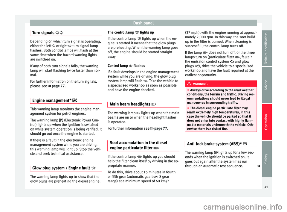
Turn signals
Depending on which turn signal is operating,
either the left
or right turn signal lamp
fl a
shes. Both control lamps will flash at the
same time when the hazard warning lights
are switched on.
If any of both turn signals fails, the warning
lamp will start flashing twice faster than nor-
mal.
For further information on the turn signals,
please see ››› page 77.
Engine management* This warning lamp monitors the engine man-
agement system for petrol engines.
The warning lamp (Electronic Power Con-
trol) lights up when the ignition is switched
on while system operation is being verified. It
should go out once the engine is started.
If there is a fault in the electronic engine
management system while you are driving,
this warning lamp will light up. Stop the vehi-
cle and seek technical assistance.
Glow plug system / Engine fault The warning lamp lights up to show that the
glow plugs are preheating the diesel engine. The control lamp
lights up
If the c
ontrol lamp lights up when the en-
gine is
started it means that the glow plugs
are preheating. When the warning lamp goes
off, the engine should be started straight
away.
Control lamp flashes
If a f
ault develops in the engine management
system while you are driving, the glow plug
system lamp will flash
. Take the vehicle to
a specialised workshop as soon as possible
and have the engine checked.
Main beam headlights The warning lamp lights up when the main
beams are on or when the headlight flasher
is operated.
For further information see
›››
page 77.
Soot accumulation in the diesel
engine particulate filter If the control lamp
lights up you should
help the filter clean itself by driving in the ap-
propriate manner.
To do this, drive about 15 minutes in fourth
or fifth gear (automatic gearbox: S gear
range) at a minimum speed of 60 km/h (37 mph), with the engine running at approxi-
mately 2,000 rpm. In this way, the soot build
up in the filter is burned. When cleaning is
successful, the control lamp turns off.
If the lamp
does not turn off, or the three
l amp
s turn on (particulate filter , fault in
the emission control system and glow
plugs ), drive the vehicle to a specialised
workshop and have the fault repaired at the
earliest opportunity. WARNING
● Always drive according to the road weather
conditions, the terrain and traffic. Driving rec-
ommendations should never lead to illegal
manoeuvres in surrounding traffic.
● The diesel engine particulate filter may
reach extremely high temperatures; in this
case the vehicle should be parked so that it
does not enter into contact with highly flam-
mable materials underneath the vehicle. Oth-
erwise there is a risk of fire. Anti-lock brake system (ABS)*
The warning lamp lights up for a few sec-
onds when the ignition is switched on. It
goes out again after the system has run
through an automatic test sequence.
»
41Technical specifications
Advice
Operation
Safety