Seat Altea XL 2015 Owner's Manual
Manufacturer: SEAT, Model Year: 2015, Model line: Altea XL, Model: Seat Altea XL 2015Pages: 236, PDF Size: 4.23 MB
Page 191 of 236
Emergencies
● If the indicated pressure still cannot be
reached, the tyre is too badly damaged. The
tyre cannot be sealed with the anti-puncture
kit. Do not continue driving. You should ob-
tain professional assistance ››› .
● Disconnect the air compressor and unscrew
the flexible inflator tube from the tyre valve.
● When the tyre pressure is between 2.5 and
2.0 bars, immediately continue driving with-
out exceeding 80 km/h (50 mph).
● After 10 minutes
, Check the pressure again
›
›› page 189. WARNING
When inflating the wheel, the air compressor
and the inflator tube may become hot.
● Protect hands and skin from hot parts.
● Do not place the hot flexible inflator tube or
hot air compressor on flammable material.
● Allow them to cool before storing the de-
vice.
● If it is not possible to inflate the tyre to at
least 2.0 bars (29 psi / 200 kPa), the tyre is
too badly damaged. The sealant is not in a
good condition to seal the tyre. Do not con-
tinue driving. Seek specialist assistance. CAUTION
Switch off the air compressor after a maxi-
mum of 8 operational minutes to prevent it
from overheating! Before switching on the air compressor again, let it cool for several mi-
nutes.
Check after 10 minutes of driving
Screw the inflator tube
››› Fig. 162 5 again
and check the pressure on the gauge 6 .
1.3 bar (19 psi / 130 kPa) and lower:
● Stop the vehicle! The tyre cannot be sealed
sufficiently with the tyre mobility set.
● You should obtain professional assistance
››› .
1.4 bar (20 psi / 140 kPa) and higher:
● Set the tyre pressure to the correct value
again.
● Carefully resume your journey until you
reach the nearest specialised workshop with-
out exceeding 80 km/h (50 mph).
● Have the damaged tyre replaced. WARNING
Driving with an unsealed tyre is dangerous
and can cause accidents and serious injury.
● Do not continue driving if the tyre pressure
is 1.3 bar (19 psi / 130 kPa) and lower.
● Seek specialist assistance. Jump-starting
Jump leads The jump lead must have a sufficient wire
cross section.
If the engine fails to start because of a dis-
charged battery, the battery can be connec-
ted to the battery of another vehicle to start
the engine.
Jump leads
Jump leads must comply with standard
DIN
72553 (see cable manufacturer's instruc-
tion s).
The wire cross section must be at least
25 mm 2
for petrol engines and at least
35 mm 2
for diesel engines. Note
● The vehicles must not touch each other,
otherwise electricity could flow as soon as
the positive terminals are connected.
● The discharged battery must be properly
connected to the on-board network. 189
Technical specifications
Advice
Operation
Safety
Page 192 of 236
Advice
How to jump start: description Fig. 163
Diagram of connections for vehicles
without Start-Stop system. Fig. 164
Diagram of connections for vehicles
with Start-Stop system. Jump lead terminal connections
1. Switch off the ignition of both vehicles
››› . 2. Connect one end of the
red jump lead to
the po s
itive + terminal of the vehicle
with the flat battery A
››› Fig. 163 .
3. C
onnect the other end of the red
jump
lead to the positive terminal + in the ve-
hicle providing assistance B .
4. For vehicles without Start-Stop system:
connect one end of the black jump lead to
the negative terminal – in the vehicle
providing assistance B
››› Fig. 163 .
– For
vehicles with Start-Stop system: Con-
nect one end of the black jump lead X to a
suitable ground terminal, a solid piece of
metal in the engine block, or to the engine
block itself ››› Fig. 164.
5. Connect the other end of the black jump
lead X to a solid metal component bolted
to the engine block or to the engine block
itself of the vehicle with the flat battery.
Do not connect it to a point near the bat-
tery A .
6. Position the leads in such a way that they cannot come into contact with any moving
parts in the engine compartment.
Starting
7. Start the vehicle's engine with the boost- ing battery and let it run at idling speed.
8. Start the engine of the vehicle with the flat battery and wait 2 or 3 minutes until the
engine is “running”. Removing the jump leads
9. Before you remove the jump leads, switch
off the dipped beam headlights (if they
are switched on).
10.Turn on the heater blower and heated rear window in the vehicle with the flat battery.
This helps minimise voltage peaks which
are generated when the leads are discon-
nected.
11. When the engine is running, disconnect
the l e
ads in reverse order to the details
given above.
Connect the battery clamps so they have
good metal-to-metal contact with the battery
terminals.
If the engine fails to start, switch off the start-
er after about 10 seconds and try again after
about a minute. WARNING
● Please note the safety warnings referring to
working in the engine compartment
››› page 163, Working in the engine compart-
ment.
● The b att
ery providing assistance must have
the same voltage as the flat battery (12 V)
and approximately the same capacity (see
imprint on battery). Failure to comply could
result in an explosion.
● Never use jump leads when one of the bat-
teries is frozen. Danger of explosion! Even 190
Page 193 of 236
Emergencies
after the battery has thawed, battery acid
could leak and cause chemical burns. If a bat-
tery freezes, it should be replaced.
●
Keep sparks, flames and lighted cigarettes
away from batteries, danger of explosion.
Failure to comply could result in an explo-
sion.
● Observe the instructions provided by the
manufacturer of the jump leads.
● Do not connect the negative cable from the
other vehicle directly to the negative terminal
of the flat battery. The gas emitted from the
battery could be ignited by sparks. Danger of
explosion.
● Do not attach the negative cable from the
other vehicle to parts of the fuel system or to
the brake line.
● The non-insulated parts of the battery
clamps must not be allowed to touch. The
jump lead attached to the positive battery
terminal must not touch metal parts of the ve-
hicle, this can cause a short circuit.
● Position the leads in such a way that they
cannot come into contact with any moving
parts in the engine compartment.
● Do not lean on the batteries. This could re-
sult in chemical burns. Note
The vehicles must not touch each other, oth-
erwise electricity could flow as soon as the
positive terminals are connected. Towing and tow-starting
Tow-starting We recommend that you do
not tow-start your
v ehic
le. Jump-starting is preferable
››› page 189.
How
ever, if your vehicle has to be tow-
started:
– Engage 2 nd
or 3 rd
gear.
– Keep the clutch pressed down.
– Switch the ignition on.
– Once both vehicles are moving, release the
clutch.
– As soon as the engine starts, press the
clutch and move the gear lever into neutral.
This helps to prevent driving into the tow-
ing vehicle. WARNING
The risk of accidents is high when tow-start-
ing. The vehicle being towed can easily col-
lide with the towing vehicle. CAUTION
When tow-starting, fuel could enter the cata-
lytic converter and damage it. General notes
Please observe the following points if you
use a tow rope:
Notes for the driver of the towing vehicle
– Drive slowly at first until the tow rope is
taut. Then accelerate gradually.
– Begin and change gears cautiously. If you
are driving an automatic vehicle, accelerate
gently.
– Remember that the brake servo and power
steering are not working in the vehicle you
are towing. Brake sooner than normal and
pressing the pedal gently.
Notes for the driver of the towed vehicle
– Ensure that the tow rope remains taut at all
times when towing.
Tow rope or tow bar
It is easier and safer for the vehicle to be tow-
ed using a tow bar. You should only use a
tow-rope if you do not have a tow-bar.
A tow rope should be slightly elastic to re-
duce the loading on both vehicles. It is advis-
able to use a tow rope made of synthetic fi-
bre or similarly elastic material.
Attach the tow rope or the tow bar only to the
towline anchorages provided or a towing
bracket. »
191Technical specifications
Advice
Operation
Safety
Page 194 of 236
Advice
Driving style
Towing requires some experience, especially
when using a tow rope. Both drivers should
be familiar with the technique required for
towing. Inexperienced drivers should not at-
tempt to tow.
Do not pull too hard with the towing vehicle
and take care to avoid jerking the tow rope.
When towing on an unpaved road, there is al-
ways a risk of overloading and damaging the
anchorage points.
The ignition of the vehicle being towed must
be switched on to prevent the steering wheel
from locking and also to allow the use of the
turn signals, horn, windscreen wipers and
washers.
The brake servo only works when the engine
is running. When not running, you must ap-
ply considerably more pressure to the brake
pedal.
As the power assisted steering does not work
if the engine is not running, you will need
more strength to steer than you normally
would.
● The vehicle must not be towed faster than
50 km/h (31 mph).
Towing vehicles with an automatic gearbox
● Put the selector lever into position “N”.
● Do not drive faster than 50 km/h (31 mph). ●
Do not tow further than 50 km.
● If a breakdown vehicle is used, the vehicle
must be towed with the front wheels raised. Note
● Observe legal requirements when towing or
tow-starting.
● Switch on the hazard warning lights of both
vehicles. However, observe any regulations
to the contrary.
● For technical reasons, vehicles with an au-
tomatic gearbox must not be tow-started.
● If there is no lubricant in the gearbox as the
result of a fault, you must raise the driven
wheels while the vehicle is being towed.
● If the vehicle has to be towed more than
50 km, the front wheels should be raised dur-
ing towing, and towing should be carried out
by a qualified person.
● The steering wheel is locked when the vehi-
cle has no electrical power. The vehicle must
then be towed with the front wheels raised.
Towing should be carried out by a qualified
person.
● The towline anchorage should always be
kept in the vehicle. Please refer to the notes
on ››› page 191, Tow-starting. Towline anchorages
Fig. 165
Fitting the front towline anchorage
to the front right section of the vehicle. Fig. 166
Fitting the towline anchorage to the
rear of the vehicle. Front towline anchorage
– Take the towline anchorage from the on-
board tool set.
– Remove the cover by pressing down on its
left-hand side.
192
Page 195 of 236
Emergencies
– Bolt the anchorage to its limit to the left, in
the dir ection of
the arrow ››› Fig. 165.
Re
ar towline anchorage
– Take the towline anchorage from the on-
board tool set.
– Remove the cover by pressing down on its
right-hand side.
– Bolt the anchorage to its limit to the left
, in
the direction of the arrow ››› Fig. 166.
Aft
er use, unscrew the towline anchorage
and put it back in the vehicle tool kit. Replace
the cover on the bumper. The towline anchor-
age should always be kept in the vehicle. Emergency locking and
unlocking
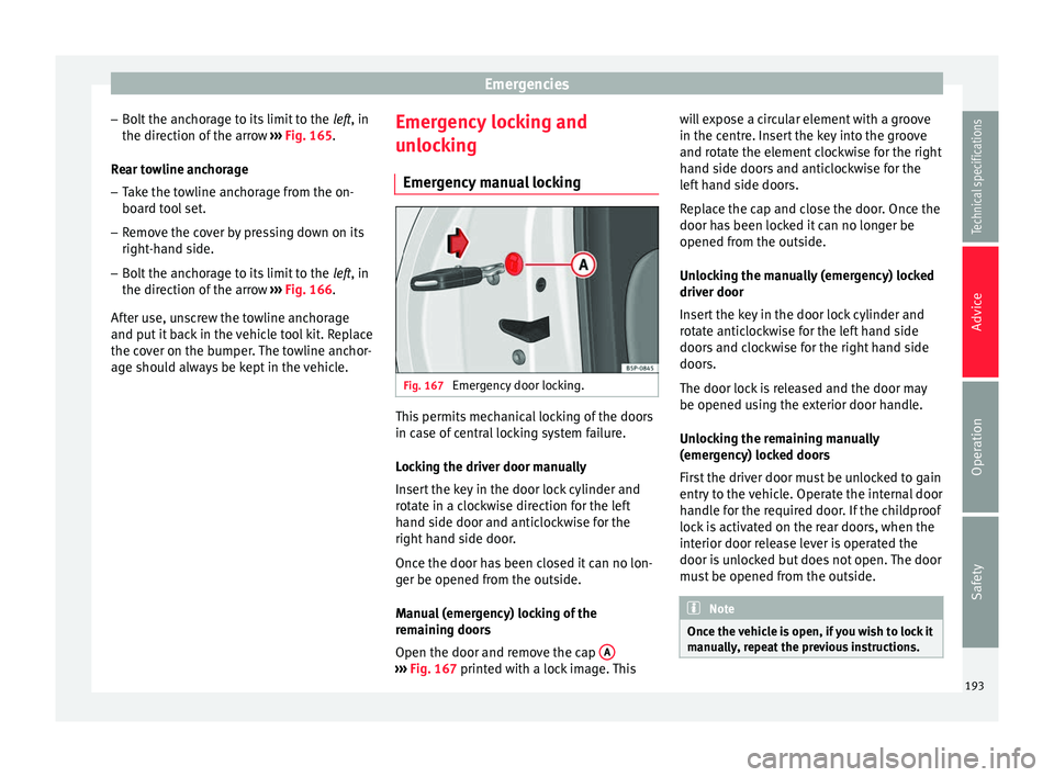
Emergency manual locking Fig. 167
Emergency door locking. This permits mechanical locking of the doors
in case of central locking system failure.
Locking the driver door manually
Insert the key in the door lock cylinder and
rotate in a clockwise direction for the left
hand side door and anticlockwise for the
right hand side door.
Once the door has been closed it can no lon-
ger be opened from the outside.
Manual (emergency) locking of the
remaining doors
Open the door and remove the cap
A ›››
Fig. 167 printed with a lock image. This w
i
ll expose a circular element with a groove
in the centre. Insert the key into the groove
and rotate the element clockwise for the right
hand side doors and anticlockwise for the
left hand side doors.
Replace the cap and close the door. Once the
door has been locked it can no longer be
opened from the outside.
Unlocking the manually (emergency) locked
driver door
Insert the key in the door lock cylinder and
rotate anticlockwise for the left hand side
doors and clockwise for the right hand side
doors.
The door lock is released and the door may
be opened using the exterior door handle.
Unlocking the remaining manually
(emergency) locked doors
First the driver door must be unlocked to gain
entry to the vehicle. Operate the internal door
handle for the required door. If the childproof
lock is activated on the rear doors, when the
interior door release lever is operated the
door is unlocked but does not open. The door
must be opened from the outside. Note
Once the vehicle is open, if you wish to lock it
manually, repeat the previous instructions. 193
Technical specifications
Advice
Operation
Safety
Page 196 of 236
Advice
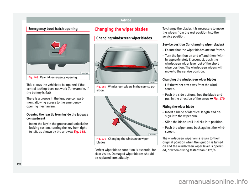
Emergency boot hatch opening Fig. 168
Rear lid: emergency opening. This allows the vehicle to be opened if the
central locking does not work (for example, if
the battery is flat)
There is a groove in the luggage compart-
ment allowing access to the emergency
opening mechanism.
Opening the rear lid from inside the luggage
compartment
– Insert the key in the groove and unlock the
locking system, turning the key from right
to left, as shown by the arrow ››› Fig. 168 .Ch
an ging the wiper blades
Changing windscreen wiper blades Fig. 169
Windscreen wipers in the service po-
sition. Fig. 170
Changing the windscreen wiper
blades Perfect wiper blade condition is essential for
clear vision. Damaged wiper blades should
be replaced immediately.To change the blades it is necessary to move
the wipers from the rest position into the
service position.
Service position (for changing wiper blades)
–
Ensure that the wiper blades are not frozen.
– Turn the ignition on and off and then (with-
in approximately 8 seconds), push the
windscreen wiper lever out of the short
wipe position. The windscreen wipers will
move to the service position.
Changing the windscreen wiper blades – Lift the wiper arm away from the wind-
screen.
– Push the side buttons, free the blade and
pull in the direction of the arrow ››› Fig. 170
Fitting the wiper blade
– Insert a blade of identical length and de-
sign into the wiper arm.
– Slide the blade until it clicks into position.
– Push the wiper arms back against the wind-
screen.
The windscreen wiper arms return to their
original position when the ignition is turned
on and the windscreen wiper lever is operat-
ed, or when driving faster than 6 km/h.
194
Page 197 of 236
Emergencies
If the windscreen wipers scratch , they should
be replaced if they are damaged, or cleaned
if they are soiled.
If this does not produce the desired results,
the setting angle of the windscreen wiper
arms might be incorrect. They should be
checked by a specialised workshop and cor-
rected if necessary. WARNING
Do not drive unless you have good visibility
through all windows!
● Clean the windscreen wiper blades and all
windows regularly.
● The wiper blades should be changed once
or twice a year. CAUTION
● Damaged or dirty windscreen wipers could
scratch the windscreen.
● Never use fuel, nail varnish remover, paint
thinner or similar products to clean the win-
dows. This could damage the windscreen
wiper blades.
● Never move the windscreen wiper or wind-
screen wiper arm manually. This could cause
damage.
● To prevent damage to the bonnet and the
windscreen wiper arms, the latter should only
be lifted off the windscreen when in service
position. Note
● The windscreen wiper arms can be moved
to the service position only when the bonnet
is properly closed. Changing the rear wiper blade
3 Applies to the model: ALTEA
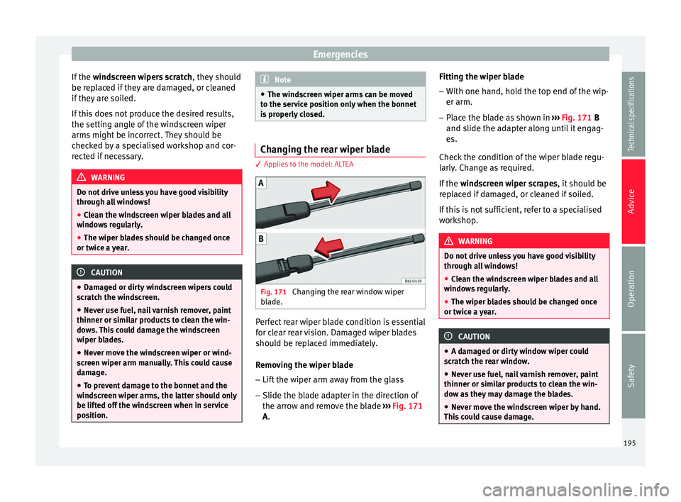
Fig. 171
Changing the rear window wiper
blade. Perfect rear wiper blade condition is essential
for clear rear vision. Damaged wiper blades
should be replaced immediately.
Removing the wiper blade
– Lift the wiper arm away from the glass
– Slide the blade adapter in the direction of
the arrow and remove the blade ››› Fig. 171
A . Fittin
g the w iper blade
– With one hand, hold the top end of the wip-
er arm.
– Place the blade as shown in ››› Fig. 171
B
and slide the adapter along until it engag-
es.
Check the condition of the wiper blade regu-
larly. Change as required.
If the windscreen wiper scrapes, it should be
replaced if damaged, or cleaned if soiled.
If this is not sufficient, refer to a specialised
workshop. WARNING
Do not drive unless you have good visibility
through all windows!
● Clean the windscreen wiper blades and all
windows regularly.
● The wiper blades should be changed once
or twice a year. CAUTION
● A damaged or dirty window wiper could
scratch the rear window.
● Never use fuel, nail varnish remover, paint
thinner or similar products to clean the win-
dow as they may damage the blades.
● Never move the windscreen wiper by hand.
This could cause damage. 195
Technical specifications
Advice
Operation
Safety
Page 198 of 236
Advice
Changing the rear wiper blade 3 Applies to the model: ALTEA XL/ALTEA FREETRACK
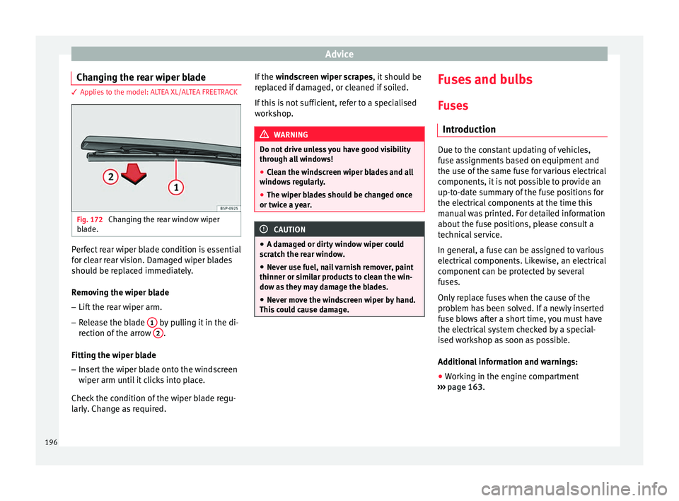
Fig. 172
Changing the rear window wiper
blade. Perfect rear wiper blade condition is essential
for clear rear vision. Damaged wiper blades
should be replaced immediately.
Removing the wiper blade
– Lift the rear wiper arm.
– Release the blade 1 by pulling it in the di-
rection of the arrow 2 .
Fitting the wiper blade – Insert the wiper blade onto the windscreen
wiper arm until it clicks into place.
Check the condition of the wiper blade regu-
larly. Change as required. If the
windscreen wiper scrapes, it should be
replaced if damaged, or cleaned if soiled.
If this is not sufficient, refer to a specialised
workshop. WARNING
Do not drive unless you have good visibility
through all windows!
● Clean the windscreen wiper blades and all
windows regularly.
● The wiper blades should be changed once
or twice a year. CAUTION
● A damaged or dirty window wiper could
scratch the rear window.
● Never use fuel, nail varnish remover, paint
thinner or similar products to clean the win-
dow as they may damage the blades.
● Never move the windscreen wiper by hand.
This could cause damage. Fuses and bulbs
Fuses Introduction Due to the constant updating of vehicles,
fuse assignments based on equipment and
the use of the same fuse for various electrical
components, it is not possible to provide an
up-to-date summary of the fuse positions for
the electrical components at the time this
manual was printed. For detailed information
about the fuse positions, please consult a
technical service.
In general, a fuse can be assigned to various
electrical components. Likewise, an electrical
component can be protected by several
fuses.
Only replace fuses when the cause of the
problem has been solved. If a newly inserted
fuse blows after a short time, you must have
the electrical system checked by a special-
ised workshop as soon as possible.
Additional information and warnings:
● Working in the engine compartment
››› page 163 .
196
Page 199 of 236
Fuses and bulbs
WARNING
The high voltages in the electrical system can
give serious electrical shocks, causing burns
and even death!
● Never touch the electrical wiring of the igni-
tion system.
● Take care not to cause short circuits in the
electrical system. WARNING
Using unsuitable fuses, repairing fuses or
bridging a current circuit without fuses can
cause a fire and serious injury.
● Never use a fuse with a higher value. Only
replace fuses with a fuse of the same amper-
age (same colour and markings) and size.
● Never repair a fuse.
● Never replace a fuse by a metal strip, staple
or similar. CAUTION
● To prevent damage to the vehicle's electric
system, before replacing a fuse turn off the
ignition, the lights and all electrical elements
and remove the key from the ignition.
● If you replace a fuse with higher-rating
fuse, you could cause damage to another part
of the electrical system.
● Protect the fuse boxes when open to pre-
vent the entry of dust or humidity as they can
damage the electrical system. Note
● One component may have more than one
fuse.
● Several components may run on a single
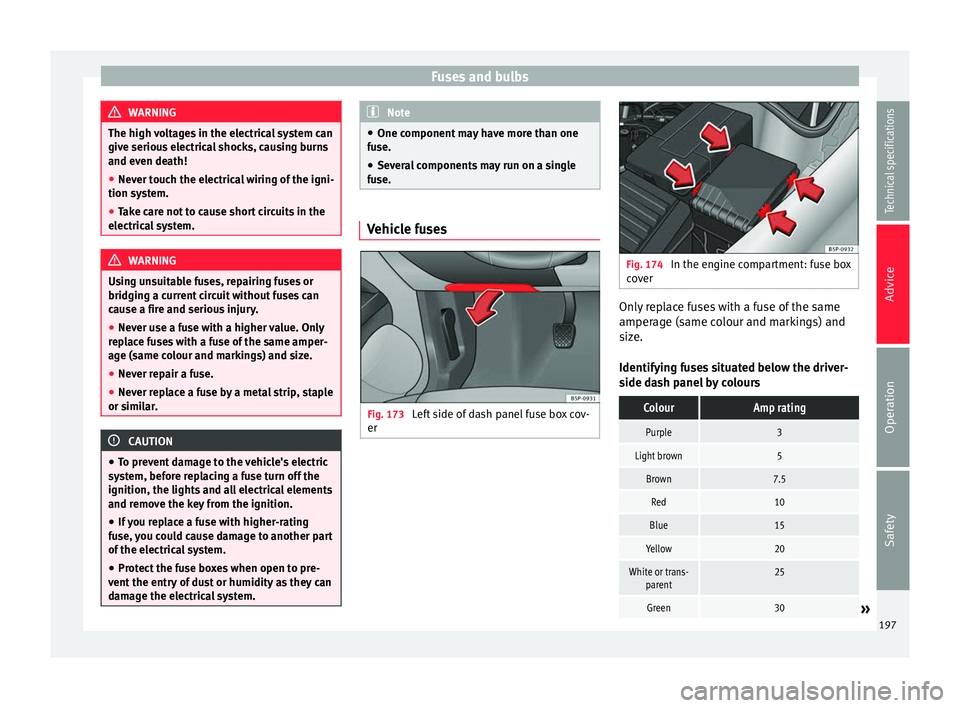
fuse. Vehicle fuses
Fig. 173
Left side of dash panel fuse box cov-
er Fig. 174
In the engine compartment: fuse box
cover Only replace fuses with a fuse of the same
amperage (same colour and markings) and
size.
Identifying fuses situated below the driver-
side dash panel by coloursColourAmp rating
Purple3
Light brown5
Brown7.5
Red10
Blue15
Yellow20
White or trans-
parent25
Green30» 197
Technical specifications
Advice
Operation
Safety
Page 200 of 236
AdviceColourAmp rating
Orange40
Opening and closing the fuse box situated
below the dash panel
●
Opening: fold the cover down ››
› Fig. 173.
● Closing:
push back the cover it in until it
clicks into place.
To open the engine compartment fuse box
● Open the bonnet ›››
page 163.
● Press the locking tabs in the direction indi-
cated by the arrows to release the fuse box
cover ›››
Fig. 174.
● Then lif t
the cover out.
● To
fit the cover, place it on the fuse box.
Push the locking tabs down, in the opposite
direction to that indicated by the arrows, un-
til you hear them click into place. CAUTION
● Always carefully remove the fuse box cov-
ers and refit them correctly to avoid problems
with your vehicle.
● Protect the fuse boxes when open to avoid
the entry of dust or humidity. Dirt and humid-
ity inside fuse boxes can cause damage to
the electrical system. Note
In the vehicle, there are more fuses than
those indicated in this chapter. These should
only be changed by a specialised workshop. Replacing a blown fuse
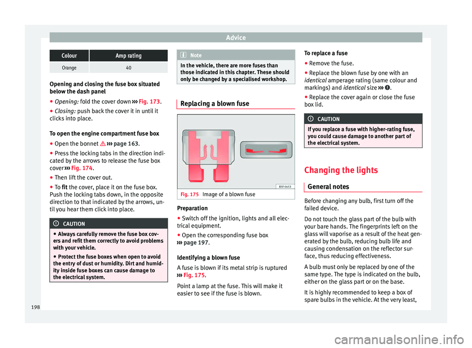
Fig. 175
Image of a blown fuse Preparation
● Switch off the ignition, lights and all elec-
trical equipment.
● Open the corresponding fuse box
››› page 197 .
Identif y
ing a blown fuse
A fuse is blown if its metal strip is ruptured
››› Fig. 175
.
Point a lamp at the fuse. This will make it
easier to see if the fuse is blown. To replace a fuse
● Remove the fuse.
● Replace the blown fuse by one with an
identical amperage rating (same colour and
mark
ings) and identical size ››› .
● Replace the cover again or close the fuse
box lid. CAUTION
If you replace a fuse with higher-rating fuse,
you could cause damage to another part of
the electrical system. Changing the lights
General notes Before changing any bulb, first turn off the
failed device.
Do not touch the glass part of the bulb with
your bare hands. The fingerprints left on the
glass will vaporise as a result of the heat gen-
erated by the bulb, reducing bulb life and
causing condensation on the reflector sur-
face, thus reducing effectiveness.
A bulb must only be replaced by one of the
same type. The type is indicated on the bulb,
either on the glass part or on the base.
It is highly recommended to keep a box of
spare bulbs in the vehicle. At the very least,
198