ignition Seat Arona 2018 Manual Online
[x] Cancel search | Manufacturer: SEAT, Model Year: 2018, Model line: Arona, Model: Seat Arona 2018Pages: 316, PDF Size: 6.77 MB
Page 216 of 316

Operation
Switching the Front Assist off tempo-
r ari
ly
in the following situations In the following situations the Front Assist
shoul
d be de
activated due to the system's
limitations:
● When the vehicle is to be towed.
● If the vehicle is on a test bed.
● When the radar sensor is damaged.
● If the radar sensor takes a heavy knock, for
examp
le in a rear collision.
● If it intervenes several times unnecessarily.
● If the radar sensor is covered temporarily
with some k ind of
accessory, such as an ad-
ditional headlight or the like.
● When the vehicle is to be loaded on a lorry,
ferry
or train.
System limitations The Front Assist has certain physical limita-
tion
s
inher
ent to the system. Thus, in certain
circumstances, some of the system's reac-
tions may be inopportune from the driver's
standpoint. So pay attention in order to inter-
vene if necessary. The following conditions may cause the Front
Assi
st not to react or to do so too late:
● In the first few instants of driving after
switc
hing on the ignition, due to the system’s
initial auto-calibration.
● On taking tight bends or complex paths.
● Pressing the accelerator all the way down.
● If the Front Assist is switched off or dam-
aged.
● If the ASR h
as been disconnected or the
ESC activ
ated in Sport mode manually
››› page 183.
● If the ESC is controlling.
● If several brake lights of the vehicle or elec-
trically
connected trailer are damaged.
● If the radar sensor is dirty or covered.
● If there are metal objects, e.g. rails on the
roa
d or sheets used in road works.
● If the vehicle is reversing.
● If the vehicle over-accelerates.
● In case of snow or heavy rain.
● In case of narrow vehicles, such as motor-
bike
s.
● Misaligned vehicles.
● Vehicles crossing the other's path.
● Vehicles approaching in the opposite direc-
tion. ●
Speci
al loads and accessories of other ve-
hicles that jut out over the sides, backwards
or over the top.
Adaptive Cruise Control ACC* Relat
ed video Fig. 192
Safety Introduction
Fig. 193
Detection area.214
Page 218 of 316

Operation
●
When the AC C
is switched on, strange
noises may be heard during automatic
braking cause by the braking system. Indications on the display, warning
and contr
o
l lampsFig. 194
On the instrument panel display: (A)
A C
C
inactive (Standby). (B) ACC active. Status display
Indic
ation
s
on the display ›››
Fig. 194: Vehicle ahead detected. ACC is not active
and is not
regulating your speed.
Distance from the vehicle ahead. ACC is
not active and is not regulating your dis-
tance.
Vehicle ahead detected. ACC is active and
is regulating your speed.
Distance level 2 set by the driver.
ACC is active and is regulating your dis-
tance based on speed.
Symbols on the instrument panel display
and control lamps.
››› in Warning symbols on page 122.
The speed reduction by the ACC to
maintain the distance from the vehi-
cle in front is not sufficient.
Brake! apply the foot brake! Driver intervention prompt.
The ACC is not currently available.
a)
With the vehicle stationary, switch off the engine and
start it up again. Check the radar sensor visually
››› Fig. 195 (for dirt, ice or knocks). If it is still unavaila-
ble, refer to a specialised workshop to have the system
inspected.
a) The symbol on the instrument panels with colour display is in
colour.
1 2
3
4
5 The ACC is active.
No vehicle is detected in front. The programmed speed
remains constant.
If the symbol is white: the ACC is ac-
tive.
A vehicle in front has been detected. The ACC adjusts
speed and distance from the vehicle in front.
If the symbol is grey: ACC is inactive
(Standby)
The system is switched on, but is not adjusting.
It lights up green:
The ACC is active.
Some warning and control lamps will light up
briefly
when the ignition i
s
switched on to
check certain functions. They will switch off
after a few seconds. WARNING
Observe the safety warnings ›››
in Warning
symbol s on p
age 122. Note
When the ACC is connected, the indications
on the ins trument
panel screen may be con-
cealed by warnings from other functions,
such as an incoming call. 216
Page 222 of 316
.
ACC: engine speed
The message for the driver is displayed if,
when the ACC accelerates or brakes, the driv-
er does not shi")
Operation
The ACC is operational as of the 2nd gear
(m anual
g
earbox).
ACC: engine speed
The message for the driver is displayed if,
when the ACC accelerates or brakes, the driv-
er does not shift up or down a gear in time,
which means exceeding or not reaching the
permissible engine speed. The ACC switches
itself off. A buzzer warning is heard. ACC: clutch pressed
Vehicles with a manual gearbox: pressing the
clutch pedal for longer abandons control
mode. Door open
Vehicles with automatic gearbox: the ACC
cannot be activated with the vehicle station-
ary and the door open. WARNING
There is a danger of rear collision when the
minimum dis t
ance to the vehicle in front is
exceeded and the speed difference between
both vehicles is so great that a speed reduc-
tion by the ACC will not suffice. In this case
the brake pedal should be applied immedi-
ately.
● The ACC may not be able to detect all situa-
tions pr
operly.
● “Stepping” on the accelerator may cause
the ACC
not to intervene in braking. Driver braking will have priority over intervention by
the speed c
ontr
ol or adaptive cruise control.
● Always be ready to use the brakes!
● Observe country-specific provisions gov-
erning ob
ligatory minimum distances be-
tween vehicles.
● It is dangerous to activate control and re-
sume the progr
ammed speed if the road, traf-
fic or weather conditions do not permit this.
Risk of accident! Note
● The pr ogrammed s
peed is erased once the
ignition or the ACC are switched off.
● When the traction control system (ASR) is
deactivat
ed during acceleration or else the
ESC is activated in Sport* Mode
( ››› page 122), the ACC switches off automati-
cally.
● In vehicles with the Start-Stop system, the
engine swit
ches off automatically during the
ACC stopping phase and restarts automatical-
ly to begin driving. Function for preventing overtaking in
an in
s
ide l
ane Fig. 198
On the instrument panel display:
A C
C
active, vehicle detected in an outer lane. The adaptive cruise control (ACC) has a func-
tion th
at
help
s avoid overtaking while driving
in inside lanes at certain speeds.
If another vehicle is detected travelling at a
slower speed in an outer lane, it is displayed
on the multifunction display ››› Fig. 198.
To avoid overtaking while driving in an inside
lane the system will gently brake, and in ac-
cordance with the speed will prevent the car
from overtaking. The driver can override this
function at any time by pressing the accelera-
tor pedal. At low speeds the function is inac-
tive, for greater comfort in a traffic jam or in
city traffic.
220
Page 226 of 316
 with
p ark
in
g assistance (RCTA)*
Introduction The blind spot detector (BSD) helps to detect
the traffic
s
ituation behind the vehicle.
The integrated parking as")
Operation
Blind spot detector (BSD) with
p ark
in
g assistance (RCTA)*
Introduction The blind spot detector (BSD) helps to detect
the traffic
s
ituation behind the vehicle.
The integrated parking assistant (RCTA) helps
the driver when backing out of a parallel
parking spot and in manoeuvring.
The blind spot detector has been developed
for driving on paved roads. WARNING
The smart technology incorporated into the
blind s pot
detector (BSD) with parking assis-
tance (RCTA) included cannot overcome the
limits imposed by the laws of physics; it only
works within the limits of the system. Acci-
dents and severe injury may occur if the blind
spot detection system or the rear cross traffic
alert are used negligently or involuntarily.
The system is not a replacement for driver
awareness.
● Adapt your speed and safe distance to the
vehicl
e in front of you at all times to suit visi-
bility, weather, road and traffic conditions.
● Keep your hands on the wheel at all times
to be re
ady to intervene in the steering at any
time.
● Pay attention to the control lamps that may
come on in the ext
ernal rear view mirrors and on the instrument panel, and follow any in-
struction
s
they may give.
● The blind spot assistant could react to any
speci
al constructions that might be present
on the sides of the vehicle: e.g. high or irreg-
ular dividers. This may cause erroneous warn-
ings.
● Never use the blind spot detector with rear
cro
ss traffic alert on unpaved roads. The blind
spot detector with rear cross traffic alert has
been designed for use on paved roads.
● Always pay attention to the vehicle's sur-
roundin
gs.
● Never use the blind spot detector or the
parkin
g assistant if the radar sensors are
dirty.
● The external rear view mirror control lamps
may
have limited functionality due to solar
radiation. CAUTION
● The ra d
ar sensors on the rear bumper may
be damaged or shifted in the event of a colli-
sion, for example, when entering or exiting a
parking space. This may result in the system
disconnecting itself, or at least possibly hav-
ing its functionality diminished.
● In order to ensure that the radar sensors
work pr
operly, keep the rear bumper free of
snow and ice and do not cover it.
● The rear bumper should only be painted
with paint
authorised by SEAT. The blind spot detector's functions may be limited or work
incorr
ectly
if other paints are used. Note
If the blind spot detector with parking assis-
t ant doe
s not work as described in this chap-
ter, do not use it and contact a specialised
workshop. Control lamps
Control lamp in external rear view mirrors:
Lights up
Lights up once briefly: the blind spot detector is activa-
ted and ready to operate.
Lights up: blind spot detector has detected a vehicle in
the blind spot.
Flashes
The blind spot detector has detected a vehicle in the
blind spot and the turn signal has been turned on in the
direction of the detected vehicle
›››
. Some warning and control lamps will light up
briefly
when the ignition i
s
switched on to
check certain functions. They will switch off
after a few seconds.
If there are no indications from the control
lamp in the external rear view mirror, this
224
Page 231 of 316

w ith p
ark
ing assistant (RCTA)Activating and deactivating the blind spot
detect
or (BSD) w
ith parking assistant (RCTA)
The blind spot")
Driver assistance systems
Using the blind spot detector (BSD)
w ith p
ark
ing assistant (RCTA)Activating and deactivating the blind spot
detect
or (BSD) w
ith parking assistant (RCTA)
The blind spot detector with parking assis-
tant can be switched on and off by accessing
the Assistance systems menu on the
dash panel display using the steering wheel
controls. If the vehicle is equipped with a
multifunction camera, it can also be ac-
cessed by means of the driver assistance sys-
tems key located on the main beam head-
light lever.
Open the Assistants menu.
● Blind spot
● Exit Assist
If
the verification box on the control panel is
checked , the functionality will be automat-
ically activated at ignition.
When the blind spot detector is ready to op-
erate, the indications in the external mirrors
will turn on briefly as confirmation.
When the vehicle is restarted, the last adjust-
ment in the system will remain active.
If the blind spot detector was automatically
deactivated, it will only be possible to restart
the system after turning the vehicle off and
restarting it. Automatic deactivation of the blind spot de-
tect
or (BSD)
The r
adar sensors of the blind spot detector
with rear cross traffic alert will be automati-
cally deactivated when, among other rea-
sons, one of the sensors is detected to be
permanently covered. This may be the case if,
for example, there is a layer of snow or ice in
front of one of the sensors.
The relevant text message will appear in the
dash panel display.
Trailer mode
The Blind spot detector and the rear cross
traffic alert will be automatically deactivated
and it will be impossible to activate them if
the tow hitch is electrically connected to a
trailer or other similar object.
As soon as the driver starts to drive with a
trailer connected electrically to the vehicle, a
message will appear on the instrument panel
display indicating that the blind spot detec-
tor and the rear cross traffic alert are deacti-
vated. Once the trailer has been unhitched
from the vehicle, if you want to use the blind
spot detector and the rear cross traffic alert,
you will have to reactivate them in the corre-
sponding menu.
If the towing hitch is not factory equipped,
then the blind spot detector and the rear
cross traffic alert will have to be deactivated
manually when driving with a trailer. SEAT Drive Profile*
Introduction SEAT Drive Profile enables the driver to
choo
se betw
een four profiles or modes, Nor-
mal , Sport , Eco and Individual , that
modify the behaviour of various vehicle func-
tions, providing different driving experiences.
The Individual profile can be configured
according to personal preferences. The other
profiles are fixed.
Description Depending on the equipment fitted in the ve-
hic
l
e,
SEAT Drive Profile can operate on the
following functions:
Engine
Depending on the profile selected, the en-
gine responds more spontaneously or more
in harmony with the movements of the accel-
erator. Additionally, when Eco mode is selec-
ted, the Start-stop function is automatically
activated.
In vehicles with automatic transmission, the
gear change points are modified to position
them in lower or higher engine speed ranges. »
229
Technical data
Advice
Operation
Emergencies
Safety
Page 232 of 316

Operation
Additionally, the Eco mode activat
e s the In-
ertia function, enabling consumption to be
further reduced.
In manual gearbox vehicles, Eco mode cau-
ses the gear change recommendation indica-
tions that appear on the instrument panel to
vary, facilitating more efficient driving.
“Dual Ride” suspension
The “Dual Ride” suspension features a com-
fortable suspension in the Eco and Normal
profiles, suitable for daily use. Contrasting
with this it features a sporty suspension in
the Sport profile, suitable for a sporty driv-
ing style. In the Individual profile the sus-
pension can be switched between Normal or
Sport , depending on personal preference.
In the event of a fault in the “Dual Ride” sus-
pension, the following message is displayed
on the instrument panel screen Fault:
damping setting .
Address
Power steering becomes more robust in
Sport mode to enable a sportier driving
style.
Air conditioning
In vehicles with Climatronic, this can operate
in eco mode, especially restricting fuel con-
sumption. Adaptive Cruise Control (ACC)
Acc
ording to the active driving profile, the ac-
celeration gradient of the adaptive cruise
control varies.
Setting driving mode Fig. 206
Next to the gearbox lever: MODE but-
t on. You can select from
Normal, Sport, Eco
and Individual .
Y ou c
an sel
ect the required mode either by
repeatedly pressing the button MODE
››› Fig. 206, or on the touch screen, in the
menu that opens when the above button is
pressed.
An icon on the Easy Connect system display
informs about the active mode.
The MODE button light remains lit up yellow
when the active mode is different to Normal.
Driving pro-
fileCharacteristics
NormalOffers a balanced driving experience,
suitable for everyday use.
SportProvides a complete dynamic per-
formance in the vehicle, enabling the
user a more sporty driving style.
Eco
Places the vehicle in a particularly low
state of consumption, facilitating a
fuel-saving driving style that is re-
spectful to the environment.
Individual
Enables some configurations to be
modified by pressing the Profile
settings button. The functions that
can be adjusted depend on the
equipment fitted in the vehicle. WARNING
When operating SEAT Drive Profile, pay atten-
tion to a l
l traffic: doing otherwise could cause
an accident. Note
● When the v ehic
le is switched off it will al-
ways store the driving profile that was selec-
ted when the ignition key was removed. Nev-
ertheless, when the engine is restarted, the
engine and the gear will not restart in the set-
ting selected. For engine and gear to revert to
the desired position, select the correspond-
ing drive profile again or press the Easy Con-
nect system button repeatedly. 230
Page 234 of 316

Operation
making a calculation of tiredness. This is
c on
s
tantly compared with the current driving
behaviour. If the system detects that the driv-
er is tired, an audible warning is given with a
sound and an optic warning is shown with a
symbol and complementary message on the
instrument panel display ››› Fig. 208. The
message on the instrument panel display is
shown for approximately 5 seconds, and de-
pending on the case, is repeated. The system
stores the last message displayed.
The message on the instrument panel display
can be switched off by pressing the button on the windscreen wiper lever or the
b
utt
on on the multi function steering
wheel
›
›
› page 37.
The message can be recalled to the instru-
ment panel display using the multifunction
display ›››
page 37.
Conditions of operation
Driving behaviour is only calculated on
speeds above about 65 km/h (40 mph) up to
around 200 km/h (125 mph).
Switching on and off
Fatigue detection can be activated or deacti-
vated in the Easy Connect system with the button and the
S
ET
TINGS function button
› ›
›
page 34. A mark indicates that the ad-
justment has been activated. System limitations
The Fatigue detection h
as certain limitations
inherent to the system. The following condi-
tions can limit the Fatigue detection or pre-
vent it from functioning.
● At speeds below 65 km/h (40 mph)
● At speeds above 200 km/h (125 mph)
● When cornering
● On roads in poor condition
● In unfavourable weather conditions
● When a sporty driving style is employed
● In the event of a serious distraction to the
driver
Fatigue det
ection will be restored when the
vehicle is stopped for more than 15 minutes,
when the ignition is switched off or when the
driver has unbuckled their seat belt and
opened the door.
In the event of slow driving during a long pe-
riod of time (below 65 km/h, 40 mph) the
system automatically re-establishes the tired-
ness calculation. When driving at a faster
speed the driving behaviour will be recalcula-
ted. Park Assist*
Introduction The Park Assist system is an additional func-
tion of P
arkPi
lot ››› page 240 and helps the
driver to:
● find a suitable parking space,
● select a parking mode,
● park driving in reverse in suitable perpen-
dicul
ar and parallel spaces,
● park driving forwards in suitable perpen-
dicu l
ar spaces,
● exit a parking space driving forwards from
a paral
lel space.
In vehicles with a Park Assist system and fac-
tory radio the front, rear and side areas are
represented, and the position of obstacles is
shown relative to the vehicle.
The Park Assist system is subject to certain
limitations inherent to the system and its use
requires special attention by the driver ››› .
WARNING
The technology used in the park assist sys-
tem in v
olves a series of limitations inherent
in the actual system and in the use of ultra-
sonic sensors. The use of Park Assist should
never tempt you to take any risk that may 232
Page 246 of 316
 be-
for
e reducing speed below this number
again.
● OR: place the selector lever in positio")
Operation
● Sw it
c
h off the ignition and switch it on
again.
● OR: accelerate above 10 km/h (6 mph) be-
for
e reducing speed below this number
again.
● OR: place the selector lever in position P
and then mov
e it from this position.
● OR: switch on and off the automatic activa-
tion in the Ea
sy Connect system menu.
The automatic activation with parking aid
miniature indication can be switched on and
off from the Easy Connect system menu
››› page 34:
● Switch the ignition on.
● Select: button > Settings
> Parking
and manoeuvring .
● Select the Automatic activation op-
tion. When the f
u
nction button check box is
activated , the function is on.
If the system has been activated automatical-
ly, an audible sound warning will only be giv-
en when obstacles in front are at a distance
of less than 50 cm. CAUTION
The automatic connection of the Parking Aid
only w
orks when you are driving slowly. If
driving style is not adapted to the circum-
stances, an accident and serious injury or
damage may be caused. Segments of the visual indication
Fig. 218
Parking Aid display on the Easy Con-
nect sy
s
tem screen. The distance of separation from the obstacle
c
an be e
s
timated using the segments around
the vehicle.
The optical indication of the segments works
as follows:
a white segment is dis-
played when the obstacle is not within
the vehicle's trajectory or the direction
of travel is in the opposite direction to
its location, and it is more than 30 cm
from the vehicle.
obstacles located in the
vehicle's trajectory and which are more
than 30 cm away from the vehicle are
displayed in yellow.
White segments:
Yellow segments: obstacles that are less than
30 cm aw
ay from the vehicle are dis-
played in red.
Moreover, with the SEAT Media System
Plus/Navi System radios, a yellow trail indi-
cates the vehicle's expected journey based
on the steering wheel angle.
Whenever the obstacle is located in the vehi-
cle’s direction of travel, the corresponding
audible warning will sound.
As the vehicle approaches an obstacle, the
segments are displayed closer to the vehicle.
When the penultimate segment is displayed,
this means that the vehicle has reached the
collision zone. In the collision zone, the ob-
stacles are represented in red, including
those out of the path. Do not continue to
move forward (or backward) ››› in General
inf orm
ation on p
age 240, ››› in General in-
f orm
ation on p
age 240 !
Adjusting the display and audible
warning
s The settings for the display and audible
w
arnin
g
s are controlled via the Easy Con-
nect*.
Automatic activation
on – activates the Automatic activa-
tion option ››› page 243.
Red segments:
244
Page 247 of 316

Driver assistance systems
off – deactiv
at es the Automatic ac-
tivation option ››› page 243.
Front volume*
Volume in the front and rear area.
Front sound settings/sharpness*
Frequency (tone) of the sound in the front
area.
Rear volume*
Volume in the rear area.
Rear sound settings/sharpness*
Frequency (tone) of the sound in the rear
area.
Adjust volume
With the parking aid switched on, the active
audio/video source volume will be reduced
to the intensity of the selected setting.
Error messages When the Parking Aid is activated or when it
i
s
sw
itched on, if a message reporting a Park-
ing aid error is displayed on the instrument
panel, there is a fault in the system.
If the fault does not disappear before discon-
necting the ignition, the next time that the
parking aid is engaged in reverse, no audible signal of the existence of a fault will be is-
sued.
Park
ing System Plus*
If there is a fault in the parking aid system a
message will appear on the instrument panel
indicating the error. In addition the key
LED will blink.
If there is a fault in a sensor, the symbol is
displayed on the Easy Connect display in
front of/behind the vehicle. If a rear sensor is
faulty, only the obstacles in area A are dis-
p l
a
yed ››› Fig. 215. If a front sensor is faulty,
only the obstacles in area B are displayed.
Hav e the f
au
lt corrected by a specialised
workshop without delay.
Towing bracket In vehicles equipped with a towing bracket
dev
ic
e fr
om the factory, when the trailer is
connected electrically, the Parking Aid rear
sensors will not be activated when reverse
gear is engaged, when the selector lever is
turned to position R or when the button is
pressed.
Parking System Plus
The distance to possible obstacles at the rear
of the vehicle will not be displayed on the screen and nor will it be indicated by means
of audibl
e sound signals.
The Easy Connect system screen will only dis-
play objects detected at the front, and the ve-
hicle's trajectory will be hidden.
Braking while manoeuvring function* 3 Only valid with Parking System Plus
The emer
g
ency braking function is used to
minimise damage in the event of a collision.
Depending on the equipment, if the Parking
Aid is active, the braking while manoeuvring
function activates emergency braking when it
detects an obstacle in the vehicle’s path that
could cause a collision, driving forwards or in
reverse.
The function will not brake if the Parking Aid
is activated automatically. For the system to
operate, manoeuvring speed must be be-
tween 2.5 and 10 km/h (between 1.5 and 6
mph) for the front area and between 1.5 and
10 km/h (between 1 and 6 mph) for the rear.
Following an intervention, the braking while
manoeuvring function will be inactive in the
same direction of travel for 5 metres. Once
the gear is changed, or the selector lever’s
position is changed, the function will be ac-
tive again. The Parking Aid’s limitations ap-
ply. »
245
Technical data
Advice
Operation
Emergencies
Safety
Page 249 of 316
Driver assistance systems
Note
● It i s
important to take great care and pay
special attention if you are not yet familiar
with the system.
● Rear assist will not be available if the vehi-
cle's
rear lid is open. Instructions for use
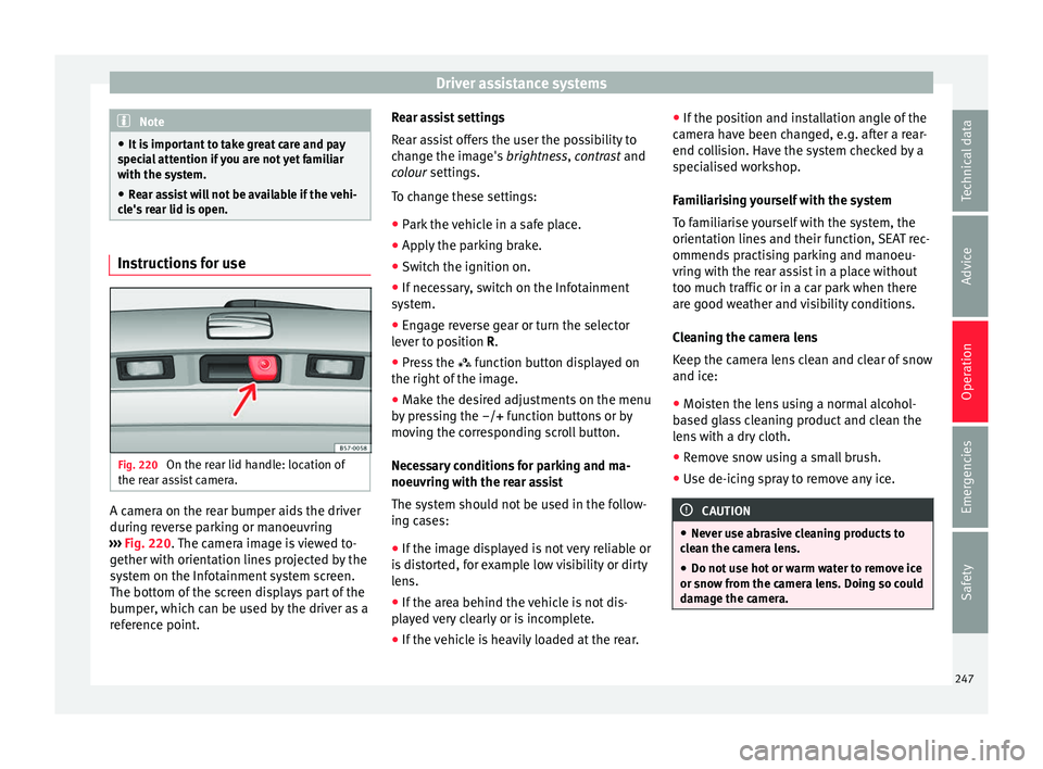
Fig. 220
On the rear lid handle: location of
the r e
ar a
ssist camera. A camera on the rear bumper aids the driver
durin
g r
ev
erse parking or manoeuvring
››› Fig. 220. The camera image is viewed to-
gether with orientation lines projected by the
system on the Infotainment system screen.
The bottom of the screen displays part of the
bumper, which can be used by the driver as a
reference point. Rear assist settings
Rear a
ssist offers the user the possibility to
change the image's brightness, contrast and
colour settings.
To change these settings:
● Park the vehicle in a safe place.
● Apply the parking brake.
● Switch the ignition on.
● If necessary, switch on the Infotainment
syst
em.
● Engage reverse gear or turn the selector
lever t
o position R.
● Press the function b
utton displayed on
the right of the image.
● Make the desired adjustments on the menu
by pr
essing the –/+ function buttons or by
moving the corresponding scroll button.
Necessary conditions for parking and ma-
noeuvring with the rear assist
The system should not be used in the follow-
ing cases:
● If the image displayed is not very reliable or
is di
storted, for example low visibility or dirty
lens.
● If the area behind the vehicle is not dis-
pla
yed very clearly or is incomplete.
● If the vehicle is heavily loaded at the rear. ●
If the pos
ition and installation angle of the
camera have been changed, e.g. after a rear-
end collision. Have the system checked by a
specialised workshop.
Familiarising yourself with the system
To familiarise yourself with the system, the
orientation lines and their function, SEAT rec-
ommends practising parking and manoeu-
vring with the rear assist in a place without
too much traffic or in a car park when there
are good weather and visibility conditions.
Cleaning the camera lens
Keep the camera lens clean and clear of snow
and ice:
● Moisten the lens using a normal alcohol-
based gl
ass cleaning product and clean the
lens with a dry cloth.
● Remove snow using a small brush.
● Use de-icing spray to remove any ice. CAUTION
● Never u se abr
asive cleaning products to
clean the camera lens.
● Do not use hot or warm water to remove ice
or snow fr
om the camera lens. Doing so could
damage the camera. 247
Technical data
Advice
Operation
Emergencies
Safety