run flat Seat Ateca 2017 Owner's Manual
[x] Cancel search | Manufacturer: SEAT, Model Year: 2017, Model line: Ateca, Model: Seat Ateca 2017Pages: 328, PDF Size: 6.36 MB
Page 55 of 328

The essentials
Repairing a tyre with the anti-punc-
t ur
e kit Fig. 67
Standard representation: contents of
the anti-p u
ncture kit. The anti-puncture kit is located under the
floor p
anel
in the luggage compartment.
Sealing the tyre
● Unscrew the tyre valve cap and insert. Use
the ››
› Fig. 67 1 tool to remove the insert.
Pl ac
e it on a clean surface.
● Shake the tyre sealant bottle vigorously
››
› Fig. 67 10 .
● Screw the inflator tube ››
› Fig. 67 3 into
the se al
ant bottle. The bottle's seal will break
automatically. ●
Remo
ve the lid from the filling tube
››› Fig. 67 3 and screw the open end of the
t ube int
o the tyre valve.
● With the tyre sealant bottle upside down,
fil
l the tyre with the contents of the sealant
bottle.
● Remove the bottle from the valve.
● Place the insert back into the tyre valve us-
ing the t
ool ››› Fig. 67 1 .
Infl atin
g the tyre
● Screw the compressor tyre inflator tube
››
› Fig. 67 5 into the tyre valve.
● Check that the air bleed screw is closed
› ›
› Fig. 67 7 .
● Start the engine and leave it running.
● Insert the connector ››
› Fig. 67 9 into the
v ehic
le's 12-volt socket ›››
page 148.
● Turn the air compressor on with the ON/OFF
swit
ch ››› Fig. 67 8 .
● Keep the air compressor running until it
r e
aches 2.0 to 2.5 bar
(29-36 psi/200-250 kPa). a maximum of 8
minutes.
● Disconnect the air compressor.
● If it does not reach the pressure indicated,
un
screw the tyre inflator tube from the valve.
● Move the vehicle 10m so that the sealant is
di s
tributed throughout the tyre. ●
Sc r
ew the compressor tyre inflator into the
valve.
● Repeat the inflation process.
● If the indicated pressure still cannot be
re
ached, the tyre is too badly damaged. Stop
and request assistance from an authorised
technician.
● Disconnect the air compressor. Unscrew
the tyr
e inflator tube from the tyre valve.
● When the tyre pressure is between 2.5 and
2.0 bar
s, continue driving without exceeding
80 km/h (50 mph).
● Check the pressure again after 10 minutes
››
› page 85.
››› in TMS (Tyre Mobility System)* on
page 83
››› page 83 53
Page 61 of 328
The essentials
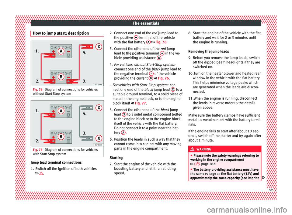
How to jump start: description Fig. 76
Diagram of connections for vehicles
w ithout
Start Stop system Fig. 77
Diagram of connections for vehicles
w ith
Start Stop system Jump lead terminal connections
1. Switch off the ignition of both vehicles
››
› . 2. Connect one end of the
re
d jump lead to
the positive + terminal of the vehicle
w ith the fl
at battery A
› ››
Fig. 76 .
3. Connect the other end of the re
d jump
lead to the positive terminal + in the ve-
hic l
e providing assistance B .
4. For vehicles without Start-Stop system:
connect
one end of the black jump lead to
the negative terminal – of the vehicle
pr o
viding the current B
› ››
Fig. 76 .
– For vehicles with Start-Stop system: con-
nect
one end of the black jump lead X to a
s uit
able ground terminal, to a solid piece of
metal in the engine block, or to the engine
block itself ››› Fig. 77.
5. Connect the other end of the blac
k jump
lead X to a solid metal component bolted
t o the en
gine block or to the engine block
itself of the vehicle with the flat battery.
Do not connect it to a point near the bat-
tery A .
6. Position the leads in such a way that they cannot
come into contact with any moving
parts in the engine compartment.
Starting
7. Start the engine of the vehicle with the boos
ting battery and let it run at idling
speed. 8. Start the engine of the vehicle with the flat
batt
ery and wait for 2 or 3 minutes until
the engine is running.
Removing the jump leads
9. Before you remove the jump leads, switch off the dip
ped beam headlights if they are
switched on.
10.Turn on the heater blower and heated rear windo
w in the vehicle with the flat battery.
This helps minimise voltage peaks which
are generated when the leads are discon-
nected.
11.When the engine is running, disconnect the le
ads in reverse order to the details
given above.
Make sure the battery clamps have sufficient
metal-to-metal contact with the battery termi-
nals.
If the engine fails to start after about 10 sec-
onds, switch off the starter and try again after
about 1 minute. WARNING
● Ple
ase note the safety warnings referring to
working in the engine compartment
››› page 282.
● The battery providing assistance must have
the same
voltage as the flat battery (12V) and
approximately the same capacity (see imprint » 59
Page 124 of 328
Operation
for a long period of time. The alarm system
r
em
ains activated.
● If, after the audible warning goes off, an-
other monitor
ed area is accessed (e.g. the
rear lid is opened after a door has been
opened), the alarm is triggered again.
● The anti-theft alarm is not activated when
the v
ehicle is locked from within using the
central locking button .
● If the driver door is unlocked mechanically
w ith the k
ey, only the driver door is unlocked,
the rest of the doors remain locked. Only
when the ignition has been turned on will the
other doors be available - but not unlocked -
and the central locking button will be activa-
ted.
● If the vehicle battery is run down or flat
then the anti-theft
alarm will not operate cor-
rectly.
● Vehicle monitoring remains active even if
the batt
ery is disconnected or not working for
any reason.
● The alarm is triggered immediately if one of
the batt
ery cables is disconnected while the
alarm system is active. Vehicle interior monitoring and anti-
t
o
w system* It is a monitoring or control function incorpo-
r
at
ed in the anti-theft alarm* which detects
unauthorised vehicle entry by means of ultra-
sound. Activation
– It is automatically switched on when the
anti-theft
alarm is activated.
Deactivation – Open the vehicle with the key, either me-
ch
anically or by pressing the button on
the r emot
e control. The time period from
when the door is opened until the key is in-
serted in the contact should not exceed 15
seconds, otherwise the alarm will be trig-
gered.
– Press the button on the remote control
tw ic
e. The volumetric sensor and tilt sen-
sors will be deactivated. The alarm system
remains activated.
The vehicle interior monitoring and the anti-
tow system are automatically switched on
again next time the vehicle is locked.
The vehicle interior monitoring and anti-tow
sensor (tilt sensor) are automatically switch-
ed on when the anti-theft alarm is switched
on. In order to activate it, all the doors and
the rear lid must be closed.
If you wish to switch off the vehicle interior
monitoring and the anti-tow system, it must
be done each time that the vehicle is locked;
if not, they will be automatically switched on.
The vehicle interior monitoring and the anti-
tow system should be switched off if animals
are left inside the locked vehicle (otherwise, their movements will trigger the alarm) or
when, for e
xample, the vehicle is transported
or has to be towed with only one axle on the
ground.
False alarms
Interior monitoring will only operate correctly
if the vehicle is completely closed. Please ob-
serve related legal requirements.
The following cases may cause a false alarm:
● Open windows (partially or fully).
● Panoramic/tilting sunroof open (partially or
comp
letely).
● Movement of objects inside the vehicle,
suc
h as loose papers, items hanging from
the rear vision mirror (air fresheners), etc. Note
● If the
vehicle is relocked and the alarm is
activated without the volumetric sensor func-
tion, relocking will activate the alarm with all
its functions, except the volumetric sensor.
This function is reactivated when the alarm is
switched on again, unless it is deliberately
switched off.
● If the alarm has been triggered by the volu-
metric sen
sor, this will be indicated by a
flashing of the warning lamp on the driver
door when the vehicle is opened. The flash is
different to the flash indicating the alarm is
activated. 122
Page 151 of 328
Transport and practical equipment
Electrical equipment can be connected to the
12 v
olt power socket. The appliances connec-
ted to each power socket must not exceed a
power rating of 120 Watt. WARNING
The power socket works only when the igni-
tion i s
on. Improper use may cause serious
injury or even fire. Children should therefore
not be left in the vehicle unattended if the
button is also left behind. Otherwise there is
a possibility that they may be injured. CAUTION
Always use the correct type of plugs to avoid
d am
aging the sockets. Note
The use of electrical appliances with the en-
gine sw it
ched off will cause a battery dis-
charge. Storing objects
Lo
ading the luggage compartment All luggage and other loose objects must be
s
af
ely secured in the luggage compartment.
Unsecured objects which shift back and forth
could impair the driving safety or driving characteristics of the vehicle by shifting the
centr
e of gravity.
– Distribute the load evenly in the luggage
comp
artment.
– Place heavy objects as far forward as possi-
bl
e in the luggage compartment.
– Place the heavy objects first.
– Secure heavy objects to the fitted fastening
ring
s ››› page 151. WARNING
● Loo
se luggage and other objects in the lug-
gage compartment could cause serious inju-
ries.
● Always stow objects in the luggage com-
par
tment and secure them on the fastening
rings.
● Use suitable straps to secure heavy ob-
ject
s.
● During sudden manoeuvres or accidents,
loose o
bjects can be thrown forward, injuring
vehicle occupants or passers-by. This in-
creased risk of injury will be further increased
if a loose object is struck by an inflating air-
bag. If this happens, objects may shoot out-
ward like a missile. Risk of fatal injury.
● Please note that the centre of gravity may
shift
when transporting heavy objects; this
may affect vehicle handling and lead to an ac-
cident. Therefore, it is essential to adjust
your speed and driving style accordingly, to
avoid accidents. ●
Nev er e
xceed the allowed axle weights or
allowed maximum weight. If said weights are
exceeded, the driving characteristics of the
vehicle may change, leading to accidents, in-
juries and damage to the vehicle.
● Never leave your vehicle unattended, espe-
ci
ally when the rear lid is open. Children
could climb into the luggage compartment,
closing the door behind them; they will be
trapped and run the risk of death.
● Never allow children to play in or around
the v
ehicle. Close and lock all the doors and
rear lid when you leave the vehicle. Before
you lock the vehicle, make sure that there are
no adults or children in the vehicle. Note
● Air c ir
culation in the vehicle helps reduce
fogging of the windows. Used air escapes
through ventilation slits in the side trim of
the luggage compartment. Ensure that the
ventilation slots are never covered.
● Straps for securing the load to the fasten-
ing rin
gs are commercially available. 149
Technical data
Advice
Operation
Emergencies
Safety
Page 173 of 328
Driving
● To s
top the braking process, release the
button or press the accelerator. WARNING
The improper use of the electronic parking
br ak
e can cause accidents and serious injury.
● Never use the electronic parking brake to
st
op the vehicle, unless it is an emergency.
Braking distances can be considerably lon-
ger, since, under certain circumstances, only
the rear wheels brake. Always use the foot
brake.
● Never accelerate from the engine when a
ge
ar range or a gear is engaged and the en-
gine is running. The vehicle could move, even
if the electronic parking brake is activated. CAUTION
To prevent the vehicle from unintentionally
mo v
ing when parking it, first apply the elec-
tronic parking brake and then remove your
foot from the brake pedal. Note
● In v
ehicles with a manual gearbox, releas-
ing the clutch and accelerating at the same
time automatically disconnects the electronic
parking brake.
● If the vehicle battery is flat, it will not be
pos
sible to disconnect the electronic parking
brake. Use the jump-start ›››
page 58. ●
When the el ectr
onic parking brake is ap-
plied or released, noises may be heard.
● The system performs automatic and audi-
bl
e tests sporadically in the parked vehicle if
some time elapses without the electronic
parking brake being used. Parking
The electronic parking brake should always
be ap
p
lied when the vehicle is parked.
Always note the following points when park-
ing the vehicle: – Use the brake pedal to stop the vehicle.
– Apply the electronic parking brake.
– Put it in 1st gear.
– Switch the engine off and remove the key
from the ignition.
Turn the steering wheel
slightly to engage the steering lock.
– Never leave a vehicle key in the vehicle.
Addition
al notes on parking the vehicle on
gradients:
Turn the steering wheel so that the vehicle
rolls against the kerb if it started to roll.
● If the vehicle is parked facing downhi
ll,
turn the front wheels so that they point to-
wards the kerb . ●
If the
vehicle is parked facing uphill, turn
the front wheels so that they point away from
the kerb.
● Secure the vehicle as usual by applying the
electr
onic parking brake firmly and putting it
in 1st gear. WARNING
● Tak
e measures to reduce the risk of injury
when you leave your vehicle unattended.
● Never park where the hot exhaust system
cou
ld ignite inflammable materials, such as
dry grass, low bushes, spilt fuel etc.
● Never allow vehicle occupants to remain in
the v
ehicle when it is locked. They would be
unable to open the vehicle from the inside,
and could become trapped in the vehicle in
an emergency. In the event of an emergency,
locked doors will delay assistance to vehicle
occupants.
● Never leave children alone in the vehicle.
They c
ould set the vehicle in motion, for ex-
ample, by releasing the electronic parking
brake or the gearshift lever, which would
cause the vehicle to move, but uncontrolla-
bly.
● Depending on weather conditions, it may
become e
xtremely hot or cold inside the vehi-
cle. This can be fatal. 171
Technical data
Advice
Operation
Emergencies
Safety
Page 194 of 328
Operation
● The en gine i
s running.
Switching the Auto Hold function on and off
Press the button ››› . The control lamp on
the b utt
on goes out when the Auto Hold func-
tion is switched off.
Automatically engaging and disengaging the
Auto Hold function
If the Auto Hold function was switched on
with the button before disengaging the ig-
nition, the function will remain on after the
ignition is re-engaged.
If the Auto Hold function was not switched
on, it will automatically remain off next time
the ignition is engaged.
The Auto Hold function is automatically
switched on if the following conditions are
met:
All conditions must be met at the same time
››› :
Manual gearboxAutomatic gearbox
1.The vehicle is kept stationary with the brake ped-
al on a flat surface or on a slope.
2.The engine rotates “correctly”.
All conditions must be met at the same time
››› :
Manual gearboxAutomatic gearbox
Upon pressing the
clutch and accelerating
at the same time, the
brake releases gradu-
ally.Upon accelerating, the
brake releases gradu-
ally. The Auto Hold function is automatically
t
urned off
if the following conditions are
met:
Manual gearboxAutomatic gearbox
1.
If any of the conditions mentioned on
››› page 191, Conditions for keeping the vehicle
stationary with the Auto Hold function are no lon- ger met.
2.If the engine is running irregularly or an anomalyis detected.
3.If the engine is turnedoff or stalls.If the engine is switch- ed off.
4.The clutch and the ac-
celerator are pressed at the same time.If the accelerator is pressed.
5.
If any of the tyres hasonly minimal contact
with the ground, e.g. in the case of axle articu- lation. WARNING
The smart technology incorporated into the
Aut o Ho
ld function cannot defy the laws of
physics; it only works within the limits of the
system. The greater convenience provided by
the Auto Hold function should never tempt
you to take any risk that may compromise
safety.
● Never leave the vehicle running and with
the Auto Ho
ld function switched on.
● The Auto Hold function cannot always keep
the v
ehicle stationary uphill or downhill or
stop it sufficiently, for example, on slippery
or frozen surfaces. Note
Before entering a car wash, always switch off
the Aut o Ho
ld function, because if the elec-
tronic parking brake is automatically connec-
ted, it may cause damage. 192
Page 263 of 328
Towing bracket device*
the anti-theft system, have these checked out
b
y
a specialised workshop.
● If the trailer accessories consume energy
through the po
wer socket to the trailer and
the engine is turned off, the battery will dis-
charge.
● If the vehicle battery is running low, the
electric
al connection with the trailer will be
automatically cut. Loading a trailer
Technically permissible maximum trailer
w
eight
and vertical load on the coupling de-
vice
The technically permissible maximum trailer
weight is the weight that the vehicle can tow
››› . The vertical load on the coupling load
i s
exerted vertically from above on the tow
hitch of the towing bracket ››› page 303.
The information on the maximum trailer
weight and vertical load on the coupling de-
vice contained in the type plate of the towing
bracket are experimental values only. The
correct figures for your specific model, which
may be lower than these figures, are given in
the vehicle documentation. The information
in the vehicle documentation takes prece-
dence at all times.
To promote safety while driving, SEAT recom-
mends making the most of the maximum ver-tical load
technically permissible on the cou-
p
ling device ››› page 255. An insufficient ver-
tical load has a negative influence on the be-
haviour of both the vehicle and trailer.
The vertical load increases the weight on the
rear axle, reducing the vehicle's carrying ca-
pacity.
Gross combination weight of the towing ve-
hicle and trailer
The gross combination weight is the actual
weight of the loaded vehicle plus the actual
weight of the loaded trailer.
In some countries trailers are classified into
distinct categories. SEAT recommends ob-
taining information from a specialised work-
shop regarding which type of trailer is most
suitable for your vehicle.
Trailer loading
The weight of the towing vehicle and trailer
must be balanced. In order to do this, the
load must be as close as possible to the max-
imum vertical load technically permissible on
the coupling point, and it must be evenly dis-
tributed between the back and front of the
trailer:
● Distribute loads in the trailer so that heavy
ob
jects are as near to the axle as possible or
above it.
● Secure the trailer load properly. Tyre pressure
Set the ty
re pressure of the trailer tyres in ac-
cordance with the trailer manufacturer's rec-
ommendations.
When towing a trailer, inflate the tyres of the
towing vehicle with the maximum allowable
pressure ››› page 292. WARNING
If the maximum permissible axle weight, the
m ax
imum load technically permissible on the
coupling point, the maximum authorised ve-
hicle weight or the gross combination weight
of the towing vehicle and trailer are excee-
ded, accidents and serious injuries may oc-
cur.
● Never exceed the values indicated!
● The actual weight on the front and rear
axl
es must never exceed the maximum per-
missible axle weight. The weight on the front
and rear axles must never exceed the maxi-
mum permissible weight. WARNING
A shift in weight could jeopardize the stabili-
ty and sec
urity of the towing vehicle and
trailer, which could lead to accidents and se-
rious injuries.
● Always load the trailer correctly.
● Always secure the load properly using belts
or str
aps that are suitable and in good condi-
tion. 261
Technical data
Advice
Operation
Emergencies
Safety
Page 277 of 328
Intelligent technology
parked. It controls the supply of power to the
v ariou
s electrical devices while the ignition is
switched off. The system takes the battery di-
agnosis data into consideration.
Depending on the power level of the battery,
switch off the individual electrical devices
one after the other to prevent the battery
from losing too much charge and to ensure
that the engine can be started reliably.
Dynamic power management
While the vehicle is moving, this function dis-
tributes the available power to the various
electrical devices and systems according to
their requirements. The power management
ensures that on-board systems do not con-
sume more electrical power than the alterna-
tor can supply, and thus maintains the maxi-
mum possible battery power level. Note
● Neither i s
the power management system
able to overcome the given physical limits.
Please remember that the power and useful
life of the battery are limited.
● When there is a risk that the vehicle will
not s
tart, the alternator power failure or low
battery charge level warning lamp will be
shown ››› page 106. Flat battery
Starting ability has first priority.
Shor
t
trips, city traffic and low temperatures
all place a heavy load on the battery. In these
conditions a large amount of power is con-
sumed, but only a small amount is supplied.
The situation is also critical if electrical devi-
ces are in use when the engine is not run-
ning. In this case power is consumed when
none is being generated.
In these situations you will be aware that the
power management system is intervening to
control the distribution of electrical power.
When the vehicle is parked for long periods
If you do not drive your vehicle for a period of
several days or weeks, the power manage-
ment will gradually shut off the electrical de-
vices one by one or reduce the amount of cur-
rent they are using. This limits the amount of
power consumed and helps to ensure relia-
ble starting even after a long period. Some
convenience functions, such as remote vehi-
cle opening, may not be available under cer-
tain circumstances. These functions will be
restored when you switch on the ignition and
start the engine. With the engine switched off
F
or e
xample, if you listen to the sound sys-
tem with the engine switched off the battery
will run down.
If the energy consumption means there is a
risk that the engine will not start, a text will
appear in vehicles with a driver information
system*.
This driver indicator tells you that you must
start the engine so that the battery can re-
charge.
When the engine is running
Although the alternator generates electrical
power, the battery can still become dis-
charged while the vehicle is being driven.
This can occur when a lot of power is being
consumed but only a small amount supplied,
especially if the battery is not fully charged
initially.
To restore the necessary energy balance, the
system will then temporarily shut off the elec-
trical devices that are using a lot of power, or
reduce the current they are consuming. Heat-
ing systems in particular use a large amount
of electrical power. If you notice, for instance,
that the seat heating* or the rear window
heater is not working, they may have been
temporarily switched off or regulated to a
lower heat output. These systems will be
available again as soon as sufficient electri-
cal power is available. »
275
Technical data
Advice
Operation
Emergencies
Safety
Page 291 of 328
Checking and refilling levels
CAUTION
● Do not mi
x cleaning products recommen-
ded by SEAT with other products. This could
lead to flocculation and may block the wind-
screen washer jets.
● When topping up service fluids, make abso-
lutely
certain that you fill the fluids into the
correct reservoirs. Using the wrong fluids
could cause serious malfunctions and engine
damage!
● Not having windscreen wiper fluid reduces
vi
sibility through the windscreen, and leads
to loss of visibility in headlights in models
with headlight washer. Battery
Gener a
l information Read the additional information carefully
› ›
› page 50.
The battery is located in the engine compart-
ment and is almost maintenance-free. It is
checked as part of the Inspection Service.
Nevertheless, check the terminals are clean
and have the correct tightening torque, espe-
cially in summer and winter.
Disconnecting the battery
The battery should only be disconnected in
exceptional cases. When the battery is dis- connected, some of the vehicle's functions
are “lo
st” (››› table on page 289). These
functions will require resetting after the bat-
tery is reconnected.
Deactivate the anti-theft alarm* before you
disconnect the battery Otherwise the alarm
will be triggered.
FunctionReprogramming
One-touch function of
the electric windows››› page 128, One-touch
opening and closing.
Remote control key
If the vehicle does not re-
spond to the key, they
should be synchronised
››› page 120.
Digital clock››› page 104.
ESC warning lampAfter driving for a few me-
tres, the warning lamp goes
out again. If the vehicle is not used for long periods
The
v
ehicle has a system for monitoring the
current consumption when the engine is left
unused for long periods of time ››› page 274.
Some functions, such as the interior lights, or
the remote door opening, may be temporarily
disabled to prevent the battery from running
flat. These functions will come back on as
soon as the ignition is switched on and the
engine started. Winter conditions
Durin
g the winter, the starting power may be
reduced, and if necessary, the battery should
be charged ››› in Important safety warn-
in g
s for handling a vehicle battery on
page 290
Important safety warnings for han-
dling a
vehicle battery All work on batteries requires specialist
kno
wl
edge. Please refer to a SEAT Official
Service or a workshop specialising in batter-
ies: risk of burns or exploding battery!
The battery must not be opened. Never try to
change the fluid level of the battery. Other-
wise explosive gas is released from the bat-
tery that could cause an explosion.
Wear eye protection.
Battery acid is very corrosive and caustic. Wear
protective gloves and eye protection. In the event
of electrolyte splashes, rinse off with plenty of
water.
Fires, sparks, open flames and smoking are pro-
hibited.
The battery should only be charged in a well-ven-
tilated zone. Risk of explosion!
Keep children away from acid and batteries!»
289
Technical data
Advice
Operation
Emergencies
Safety
Page 294 of 328
Advice
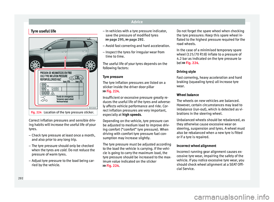
Tyre useful life Fig. 224
Location of the tyre pressure sticker. Correct inflation pressures and sensible driv-
in
g h
abits will increase the useful life of your
tyres.
– Check tyre pressure at least once a month,
and also prior t
o any long trip.
– The tyre pressure should only be checked
when the tyr
es are cold. Do not reduce the
pressure of warm tyres.
– Adjust tyre pressure to the load being car-
ried by
the vehicle. –
In v
ehicles with a tyre pressure indicator,
save the pressure of modified tyres
››› page 295, ››› page 292.
– Avoid fast cornering and hard acceleration.
– Inspect the tyres for irregular wear from
time to time.
The u
seful life of your tyres depends on the
following factors:
Tyre pressure
The tyre inflation pressures are listed on a
sticker inside the driver door pillar
››› Fig. 224.
Insufficient or excessive pressure greatly re-
duces the useful life of the tyres and adverse-
ly affects vehicle performance and ride. Cor-
rect inflation pressures are very important,
especially at high speeds.
Depending on the vehicle, tyre pressure can
be adjusted to medium load to improve driv-
ing comfort (“comfort” tyre pressure). When
driving with comfort tyre pressure fuel con-
sumption may increase slightly.
The tyre pressure must be adjusted according
to the load the vehicle is carrying. If the vehi-
cle is going to carry the maximum load, the
tyre pressure should be increased to the max-
imum value indicated on the sticker
››› Fig. 224. Do not forget the spare wheel when checking
the tyr
e pressures: Keep this spare wheel in-
flated to the highest pressure required for the
road wheels.
In the case of a minimised temporary spare
wheel (125/70 R18) inflate to a pressure of
4.2 bar as indicated on the tyre pressure la-
bel ››› Fig. 224.
Driving style
Fast cornering, heavy acceleration and hard
braking (squealing tyres) all increase tyre
wear.
Wheel balance
The wheels on new vehicles are balanced.
However, certain circumstances may lead to
imbalance (run-out), which is detected as vi-
brations in the steering wheel.
Unbalanced wheels should be rebalanced, as
they otherwise cause excessive wear on
steering, suspension and tyres. A wheel must
also be rebalanced when a new tyre is fitted
or if a tyre is repaired.
Incorrect wheel alignment
Incorrect running gear alignment causes ex-
cessive tyre wear, impairing the safety of the
vehicle. If you notice excessive tyre wear, you
should check wheel alignment at a SEAT Offi-
cial Service.
292