coolant temperature Seat Ateca 2018 Owner's Manual
[x] Cancel search | Manufacturer: SEAT, Model Year: 2018, Model line: Ateca, Model: Seat Ateca 2018Pages: 348, PDF Size: 7.32 MB
Page 37 of 348
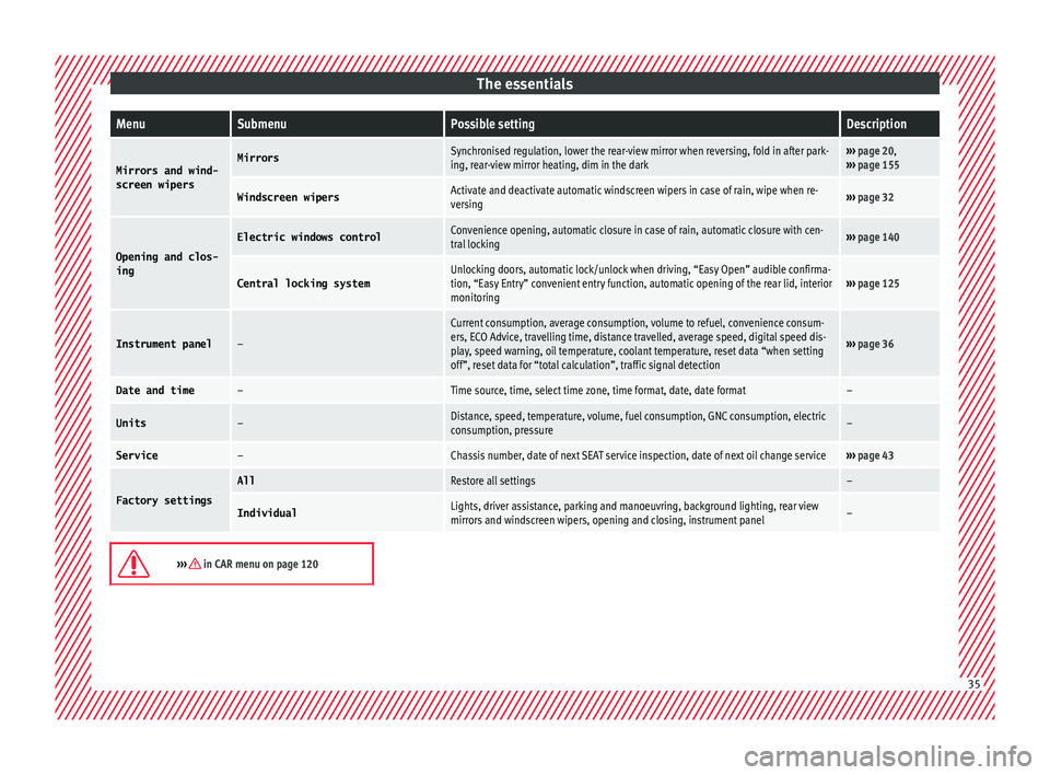
The essentialsMenuSubmenuPossible settingDescription
Mirrors and wind-
screen wipersMirrorsSynchronised regulation, lower the rear-view mirror when reversing, fold in after park-
ing, rear-view mirror heating, dim in the dark››› page 20,
››› page 155
Windscreen wipersActivate and deactivate automatic windscreen wipers in case of rain, wipe when re-
versing››› page 32
Opening and clos-
ing
Electric windows controlConvenience opening, automatic closure in case of rain, automatic closure with cen-
tral locking››› page 140
Central locking systemUnlocking doors, automatic lock/unlock when driving, “Easy Open” audible confirma-
tion, “Easy Entry” convenient entry function, automatic opening of the rear lid, interior
monitoring››› page 125
Instrument panel–
Current consumption, average consumption, volume to refuel, convenience consum-
ers, ECO Advice, travelling time, distance travelled, average speed, digital speed dis-
play, speed warning, oil temperature, coolant temperature, reset data “when setting
off”, reset data for “total calculation”, traffic signal detection
››› page 36
Date and time–Time source, time, select time zone, time format, date, date format–
Units–Distance, speed, temperature, volume, fuel consumption, GNC consumption, electric
consumption, pressure–
Service–Chassis number, date of next SEAT service inspection, date of next oil change service››› page 43
Factory settings
AllRestore all settings–
IndividualLights, driver assistance, parking and manoeuvring, background lighting, rear view
mirrors and windscreen wipers, opening and closing, instrument panel–
››› in CAR menu on page 120
35
Page 41 of 348
The essentials
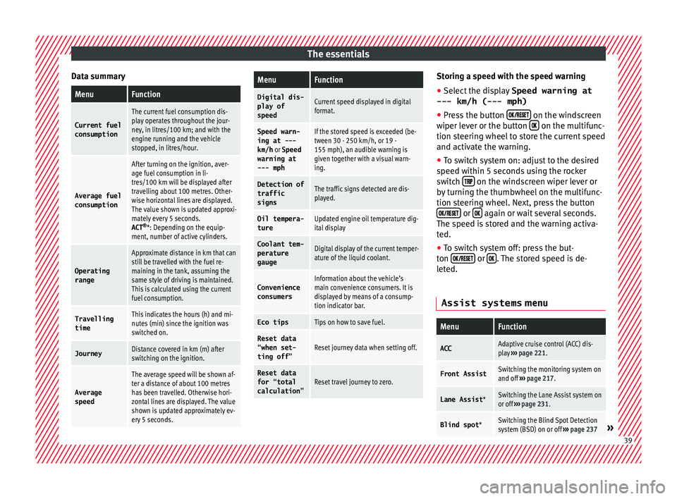
Data summaryMenuFunction
Current fuel
consumption
The current fuel consumption dis-
play operates throughout the jour-
ney, in litres/100 km; and with the
engine running and the vehicle
stopped, in litres/hour.
Average fuel consumption
After turning on the ignition, aver-
age fuel consumption in li-
tres/100 km will be displayed after
travelling about 100 metres. Other-
wise horizontal lines are displayed.
The value shown is updated approxi-
mately every 5 seconds.
ACT ®
*: Depending on the equip-
ment, number of active cylinders.
Operating range
Approximate distance in km that can
still be travelled with the fuel re-
maining in the tank, assuming the
same style of driving is maintained.
This is calculated using the current
fuel consumption.
Travelling timeThis indicates the hours (h) and mi-
nutes (min) since the ignition was
switched on.
JourneyDistance covered in km (m) after
switching on the ignition.
Average
speed
The average speed will be shown af-
ter a distance of about 100 metres
has been travelled. Otherwise hori-
zontal lines are displayed. The value
shown is updated approximately ev-
ery 5 seconds.
MenuFunction
Digital dis-
play of
speedCurrent speed displayed in digital
format.
Speed warn-
ing at ---
km/h or Speed
warning at
--- mphIf the stored speed is exceeded (be-
tween 30 - 250 km/h, or 19 -
155 mph), an audible warning is
given together with a visual warn-
ing.
Detection of
traffic
signsThe traffic signs detected are dis-
played.
Oil tempera- tureUpdated engine oil temperature dig-
ital display
Coolant tem-
perature
gaugeDigital display of the current temper-
ature of the liquid coolant.
Convenience consumersInformation about the vehicle’s
main convenience consumers. It is
displayed by means of a consump-
tion indicator bar.
Eco tipsTips on how to save fuel.
Reset data “when set-
ting off”Reset journey data when setting off.
Reset data
for “total
calculation”Reset travel journey to zero. Storing a speed with the speed warning
● Select the display Speed warning at
--- km/h (---
mph)
● Press the button
on the windscreen
w iper l
ev
er or the button on the multifunc-
tion s t
eerin
g wheel to store the current speed
and activate the warning.
● To switch system on: adjust to the desired
speed within 5 sec
onds using the rocker
switch on the windscreen wiper lever or
b y
t
urning the thumbwheel on the multifunc-
tion steering wheel. Next, press the button or
again or wait several seconds.
The s peed i
s
stored and the warning activa-
ted.
● To switch system off: press the but-
ton or
. The stored speed is de-
l et
ed.
Assist systems menu
MenuFunction
ACCAdaptive cruise control (ACC) dis-
play ››› page 221.
Front AssistSwitching the monitoring system on
and off ››› page 217.
Lane Assist *Switching the Lane Assist system on
or off ››› page 231.
Blind spot *Switching the Blind Spot Detection
system (BSD) on or off ››› page 237» 39
Page 50 of 348
The essentials
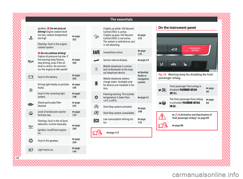
Ignition: Do not carry on
driving! Engine coolant level
too low, coolant temperature
too high
››› page
302
Flashing: Fault in the engine
coolant system.
Do not continue driving!
Engine oil pressure too low. If
the warning lamp flashes,
stop driving, even if the oil
level is correct. Do not even
run the engine at idle speed!
››› page
300
Fault in the battery.›››
page
305
Driving light totally or partially
faulty.›››
page
106
Fault in the cornering light
system.››› page
148
Diesel particulate filter
blocked›››
page
205
Level of windscreen washer
fluid too low.›››
page
153
Flashing: Fault in the oil level
detection. Control manually.
›››
page
300
Ignition: Insufficient engine
oil.
Fault in the gearbox.›››
page
200
Light Assist on.›››
page
146
it lights up white:
Hill Descent
Control (HDC) is active.
it lights up grey: Hill Descent
Control (HDC) is not active.
The system is switched on, but
is not adjusting.
››› page
210
Immobiliser active.›››
page
133
Service interval display›››
page 43
Mobile telephone is connec-
ted via Bluetooth to the origi-
nal telephone device.
›››
Booklet
Audio or
navigation
system
Mobile telephone battery
charge meter. Available only
for devices pre-installed in fac-
tory.
Freezing warning. The outside
temperature is lower than
+4°C (+39°F).›››
page 41
Start-Stop system activated.›››
page
208
Start-Stop system unavailable.
Low consumption driving sta-
tus›››
page
116
›››
page 115 On the instrument panel
Fig. 53
Warning lamp for disabling the front
p a
s
senger airbag.
Front passenger front airbag is
disabled (
).
››› page
89
The front passenger front airbag
is activated (
).
››› page
89
››› in Activation and deactivation of
front passenger airbag* on page 89
››› page 88 48
Page 61 of 348
The essentials
increased, but only up to 60 %; otherwise an-
tifr eez
e pr
otection will diminish and this will
worsen cooling.
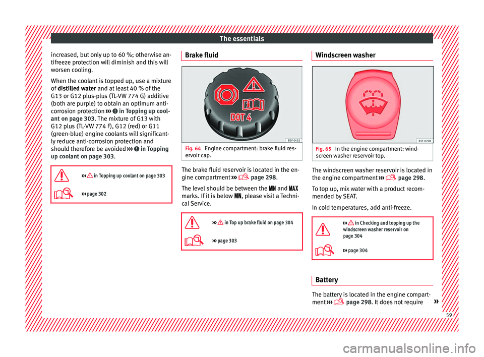
When the coolant is topped up, use a mixture
of distilled water and at least 40 % of the
G13 or G12 plus-plus (TL-VW 774 G) additive
(both are purple) to obtain an optimum anti-
corrosion protection ››› in Topping up cool-
ant on p ag
e 303
. The mixture of G13 with
G12 plus (TL-VW 774 F), G12 (red) or G11
(green-blue) engine coolants will significant-
ly reduce anti-corrosion protection and
should therefore be avoided ››› in Topping
up c oo
l
ant on page 303.
››› in Topping up coolant on page 303
››› page 302 Brake fluid
Fig. 64
Engine compartment: brake fluid res-
er v
oir c
ap. The brake fluid reservoir is located in the en-
gine c
omp
ar
tment ›››
page 298
.
The level should be between the and
marks. If it is below , please visit a Techni-
cal Service.
››› in Top up brake fluid on page 304
››› page 303 Windscreen washer
Fig. 65
In the engine compartment: wind-
s c
r
een washer reservoir top. The windscreen washer reservoir is located in
the en
gine c
omp
artment ›››
page 298.
To top up, mix water with a product recom-
mended by SEAT.
In cold temperatures, add anti-freeze.
››› in Checking and topping up the
windscreen washer reservoir on
page 304
››› page 304 Battery
The battery is located in the engine compart-
ment
›
›
› page 298. It does not require » 59
Page 119 of 348
Instruments and warning/control lamps
Identifying letters on engine (MKB)
Ho l
d the b
utton ››› Fig. 119 4 down for more
th an 15 sec
ond
s to display the identifying
letters of the vehicle engine (MKB). To do
this, the ignition must be switched on and
the engine switched off. WARNING
Observe the safety warnings ›››
in Warning
and contr o
l lamps on page 119. WARNING
Even though outside temperatures are above
freez in
g, some roads and bridges may be icy.
● At outside temperatures above +4°C
(+39°F), even when the “ice c
rystal” symbol
is not visible, there may still be patches of ice
on the road.
● The outside temperature sensor takes a
guideline meas
urement. Note
● Differ ent
versions of the instrument panel
are available and therefore the versions and
instructions on the display may vary. In the
case of displays without warning or informa-
tion texts, faults are indicated exclusively by
the warning lamps.
● Depending on the equipment, some set-
tings
and instructions can also be carried out
in the Easy Connect system. ●
When sever a
l warnings are active at the
same time, the symbols are shown succes-
sively for a few seconds and will stay on until
the fault is rectified. Odometer
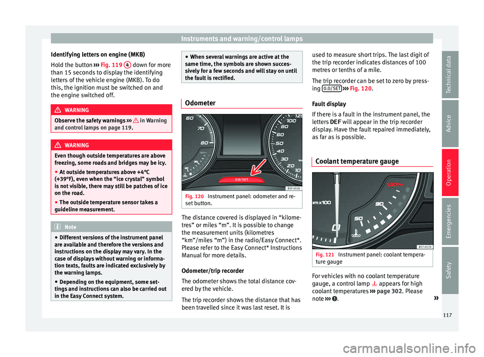
Fig. 120
Instrument panel: odometer and re-
set b
utt
on. The distance covered is displayed in “kilome-
tr
e
s” or mi
les “m”. It is possible to change
the measurement units (kilometres
“km”/miles “m”) in the radio/Easy Connect*.
Please refer to the Easy Connect* Instructions
Manual for more details.
Odometer/trip recorder
The odometer shows the total distance cov-
ered by the vehicle.
The trip recorder shows the distance that has
been travelled since it was last reset. It is used to measure short trips. The last digit of
the trip recor
der indicates distances of 100
metres or tenths of a mile.
The trip recorder can be set to zero by press-
ing 0.0/SET
› ››
Fig. 120
.
F
ault display
If there is a fault in the instrument panel, the
letters DEF will appear in the trip recorder
display. Have the fault repaired immediately,
as far as is possible.
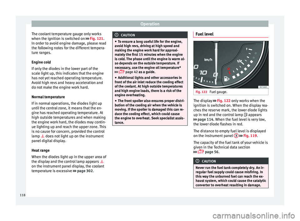
Coolant temperature gauge Fig. 121
Instrument panel: coolant tempera-
t ur
e g
auge For vehicles with no coolant temperature
g
aug
e, a c
ontrol lamp appears for high
coolant temperatures ››› page 302. Please
note ››› .
»
117
Technical data
Advice
Operation
Emergencies
Safety
Page 120 of 348
Operation
The coolant temperature gauge only works
when the ignition i s
sw
itched on ››› Fig. 121.
In order to avoid engine damage, please read
the following notes for the different tempera-
ture ranges.
Engine cold
If only the diodes in the lower part of the
scale light up, this indicates that the engine
has not yet reached operating temperature.
Avoid high revs and heavy acceleration and
do not make the engine work hard.
Normal temperature
If in normal operations, the diodes light up
until the central zone, it means that the en-
gine has reached operating temperature. At
high outside temperatures and when making
the engine work hard, the diodes may contin-
ue lighting up and reach the upper zone. This
is no cause for concern, provided the control
lamp does not light up on the instrument
panel digital display.
Heat range
When the diodes light up in the upper area of
the display and the control lamp appears
on the instrument panel display, the coolant
temperature is excessive ››› page 302. CAUTION
● To en s
ure a long useful life for the engine,
avoid high revs, driving at high speed and
making the engine work hard for approxi-
mately the first 15 minutes when the engine
is cold. The phase until the engine is warm al-
so depends on the outside temperature. If
necessary, use the engine oil temperature*
››› page 42 as a guide.
● Additional lights and other accessories in
front of
the air inlet reduce the cooling effect
of the coolant. At high outside temperatures
and high engine loads, there is a risk of the
engine overheating.
● The front spoiler also ensures proper distri-
bution of the c
ooling air when the vehicle is
moving. If the spoiler is damaged this can re-
duce the cooling effect, which could cause
the engine to overheat. Seek specialist assis-
tance. Fuel level
Fig. 122
Fuel gauge. The display
››
› Fig. 122 only works when the
ignition is switched on. When the display rea-
ches the reserve mark, the lower diode lights
up in red and the control lamp appears
››› page 114. When the fuel level is very low,
the lower diode flashes in red.
The distance to empty fuel level is displayed
on the instrument panel 3
› ›
› Fig. 119
.
The capacity of the fuel tank of your vehicle is
given in the Technical data section
››› page 56. CAUTION
Never run the fuel tank completely dry. An ir-
re gu
lar fuel supply could cause misfiring. In
this way the unburned fuel can reach the ex-
haust system, which could cause the catalytic
converter to overheat resulting in damage. 118
Page 175 of 348
Air conditioningFunction button: Function
It enables activation and deactivation of
the PureAir and opens the submenu.
Air conditioning user instructions
The interior cooling system only works when
the engine i
s
running and fan is switched on.
The air conditioner operates most effectively
with the windows and the panoramic sliding
sunroof closed. However, if the vehicle has
heated up after standing in the sun for some
time, the air inside can be cooled more quick-
ly by opening the windows and the panoram-
ic sliding sunroof briefly.
Climatronic: change the temperature unit on
the screen of the radio or on the factory-fit-
ted navigation system
Changing the temperature display from Cel-
sius to Fahrenheit on radio or on the factory- fitted navigation system is done using the
menu on the ins
trument
panel
››› page 36.
The cooling system cannot be activated
If the air conditioning system cannot be
switched on, this may be caused by the fol-
lowing:
● The engine is not running.
● The fan is switched off.
● The air conditioner fuse has blown.
● The outside temperature is lower than ap-
prox
imately +3°C (+38°F).
● The air conditioner compressor has been
temporari
ly switched off because the engine
coolant temperature is too high.
● Another fault in the vehicle. Have the air
conditioner chec
ked by a specialised work-
shop. Special Characteristics
If the humidity and t
emperature outside the
vehicle are high, condensation can drip off
the evaporator in the cooling system and
form a pool underneath the vehicle. This is
normal and does not indicate a leak! Note
After starting the engine, any residual humid-
ity in the air c onditioner c
ould mist over the
windscreen. Switch on the defrost function as
soon as possible to clear the windscreen of
condensation. 173
Technical data
Advice
Operation
Emergencies
Safety
Page 183 of 348
Driving
Driving St ar
tin
g and stopping the en-
gine
Switching the ignition on and starting
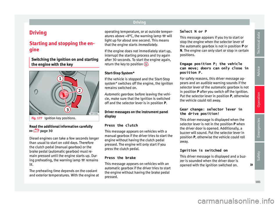
the engine with the key Fig. 177
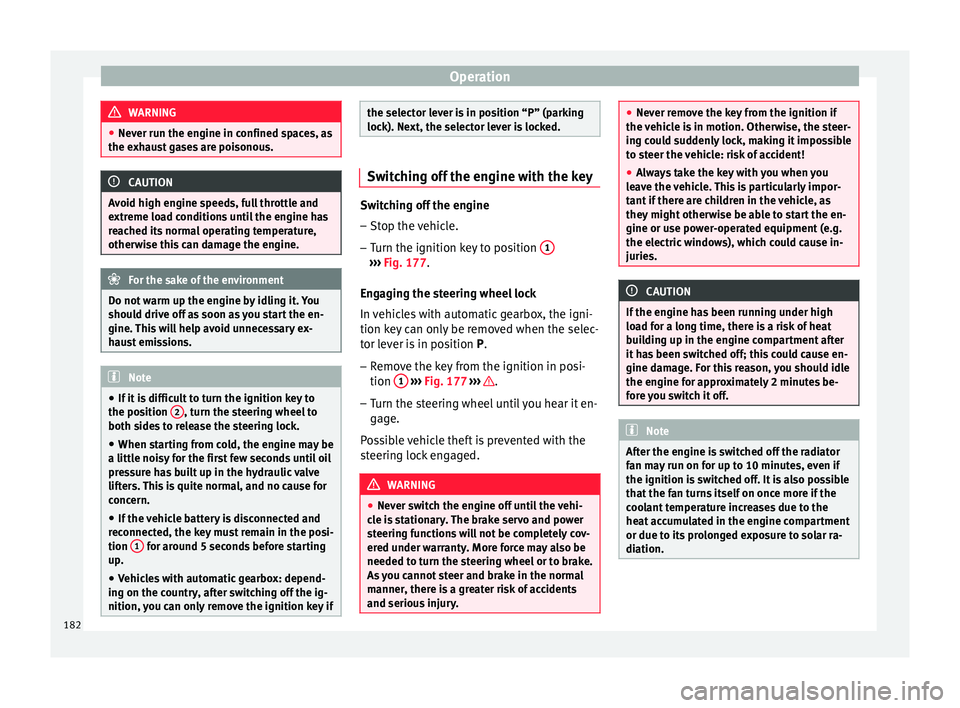
Ignition key positions. Read the additional information carefully
› ›
›
page 30
Diesel engines can take a few seconds longer
than usual to start on cold days. Therefore
the clutch pedal (manual gearbox) or the
brake pedal (automatic gearbox) must re-
main pressed until the engine starts up. Dur-
ing preheating, the warning lamp remains
lit.
The preheating time depends on the coolant
and exterior temperatures. With the engine at operating temperature, or at outside temper-
ature
s above +8°C, the warning lamp will
light up for about one second. This means
that the engine starts immediately.
If the engine does not immediately start up,
interrupt the starting process and try again
after 30 seconds. To start the engine again,
return the key to position 1 .
St ar
t
-Stop System*
If the vehicle is stopped and the Start-Stop
system* switches off the engine, the ignition
remains switched on.
Automatic gearbox: before leaving the vehi-
cle, make sure that the ignition is switched
off and the selector lever is in position P.
Driver messages on the instrument panel
display
Press the clutch
This message appears on vehicles with a
manual gearbox if the driver tries to start the
engine without having the clutch pedal
pressed. The engine will only start if you
press the clutch pedal.
Press the brake This message appears on vehicles with an
automatic gearbox if the driver tries to start
the engine without having the brake pedal
pressed. Select N or P
This me
ssage appears if you try to start or
stop the engine when the selector lever of
the automatic gearbox is not in position P or
N. The engine can only start or stop in certain
positions.
Engage position P; the vehicle
can move; doors can only close in
position P.For safety reasons, this driver message ap-
pears and an audible warning sounds if the
selector lever of the automatic gearbox is not
in position P after you switch off the ignition.
Put the selector lever in position P, otherwise
the vehicle could roll away.
Gear change: selector lever in
the drive position! This driver message is displayed when the
selector lever is not in the position P when
the driver door is opened. Additionally, a
buzzer will sound. Put the selector lever in
position P, otherwise the vehicle could roll
away.
Ignition is switched on
This driver message is displayed and a buz-
zer is sounded when the driver door is
opened with the ignition switched on. »
181
Technical data
Advice
Operation
Emergencies
Safety
Page 184 of 348
Operation
WARNING
● Never ru n the en
gine in confined spaces, as
the exhaust gases are poisonous. CAUTION
Avoid high engine speeds, full throttle and
extr eme lo
ad conditions until the engine has
reached its normal operating temperature,
otherwise this can damage the engine. For the sake of the environment
Do not warm up the engine by idling it. You
shoul d driv
e off as soon as you start the en-
gine. This will help avoid unnecessary ex-
haust emissions. Note
● If it i
s difficult to turn the ignition key to
the position 2 , turn the steering wheel to
both side s
to release the steering lock.
● When starting from cold, the engine may be
a little noisy
for the first few seconds until oil
pressure has built up in the hydraulic valve
lifters. This is quite normal, and no cause for
concern.
● If the vehicle battery is disconnected and
reconnect
ed, the key must remain in the posi-
tion 1 for around 5 seconds before starting
up.
● Vehic
les with automatic gearbox: depend-
ing on the cou
ntry, after switching off the ig-
nition, you can only remove the ignition key if the selector lever is in position “P” (parking
lock). Ne
xt, the sel
ector lever is locked. Switching off the engine with the key
Switching off the engine
– Stop the vehicle.
– Turn the ignition key to position 1 ›››
Fig. 177.
Eng agin
g the steering wheel lock
In vehicles with automatic gearbox, the igni-
tion key can only be removed when the selec-
tor lever is in position P.
– Remove the key from the ignition in posi-
tion 1
› ›
› Fig. 177
››› .
– Turn the steering wheel until you hear it en-
gag
e.
P
ossible vehicle theft is prevented with the
steering lock engaged. WARNING
● Never sw it
ch the engine off until the vehi-
cle is stationary. The brake servo and power
steering functions will not be completely cov-
ered under warranty. More force may also be
needed to turn the steering wheel or to brake.
As you cannot steer and brake in the normal
manner, there is a greater risk of accidents
and serious injury. ●
Never r emo
ve the key from the ignition if
the vehicle is in motion. Otherwise, the steer-
ing could suddenly lock, making it impossible
to steer the vehicle: risk of accident!
● Always take the key with you when you
leav
e the vehicle. This is particularly impor-
tant if there are children in the vehicle, as
they might otherwise be able to start the en-
gine or use power-operated equipment (e.g.
the electric windows), which could cause in-
juries. CAUTION
If the engine has been running under high
loa d f
or a long time, there is a risk of heat
building up in the engine compartment after
it has been switched off; this could cause en-
gine damage. For this reason, you should idle
the engine for approximately 2 minutes be-
fore you switch it off. Note
After the engine is switched off the radiator
fan m a
y run on for up to 10 minutes, even if
the ignition is switched off. It is also possible
that the fan turns itself on once more if the
coolant temperature increases due to the
heat accumulated in the engine compartment
or due to its prolonged exposure to solar ra-
diation. 182
Page 305 of 348
Checking and refilling levels
Topping up coolant
– Wait for the engine to cool down.
– Cover the coolant expansion tank cap with
a c loth and c
ar
efully unscrew it to the left
››› .
– Top up the coolant only if there is still cool-
ant in the e
xp
ansion tank, otherwise you
could damage the engine. If there is no
coolant in the expansion tank, do not con-
tinue driving. You should obtain professio- nal assistance ››› .
– If there is still some coolant in the expan-
sion t
ank, t
op up to the upper mark.
– Top up with coolant until the level becomes
stab
le.
– Screw the cap back on correctly.
Any lo
ss of coolant fluid normally indicates a
leak in the cooling system. Take the vehicle
straight to a specialised workshop to have
the cooling system examined. If there are no
leaks in the engine cooling system, a loss of
coolant can only occur if the coolant boils
and is forced out of the system as a result of
overheating. WARNING
● The coo lin
g system is under pressure. Do
not unscrew the cap on the coolant expan-
sion tank when the engine is hot: risk of
burns! ●
The antifreez e and c
oolant fluid can be a
health hazard. Therefore, the antifreeze
should be stored in the original container in a
safe place out of reach of children. Failure to
comply could result in poisoning.
● If working inside the engine compartment,
remember that, ev
en when the ignition is
switched off, the radiator fan may start up au-
tomatically, and therefore there is a risk of in-
jury. WARNING
If there is not enough anti-freeze in the cool-
ant sys
tem, the engine may fail leading to se-
rious damage.
● Please make sure that the percentage of
additiv
e is correct with respect to the lowest
expected ambient temperature in the zone in
which the vehicle is to be used.
● When the outside temperature is very low,
the cool
ant could freeze and the vehicle
would be immobilised. In this case, the heat-
ing would not work either and inadequately
dressed passengers could die of cold. CAUTION
Do not top up the expansion tank with cool-
ant fluid if it
is empty! Air could enter the
cooling system. In this case, stop driving.
Seek specialist assistance. Otherwise, there
is a risk of engine damage. CAUTION
The original additives should never be mixed
with c oo
lants which are not approved by
SEAT. Otherwise, you run the risk of causing
severe damage to the engine and the engine
cooling system.
● If the fluid in the expansion tank is not pur-
ple b
ut is, for example, brown, this indicates
that the G13 additive has been mixed with an
inadequate coolant. The coolant must be
changed as soon as possible if this is the
case! This could result in serious faults and
engine damage. For the sake of the environment
Coolants and additives can contaminate the
env ir
onment. If any fluids are spilled, they
should be collected and correctly disposed
of, with respect to the environment. Brake fluid
Top up br
ak
e fluid Read the additional information carefully
› ›
›
page 59
Checking the brake fluid level
The brake fluid level must be between the
MIN and MAX markings. »
303
Technical data
Advice
Operation
Emergencies
Safety