lock Seat Exeo 2008 Manual PDF
[x] Cancel search | Manufacturer: SEAT, Model Year: 2008, Model line: Exeo, Model: Seat Exeo 2008Pages: 303, PDF Size: 10.02 MB
Page 227 of 303

Checking and refilling levels225
Safety First
Operating instructions
Practical tips
Te c h n i c a l D a t a
•
A highly explosive mixture of gases is released when the battery is
under charge. The batteries should be charged in a well-ventilated room
only.
•
Keep children away from acid and batteries.
•
Before working on the electrical system, you must switch off the
engine, the ignition and all consumers. The negative cable on the battery
must be disconnected. When a light bulb is changed, you need only switch
off the light.
•
Deactivate the anti-theft alarm by unlocking the vehicle before you
disconnect the battery! The alar m will otherwise be triggered.
•
When disconnecting the battery from the vehicle electrical system,
disconnect first the negative cable and then the positive cable.
•
Switch off all electrical consumers before reconnecting the battery.
Reconnect first the positive cable and then the negative cable. Never
reverse the polarity of the connections. This could cause an electrical fire.
•
Never charge a frozen battery, or one which has thawed. This could
result in explosions and chemical burns. Always replace a battery which
has frozen. A flat battery can freeze at temperatures around 0°
•
Ensure that the vent hose is always connected to the battery.
•
Never use a defective battery. This may be fatally explosive. Replace a
damaged battery immediately.Caution
•
Never disconnect the battery if the ignition is switched on or if the engine
is running. This could damage the electrical system or electronic compo-
nents.
•
Do not expose the battery to direct sunlight over a long period of time, as
the intense ultraviolet radiation can damage the battery housing.
•
If the vehicle is left standing in cold conditions for a long period, protect
the battery from frost. If it “freezes” it will be damaged.
Charging the battery
A fully-charged battery is important for reliable starting.– Note the warnings ⇒ in “Important safety warnings for
handling a car battery” on page 224 and ⇒.
– Switch off the ignition and all electrical equipment.
– Only if “fast-charging”: both battery cables must be discon- nected (first the “negative” cabl e, then the “positive” cable).
– Connect the charger cables to the battery terminals, noting the colour code (red is used for “positive”, black or brown for “nega-
tive”).
– Now connect the battery charger to the power point and switch on.
– After charging the battery: switch off the battery charger and disconnect the power point cable.
– Finally disconnect the charger cables from the battery.
– If necessary, reconnect both battery cables to the battery (first the “positive” cable, then the “negative” cable).When charging with a low current (for instance with a small battery charger)
the battery does not normally have to be disconnected. However, both
battery cables must be disconnected before “ fast-charging” the battery with
a high current. However, always follow th e instructions given by the manufac-
turer of the battery charger.
Fast-charging a battery is dangerous ⇒ in “Important safety warnings for
handling a car battery” on page 224, since it requires a special charger and
WARNING (continued)
Exeo_EN.book Seite 225 Freitag, 17. Oktober 2008 11:24 11
Page 239 of 303
If and when237
Safety First
Operating instructions
Practical tips
Te c h n i c a l D a t a
Tyre mobili ty system
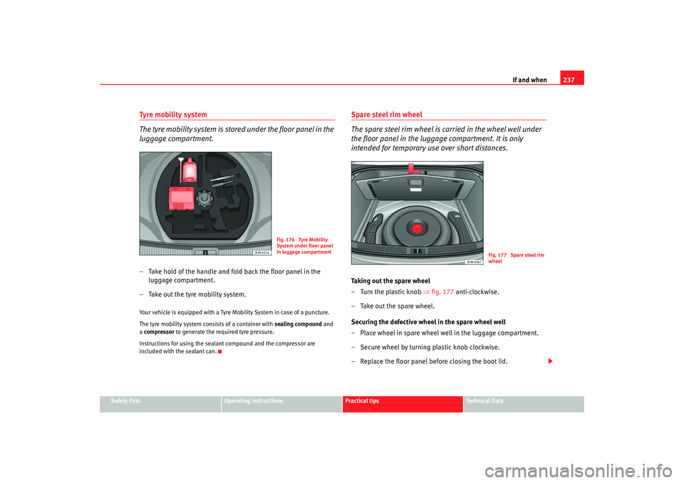
The tyre mobility system is stored under the floor panel in the
luggage compartment.– Take hold of the handle and fold back the floor panel in the
luggage compartment.
– Take out the tyre mobility system.Your vehicle is equipped with a Tyre Mobility System in case of a puncture.
The tyre mobility system consists of a container with sealing compound and
a compressor to generate the required tyre pressure.
Instructions for using the sealant compound and the compressor are
included with the sealant can.
Spare steel rim wheel
The spare steel rim wheel is carried in the wheel well under
the floor panel in the luggage compartment. It is only
intended for temporary use over short distances.Taking out the spare wheel
– Turn the plastic knob ⇒fig. 177 anti-clockwise.
– Take out the spare wheel.
Securing the defective wheel in the spare wheel well
– Place wheel in spare wheel well in the luggage compartment.
– Secure wheel by turning plastic knob clockwise.
– Replace the floor panel before closing the boot lid.
Fig. 176 Tyre Mobility
System under floor panel
in luggage compartment
Fig. 177 Spare steel rim
wheel
Exeo_EN.book Seite 237 Freitag, 17. Oktober 2008 11:24 11
Page 240 of 303

If and when
238Your vehicle can be equipped with a steel spare wheel at the factory. The
spare wheel does not usually meet the same performance standards as the
wheels fitted on the vehicle because of the wheel/tyre dimensions, rubber
composition, tread pattern, etc. Theref ore, note the following restrictions:•
The spare steel rim wheel is designed on ly for your vehicle model. Do not
attempt to mount the wheel on any vehicle but your own.
•
Your vehicle will have different driving characteristics when the spare
steel rim wheel is mounted ⇒.
•
The spare wheel is only intended for temporary use after having a flat tyre.
Replace the spare wheel with a normal wheel that has the proper tyre dimen-
sions as soon as possible.
•
If the size of the spare steel rim wheel is different to that of the other
wheels, it is unlikely that snow chains suitable for the other wheels will fit it.
WARNING
•
After mounting the spare steel rim wheel, the tyre pressure must be
checked and corrected as soon as possible. The inflating pressure must
adapt to the vehicle load (consult th e table containing the inflation pres-
sures). Otherwise there is danger of causing an accident. Use the highest
tyre pressure as indicated in the table.
•
Do not drive faster than 80 km/h, as higher speeds can cause an acci-
dent.
•
Avoid heavy acceleration, hard braking and fast cornering, as this could
cause an accident.
Changing a wheelPreparation work
What you must do before changing a wheel.– If you have a flat tyre or puncture, park the car as far away from the flow of traffic as possible. Choose a location that is as level
as possible.
– All passengers should leave the vehicle. They should wait in a
safe place (e.g. behind the roadside crash barrier).
–Apply the handbrake firmly.
– Engage 1st gear.
– When towing a trailer: Unhitch the trailer from your vehicle.
–Take the tools and the spare wheel ⇒ page 236 out of the
luggage compartment.
WARNING
If you have a puncture in heavy traffic, switch on the hazard warning lights
and place the warning triangle in a visible location. This is for your own
safety and also warns other road users.
Caution
If you have to change the tyre on a gradient, block the wheel opposite the
wheel being changed by placing a stone or similar object under it to prevent
the vehicle from rolling away.
Exeo_EN.book Seite 238 Freitag, 17. Oktober 2008 11:24 11
Page 242 of 303
If and when
240Loosening and tightening the wheel bolts
The wheel bolts must be loosened before raising the vehicle.Loosening
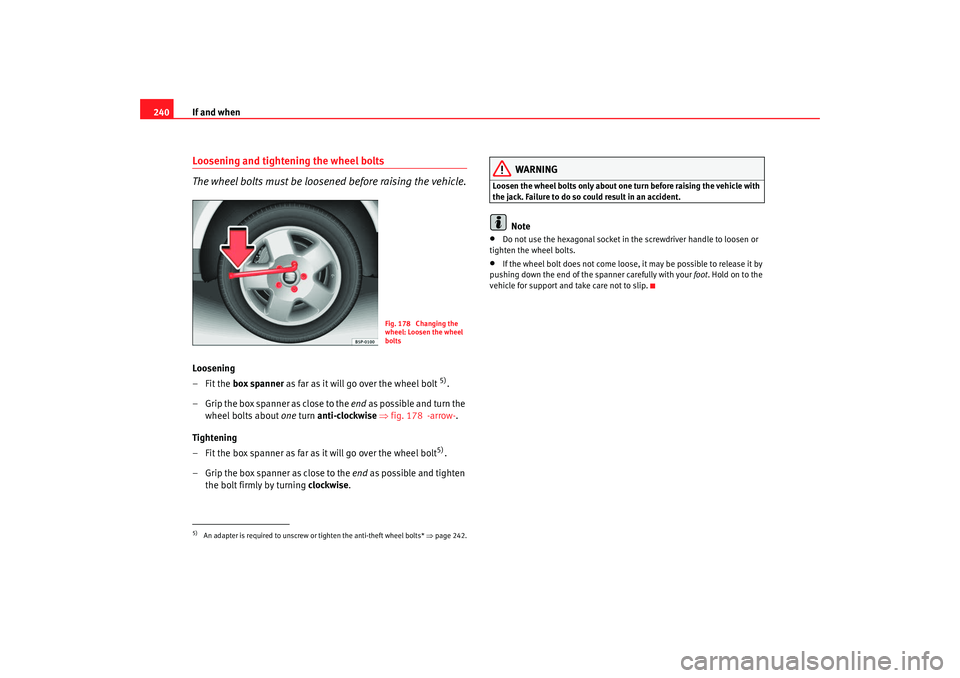
–Fit the box spanner as far as it will go over the wheel bolt
5).
– Grip the box spanner as close to the end as p ossible a nd tu rn the
wheel bolts about one turn anti-clockwise ⇒ fig. 178 -arrow- .
Tightening
– Fit the box spanner as far as it will go over the wheel bolt5).
– Grip the box spanner as close to the end as possible and tighten
the bolt firmly by turning clockwise.
WARNING
Loosen the wheel bolts only about one tu rn before raising the vehicle with
the jack. Failure to do so could result in an accident.
Note
•
Do not use the hexagonal socket in the screwdriver handle to loosen or
tighten the wheel bolts.
•
If the wheel bolt does not come loose, it may be possible to release it by
pushing down the end of the spanner carefully with your foot. Hold on to the
vehicle for support and take care not to slip.
5)An adapter is required to unscrew or tighten the anti-theft wheel bolts* ⇒page 242.
Fig. 178 Changing the
wheel: Loosen the wheel
bolts
Exeo_EN.book Seite 240 Freitag, 17. Oktober 2008 11:24 11
Page 250 of 303
If and when
248Fuse assignment
This list shows the fuses which can be replaced relatively
easily by the owner.No.
Consumer
Amps
1
Climate control
10
2
Footwell lamps
5
3
Heated washer jets
5
4
Radiator fan
5
5
Telephone, multifunction switch, rear window sun
blind
10
6
Air conditioner (air purity sensor), pressure sensor
5
7
Electronic Stabilisation Pro gram (ESP), brake light
switch, clutch pedal switch, steering angle sensor
10
8
Telephone
5
9
Brake servo (vacuum pump)
15
10
Self-directing headlights (adaptive light) right
5
11
Tyre pressure monitoring
12
Diagnostic socket
10
13
Steering column unit
10
14
Brake lights
10
15
instrument panel
10
16
Vacant
5
17
Parking aid, self-levelling suspension, tyre pressure
monitoring system, rain/ light sensor
10
18
Self-directing headlights (adaptive light) left
5
19
Fog lights
15
20
Vacant
21
Vacant
22
Driver's door / front passenger's door
15
23
Rear doors
15
24
Central electrics unit for convenience equipment
20
25
Heater blower
30
26
Rear window heater
30
27
Electrical socket for trailer (control unit)
30
28
Fuel pump, auxiliary pump for diesel
20
29
Vacant
30
Sliding/tilting sunroof
20
31
Diagnosis connection, automatic anti-dazzle interior
mirror with automatic adjustment
15
32
Towing socket
15
33
Lighter
20
34
Vacant
35
Luggage compartment power point*
20
36
Wiper system
30
37
Pump for windscreen washer and headlight washer
system
30
38
Central electrics unit for convenience equipment, bon-
net unlocking
15
39
Radio
20
No.
Consumer
Amps
Exeo_EN.book Seite 248 Freitag, 17. Oktober 2008 11:24 11
Page 254 of 303
If and when
252Changing the turn signal bulb
The procedure for changing the bulbs on the front
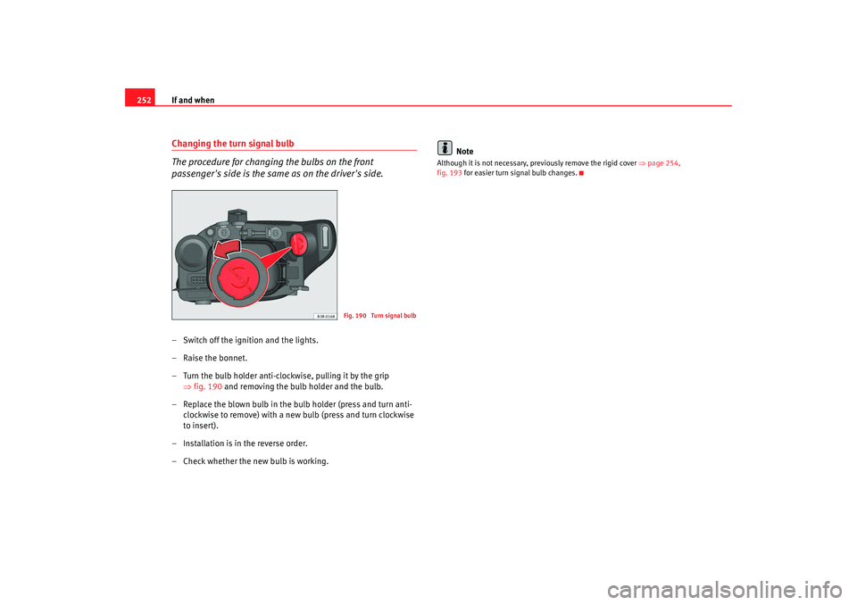
passenger's side is the same as on the driver's side.– Switch off the ignition and the lights.
– Raise the bonnet.
– Turn the bulb holder anti-clockwise, pulling it by the grip
⇒fig. 190 and removing the bulb holder and the bulb.
– Replace the blown bulb in the bulb holder (press and turn anti- clockwise to remove) with a new bulb (press and turn clockwise
to insert).
– Installation is in the reverse order.
– Check whether the new bulb is working. Note
Although it is not necessary, previously remove the rigid cover
⇒page 254,
fig. 193 for easier turn signal bulb changes.
Fig. 190 Turn signal bulb
Exeo_EN.book Seite 252 Freitag, 17. Oktober 2008 11:24 11
Page 256 of 303

If and when
254Changing the dipped beam headlight bulb
The procedure for changing the bulbs on the front
passenger's side is the same as on the driver's side.
– Switch off the ignition and the lights.
–Raise the bonnet.
– Move the brace ⇒fig. 193 in the direction of the arrow and
remove the rigid cover, separating the brace side and then
removing the two tabs from the other end of the cover.
– Pull the connector ⇒fig. 194 from the bulb.
– Unclip the retainer spring ⇒fig. 194 pressing inwards to the
right.
– Remove the bulb and fit the new one in the headlight casing with the tab upwards, starting to position it from below.
– Clip on the spring, raising it and pressing it slightly while turning it anti-clockwise. To ensure correct lighting, the filament must be
vertical. When changing the bulb, you can check the position of
the bulb through the headlight glass.
– Connect the connector to the bulb.
– Fit the cover, first inserting the side tabs and then closing the cover and the brace. Make sure that the gasket sits well on the
casing cover during the operation.
– Check whether the new bulb is working.
– Have the headlight settings checked as soon as possible.
Fig. 193 Dipped head-
lightsFig. 194 Dipped head-
lights
A1A2
A3
Exeo_EN.book Seite 254 Freitag, 17. Oktober 2008 11:24 11
Page 257 of 303
If and when255
Safety First
Operating instructions
Practical tips
Te c h n i c a l D a t a
Changing side light bulb (outside of vehicle)
The procedure for changing the bulbs on the front
passenger's side is the same as on the driver's side.
– Switch off the ignition and the lights.
– Raise the bonnet.
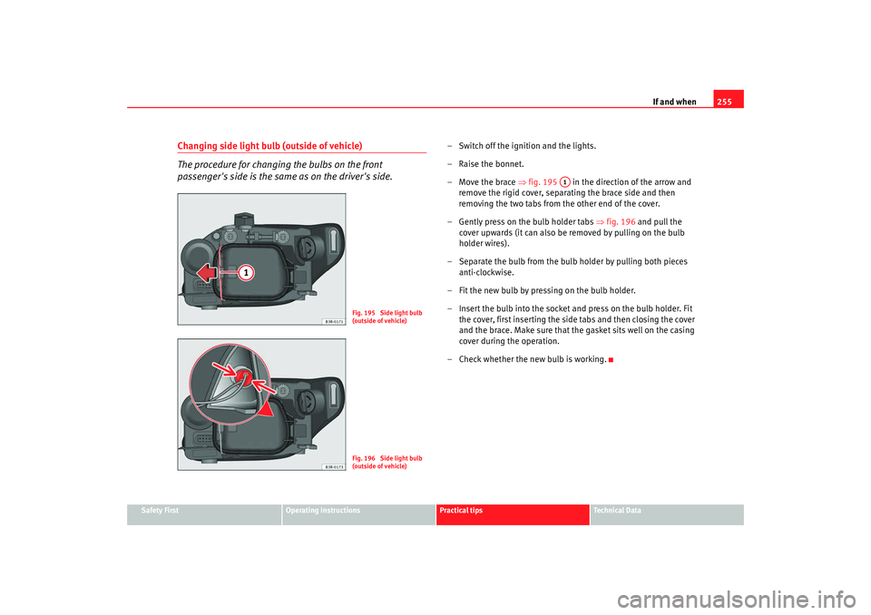
– Move the brace ⇒fig. 195 in the direction of the arrow and
remove the rigid cover, separating the brace side and then
removing the two tabs from the other end of the cover.
– Gently press on the bulb holder tabs ⇒fig. 196 and pull the
cover upwards (it can also be removed by pulling on the bulb
holder wires).
– Separate the bulb from the bulb holder by pulling both pieces anti-clockwise.
– Fit the new bulb by pressing on the bulb holder.
– Insert the bulb into the socket and press on the bulb holder. Fit the cover, first inserting the side tabs and then closing the cover
and the brace. Make sure that the gasket sits well on the casing
cover during the operation.
– Check whether the new bulb is working.
Fig. 195 Side light bulb
(outside of vehicle)Fig. 196 Side light bulb
(outside of vehicle)
A1
Exeo_EN.book Seite 255 Freitag, 17. Oktober 2008 11:24 11
Page 258 of 303
If and when
256Changing the side light bulb (inside of vehicle)
The procedure for changing the bulbs on the front
passenger's side is the same as on the driver's side.
– Switch off the ignition and the lights.
–Raise the bonnet.
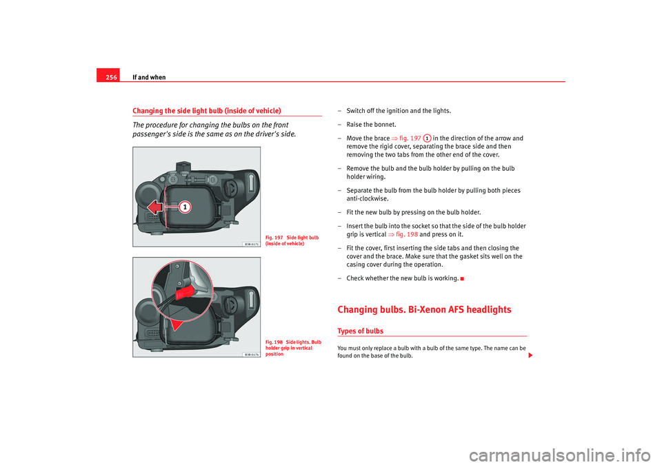
– Move the brace ⇒fig. 197 in the direction of the arrow and
remove the rigid cover, separating the brace side and then
removing the two tabs from the other end of the cover.
– Remove the bulb and the bulb holder by pulling on the bulb holder wiring.
– Separate the bulb from the bulb holder by pulling both pieces anti-clockwise.
– Fit the new bulb by pressing on the bulb holder.
– Insert the bulb into the socket so that the side of the bulb holder grip is vertical ⇒fig. 198 and press on it.
– Fit the cover, first inserting the side tabs and then closing the cover and the brace. Make sure that the gasket sits well on the
casing cover during the operation.
– Check whether the new bulb is working.Changing bulbs. Bi-Xenon AFS headlightsTypes of bulbsYou must only replace a bulb with a bulb of the same type. The name can be
found on the base of the bulb.
Fig. 197 Side light bulb
(inside of vehicle)Fig. 198 Side lights. Bulb
holder grip in vertical
position
A1
Exeo_EN.book Seite 256 Freitag, 17. Oktober 2008 11:24 11
Page 261 of 303
If and when259
Safety First
Operating instructions
Practical tips
Te c h n i c a l D a t a
Changing the DRL light bulb (day light)
The procedure for changing the bulbs on the front
passenger's side is the same as on the driver's side.– Switch off the ignition and the lights.
–Raise the bonnet.
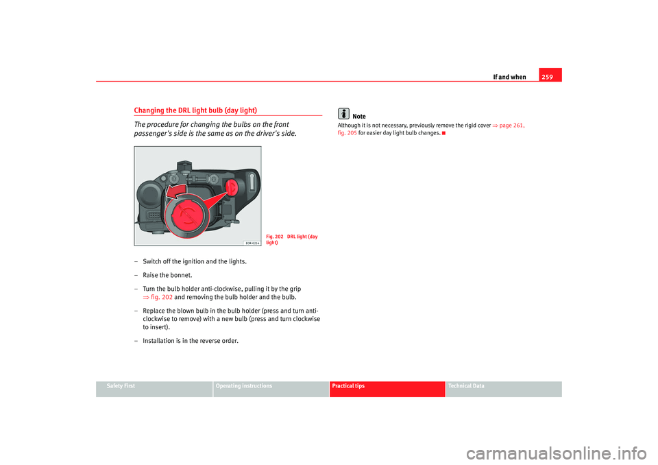
– Turn the bulb holder anti-clockwise, pulling it by the grip
⇒fig. 202 and removing the bulb holder and the bulb.
– Replace the blown bulb in the bulb holder (press and turn anti- clockwise to remove) with a new bulb (press and turn clockwise
to insert).
– Installation is in the reverse order. Note
Although it is not necessary, pr
eviously remove the rigid cover ⇒page 261,
fig. 205 for easier day light bulb changes.
Fig. 202 DRL light (day
light)
Exeo_EN.book Seite 259 Freitag, 17. Oktober 2008 11:24 11