ECU Seat Exeo 2010 Service Manual
[x] Cancel search | Manufacturer: SEAT, Model Year: 2010, Model line: Exeo, Model: Seat Exeo 2010Pages: 319, PDF Size: 9.64 MB
Page 247 of 319
Wheels and tyres245
Safety First
Operating Instructions
Practical Tips
Technical Specifications
For the sake of the environment
Old tyres must be disposed of according to the laws in the country concerned.
Note
•For technical reasons, it is not generally possible to use the wheels from
other vehicles. This can also apply to wheels of the same model. The use of
wheels or tyres which have not been approved by SEAT for use with your
model may invalidate the vehicle’s type approval for use on public roads.•If the spare tyre is not the same as the tyres that are mounted on the
vehicle - for example with winter tyres - you should only use the spare tyre for
a short period of time and drive with extra care. Refit the normal road wheel
as soon as possible.Wheel bolts
Wheel bolts must be tightened to the correct torque.The design of wheel bolts is matched to the rims. If different wheel rims are
fitted, the correct wheel bolts with the right length and correctly shaped bolt
heads must be used. This ensures that wheels are fitted securely and that the
brake system functions correctly.
In certain circumstances, you should not use wheel bolts from a different
vehicle, even if it is the same model ⇒page 218.
After the wheels have been changed, the tightening torque of the wheel bolts
s ho uld b e ch ecke d as so on as possi ble wi th a to rq ue wre nch. ⇒ The tight-
ening torque for steel and alloy wheels is 120 Nm.
WARNING
If the wheel bolts are not tightened correctly, the wheel could become
loose while driving. Risk of accident.•The wheel bolts must be clean and turn easily. Never apply grease or oil
to them.•Use only wheel bolts which belong to the wheel.•If the torque of the wheel bolts is too low, they could loosen whilst the
vehicle is in motion. Risk of accident! If the tightening torque is too high,
the wheel bolts and threads can be damaged.Caution
The prescribed tightening torque for wheel bolts for steel and alloy wheels is
120 Nm.Winter tyres
Winter tyres will improve the vehicles handling on snow and
ice.In winter conditions winter tyres will considerably improve the vehicle’s
handling. The design of summer tyre s (width, rubber compound, tread
pattern) gives less grip on ice and snow.
Winter tyres must be inflated to a pressure 0.2 bar higher than the pressures
specified for summer tyres (see sticker on tank flap).
Winter tyres must be fitted on all four wheels.
Information on permitted winter tyre sizes can be found in the vehicle’s regis-
tration documents. Use only radial winter tyres. All tyre sizes listed in the
vehicle documentation also apply to winter tyres.
exeo_EN.book Seite 245 Montag, 30. August 2010 4:45 16
Page 250 of 319
If and when
248Tyre mobility system
The tyre mobility system is stor ed under the floor panel in the
luggage compartment.– Take hold of the handle and fold back the floor panel in the
luggage compartment.
– Take out the tyre mobility system.Your vehicle is equipped with a Tyre Mobility System in case of a puncture.
The tyre mobility system consists of a container with sealing compound and
a compressor to generate the required tyre pressure.
Instructions for using the sealant compound and the compressor are
included with the sealant can.
Spare steel rim wheel
The spare steel rim wheel is carried in the wheel well under
the floor panel in the luggage compartment. It is only
intended for temporary use over short distances.Taking out the spare wheel
–Turn the plastic knob ⇒fig. 178 anti-clockwise.
– Take out the spare wheel.
Securing the defective wheel in the spare wheel well
– Place wheel in spare wheel well in the luggage compartment.
– Secure the wheel by turning plastic knob clockwise.
– Replace the floor panel before closing the tailgate.
Fig. 177 Tyre Mobility
System under floor panel
in luggage compartment
Fig. 178 Spare steel rim
wheel
exeo_EN.book Seite 248 Montag, 30. August 2010 4:45 16
Page 252 of 319
If and when
250
NotePlease observe legal requirements when doing so.Changing a wheel
Change the wheel as described below.– Remove the wheel cover.
–Loosen the wheel bolts ⇒ page 251.
– Raise the vehicle with the jack ⇒page 252.
– Ta k e o f f the wheel with the flat tyre and then put on the spare
wheel ⇒page 253.
– Lower the vehicle.
– Tighten the wheel bolts firmly in diagonal sequence with the box
spanner ⇒page 251.
–Replace the cover.After changing a wheel
After changing the wheel, there are still tasks to complete.– Place the wheel with the defective tyre in the spare wheel well
and secure it.
– Put the tools and jack back in the luggage compartment. –The
inflation pressure of the newly fitted spare tyre must be
checked as soon as possible.
–Have the tightening torque of the wheel bolts checked as soon
as possible with a torque wrench. It must be 120 Nm (always
when cold)
–Have the flat tyre replaced as quickly as possible.
Note
•If you notice that the wheel bolts are rusty and difficult to turn when
changing a wheel, they must be replaced before having the tightening torque
checked.•For your safety, drive at moderate speeds until the wheel bolt tightening
torque has been checked.
exeo_EN.book Seite 250 Montag, 30. August 2010 4:45 16
Page 276 of 319
If and when
274Removing the tail light
To change the bulbs you must remove the tail light assembly.
Removing the light requires a certain degree of practical skill.
A special retaining screw is used to secure and guide the tail light.
– Check which of the bulbs is defective.
–Open the tailgate.
– Take the screwdriver out of the vehicle’s tool kit ⇒page 247.
– Use the flat-blade side of th e reversible screwdriver insert.
– Prise open the cover at the slot with the screwdriver ⇒ fig. 210
.
– Use a screwdriver to loosen the screw (arrow) located behind the cover.
– Gradually ease the tail light out of the housing ( ⇒fig. 211 posi-
tions and ) by pulling alternately in positions and .
– Remove the bulb holder ⇒page 275.
CautionTake care when removing the tail light to make sure there is no damage to the
paintwork or any of its components.
Note
Make sure you have a soft cloth ready to place under the glass on the tail
light, to avoid any scratches.
Fig. 210 Luggage
compartment: Location of
the bolt securing the tail
light unitFig. 211 Removing tail
light from side panel
A1
A2
A3
A4
A1
A2
exeo_EN.book Seite 274 Montag, 30. August 2010 4:45 16
Page 277 of 319
If and when275
Safety First
Operating Instructions
Practical Tips
Technical Specifications
Remove the bulb holder
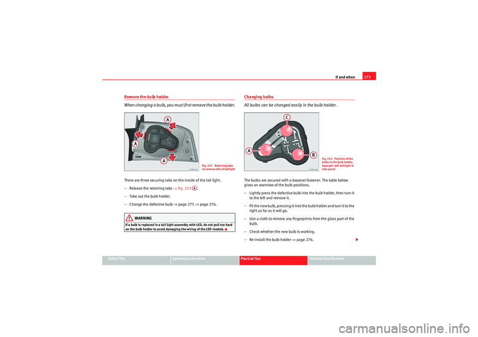
When changing a bulb, you must first remove the bulb holder.There are three securing tabs on the inside of the tail light.
– Release the retaining tabs ⇒ fig. 212 .
– Take out the bulb holder.
– Change the defective bulb ⇒page 275 ⇒page 276.
WARNING
If a bulb is replaced in a tail light assembly with LED, do not pull too hard
on the bulb holder to avoid damaging the wiring of the LED module.
Changing bulbs
All bulbs can be changed easily in the bulb holder.The bulbs are secured with a bayonet fastener. The table below
gives an overview of the bulb positions.
– Lightly press the defective bulb into the bulb holder, then turn it
to the left and remove it.
– Fit the new bulb, pressing it into the bulb holder and turn it to the right as far as it will go.
– Use a cloth to remove any fingerp rints from the glass part of the
bulb.
– Check whether the new bulb is working.
– Re-install the bulb holder ⇒page 276.
Fig. 212 Retaining tabs
on reverse side of tail light
AA
Fig. 213 Position of the
bulbs in the bulb holder.
Example: Left tail light in
side panel
exeo_EN.book Seite 275 Montag, 30. August 2010 4:45 16
Page 278 of 319
If and when
276Position of the bulbsChanging bulbs. LED lamps
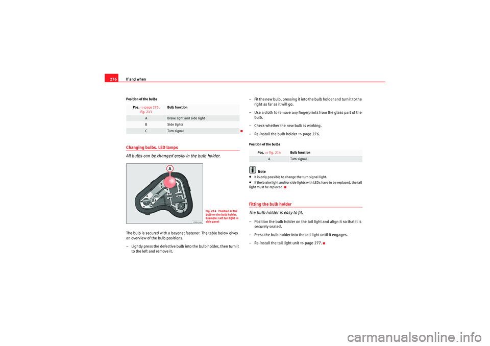
All bulbs can be changed easily in the bulb holder.The bulb is secured with a bayonet fastener. The table below gives
an overview of the bulb positions.
– Lightly press the defective bulb into the bulb holder, then turn it
to the left and remove it. – Fit the new bulb, pressing it into the bulb holder and turn it to the
right as far as it will go.
– Use a cloth to remove any fingerp rints from the glass part of the
bulb.
– Check whether the new bulb is working.
– Re-install the bulb holder ⇒page 276.
Position of the bulbs
Note
•It is only possible to change the turn signal light.•If the brake light and/or side lights with LEDs have to be replaced, the tail
light must be replaced.Fitting the bulb holder
The bulb holder is easy to fit.– Position the bulb holder on the tail light and align it so that it is securely seated.
– Press the bulb holder into the tail light until it engages.
– Re-install the tail light unit ⇒page 277.
Pos. ⇒ page 275,
fig. 213
Bulb function
A
Brake light and side light
B
Side lights
C
Turn signal
Fig. 214 Position of the
bulb on the bulb holder.
Example: Left tail light in
side panel
Pos. ⇒ fig. 214
Bulb function
A
Turn signal
exeo_EN.book Seite 276 Montag, 30. August 2010 4:45 16
Page 279 of 319
If and when277
Safety First
Operating Instructions
Practical Tips
Technical Specifications
Fitting the tail light unit
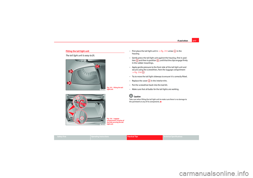
The tail light unit is easy to fit.
– First place the tail light unit in ⇒fig. 215 arrow in the
housing.
– Gently press the tail light unit against the housing, first in posi- tion and then in position , until that the clips engage firmly
in the rubber mountings.
– Apply gentle pressure to the front side of the tail light unit and secure using the screwdriver, from the luggage compartment
⇒fig. 216 .
– Try to move the tail light sideways to ensure it is correctly fitted.
– Replace the cover in the interior trim.
– Put the screwdriver back into the tool kit.
– Make sure that all bulbs for the tail lights are working.
CautionTake care when fitting the tail light unit to make sure there is no damage to
the paintwork or any of its components.
Fig. 215 Fitting the tail
light unitFig. 216 Luggage
compartment: Location of
the bolt securing the tail
light unit
A1
A2
A3
A1
A2
exeo_EN.book Seite 277 Montag, 30. August 2010 4:45 16
Page 282 of 319
If and when
280Changing bulbs
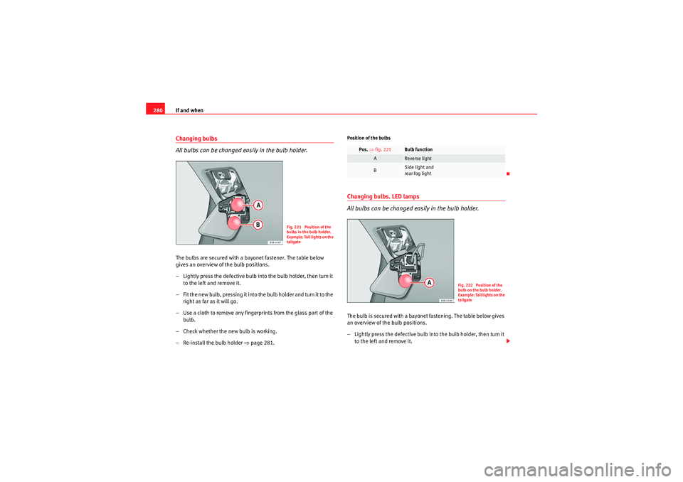
All bulbs can be changed easily in the bulb holder.The bulbs are secured with a bayonet fastener. The table below
gives an overview of the bulb positions.
– Lightly press the defective bulb into the bulb holder, then turn it
to the left and remove it.
– Fit the new bulb, pressing it into the bulb holder and turn it to the right as far as it will go.
– Use a cloth to remove any fingerp rints from the glass part of the
bulb.
– Check whether the new bulb is working.
– Re-install the bulb holder ⇒ page 281.
Position of the bulbsChanging bulbs. LED lamps
All bulbs can be changed easily in the bulb holder.The bulb is secured with a bayonet fastening. The table below gives
an overview of the bulb positions.
– Lightly press the defective bulb into the bulb holder, then turn it
to the left and remove it.
Fig. 221 Position of the
bulbs in the bulb holder.
Example: Tail lights on the
tailgate
Pos. ⇒ fig. 221
Bulb function
A
Reverse light
B
Side light and
rear fog light
Fig. 222 Position of the
bulb on the bulb holder.
E x a m p l e : Ta i l l i g h t s o n t h e
tailgate
exeo_EN.book Seite 280 Montag, 30. August 2010 4:45 16
Page 283 of 319
If and when281
Safety First
Operating Instructions
Practical Tips
Technical Specifications
– Fit the new bulb, pressing it into the bulb holder and turn it to the
right as far as it will go.
– Use a cloth to remove any fingerp rints from the glass part of the
bulb.
– Check whether the new bulb is working.
– Re-install the bulb holder ⇒page 281.Position of the bulbsFitting the bulb holder
The bulb holder is easy to fit.– Check that the seal is seated correctly on the bulb holder.
– Position the bulb holder on the tail light and align it so that it is
securely seated.
– Press the bulb holder into the tail light until it engages.
– Fit the cover back in the inte rior trim so that it engages.
– Put the screwdriver back into the tool kit.
– Make sure that all bulbs for the tail lights are working.
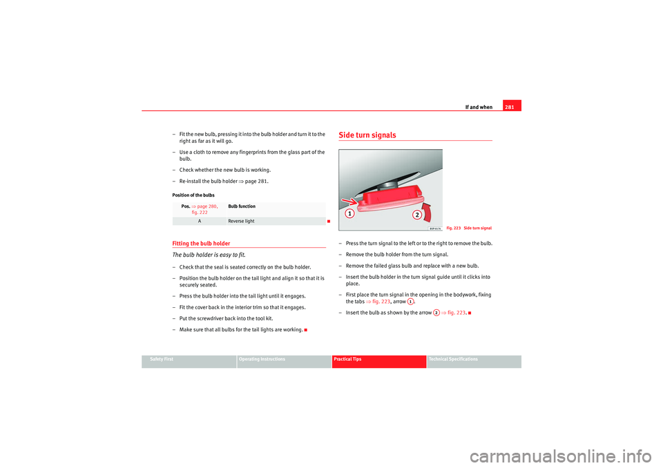
Side turn signals– Press the turn signal to the left or to the right to remove the bulb.
– Remove the bulb holder from the turn signal.
– Remove the failed glass bulb and replace with a new bulb.
– Insert the bulb holder in the turn signal guide until it clicks into place.
– First place the turn signal in the opening in the bodywork, fixing the tabs ⇒ fig. 223, arrow .
– Insert the bulb as shown by the arrow ⇒fig. 223 .
Pos. ⇒ page 280,
fig. 222
Bulb function
A
Reverse light
Fig. 223 Side turn signal
A1
A2
exeo_EN.book Seite 281 Montag, 30. August 2010 4:45 16
Page 310 of 319
Index
308Bonnet . . . . . . . . . . . . . . . . . . . . . . . . . . . . . . . . 223
Closing . . . . . . . . . . . . . . . . . . . . . . . . . . . . . 225
Opening . . . . . . . . . . . . . . . . . . . . . . . . . . . . 223
Releasing . . . . . . . . . . . . . . . . . . . . . . . . . . . 223
Brake light Failure control . . . . . . . . . . . . . . . . . . . . . . . . 80
Brake pads . . . . . . . . . . . . . . . . . . . . . . . . . . . . . 192
Brake servo . . . . . . . . . . . . . . . . . . . . . . . . . . . . 192
Brake system Brake servo . . . . . . . . . . . . . . . . . . . . . . . . . 189
Brakes . . . . . . . . . . . . . . . . . . . . . . . . . . . . . 189
Malfunction . . . . . . . . . . . . . . . . . . . . . . . . . . 77
Brakes . . . . . . . . . . . . . . . . . . . . . . . . . . . . . . . . 192 Brake assist system . . . . . . . . . . . . . . . . . . 187
Brake fluid . . . . . . . . . . . . . . . . . . . . . . . . . . 233
Worn brake pads . . . . . . . . . . . . . . . . . . . . . . 81
Braking distance . . . . . . . . . . . . . . . . . . . . . . . . 192
Bulb change General notes . . . . . . . . . . . . . . . . . . . . . . . 260CCatalytic converter . . . . . . . . . . . . . . . . . . . . . . 193
Central locking . . . . . . . . . . . . . . . . . . . . . . . . . . 98
Manual locking . . . . . . . . . . . . . . . . . . . . . . 102
Sunroof: opening and closing . . . . . . . . . . 112
Central locking system Anti-theft security system . . . . . . . . . . . . . . 100
Locking . . . . . . . . . . . . . . . . . . . . . . . . . . . . . 99
Locking and unlocking the vehicle from inside100 Opening and closing the windows . . . . . . 110
Security central locking . . . . . . . . . . . . . . . 101
Switch on the driver door . . . . . . . . . . . . . . 100
Tailgate . . . . . . . . . . . . . . . . . . . . . . . . . . . . 103
Unlocking . . . . . . . . . . . . . . . . . . . . . . . . . . . 99
Cetane number . . . . . . . . . . . . . . . . . . . . . . . . . 222
Changing tail light bulbs . . . . . . . . . . . . . . . . . 273
Changing the main headlight bulb Main headlight . . . . . . . . . . . . . . . . . . . . . . 264
Changing the main headlight bulbs Dipped beam headlight . . . . . . . . . . . . . . . 265
Changing the tail lights Luggage compartment lights . . . . . . . . . . . 282
Changing windscreen wiper blades . . . . . . . . . 232
Chassis number . . . . . . . . . . . . . . . . . . . . . . . . 292
Child safety . . . . . . . . . . . . . . . . . . . . . . . . . . . . . 46
Child safety seat ISOFIX system . . . . . . . . . . . . . . . . . . . . . . . . 52
Child seat . . . . . . . . . . . . . . . . . . . . . . . . . . . . . . . 48 Categorisation in groups . . . . . . . . . . . . . . . 48
Group 1 . . . . . . . . . . . . . . . . . . . . . . . . . . . . . 49
Group 2 . . . . . . . . . . . . . . . . . . . . . . . . . . . . . 49
Group 3 . . . . . . . . . . . . . . . . . . . . . . . . . . . . . 49
Groups 0 and 0+ . . . . . . . . . . . . . . . . . . . . . . 48
Safety notes . . . . . . . . . . . . . . . . . . . . . . . . . . 46
Securing . . . . . . . . . . . . . . . . . . . . . . . . . . . . . 51
Child seats on the front passenger seat . . . . . . . . . . . . . 29
Childproof lock Rear doors . . . . . . . . . . . . . . . . . . . . . . . . . . 104
Cigarette lighter . . . . . . . . . . . . . . . . . . . . . . . . 149 Cleaning alloy wheel rims . . . . . . . . . . . . . . . . 214
Cleaning chrome . . . . . . . . . . . . . . . . . . . . . . . . 213
Cleaning engine compartment . . . . . . . . . . . . . 215
Cleaning steel wheel rims . . . . . . . . . . . . . . . . 214
Cleaning windows . . . . . . . . . . . . . . . . . . . . . . . 212
Clock, setting . . . . . . . . . . . . . . . . . . . . . . . . . . . 61
Cloth seat covers cleaning . . . . . . . . . . . . . . . . 216
Coat hooks . . . . . . . . . . . . . . . . . . . . . . . . . . . . 154
Cockpit . . . . . . . . . . . . . . . . . . . . . . . . . . . . . . . . . 57
Overview . . . . . . . . . . . . . . . . . . . . . . . . . . . . 57
Compartments . . . . . . . . . . . . . . . . . . . . . . . . . . 153 In the door trim . . . . . . . . . . . . . . . . . . . . . . 154
In the front seats . . . . . . . . . . . . . . . . . . . . . 155
Coolant Checking the level . . . . . . . . . . . . . . . . . . . 229
Coolant fluid Antifreeze . . . . . . . . . . . . . . . . . . . . . . . . . . 228
Coolant fluid additive . . . . . . . . . . . . . . . . . 228
Topping up . . . . . . . . . . . . . . . . . . . . . . . . . 229
Cooling system Coolant temperature gauge . . . . . . . . . . . . . 60
Malfunction . . . . . . . . . . . . . . . . . . . . . . . . . . 78
Correct adjustment of front seat head restraints . . 13
Correct adjustment of rear seat head restraints In-use and non-use positions . . . . . . . . . . . 14
Correct sitting position Front passenger . . . . . . . . . . . . . . . . . . . . . . 12
Incorrect sitting position . . . . . . . . . . . . . . . 14
Cruise control . . . . . . . . . . . . . . . . . . . . . . . . . . 174
exeo_EN.book Seite 308 Montag, 30. August 2010 4:45 16