ignition Seat Exeo 2011 Workshop Manual
[x] Cancel search | Manufacturer: SEAT, Model Year: 2011, Model line: Exeo, Model: Seat Exeo 2011Pages: 313, PDF Size: 5.02 MB
Page 128 of 313

126Lights and visibility
Visibility
Heated rear window
The rear window heating clears the rear window of conden-
sation.
Fig. 97 Switch for heat-
ed rear window
– Press button
to switch the rear window heating on or off
⇒ fig. 97.
The heated rear window only works when the ignition is switched on. An in-
dicator lamp on the button lights up when the rear window heater is switch-
ed on.
The heated rear window switches off automatically after about 10 minutes if
the outside temperature is above 0 °C.
Depending on the outside temperature, the exterior mirrors are also heated
while the heated rear window is turned on. The exterior mirror heating is not activated in temperatures above approxi-
mately 20 °C.
For the sake of the environment
Switch off the heated rear window as soon as the rear window has demis-
ted. By saving electrical power you can also save fuel.
Sun visors
The sun visors can improve visibility and contribute to safe-
ty.
Fig. 98 Sun visor
The sun visors 1
for the driver and the front passenger can be pulled out of
their mountings in the centre of the vehicle and turned towards the doors
⇒ fig. 98.
The vanity mirrors in the sun visor have covers. On opening the cover 2
,
the mirror light* located in the headliner is automatically switched on. The
Page 130 of 313
128Lights and visibility
Note
● An overload cut-out may be triggered if the sun blind for the rear window
is operated repeatedly. There will then be a short delay before the blind can
be operated again.
● As the material of the sun blind is less flexible at low temperatures, the
electric actuator is switched off when the outside temperature is below
-5 °C. The sun blind can only be operated when the temperature inside the
car rises above this level.
Windscreen wipers
Windscreen wipers
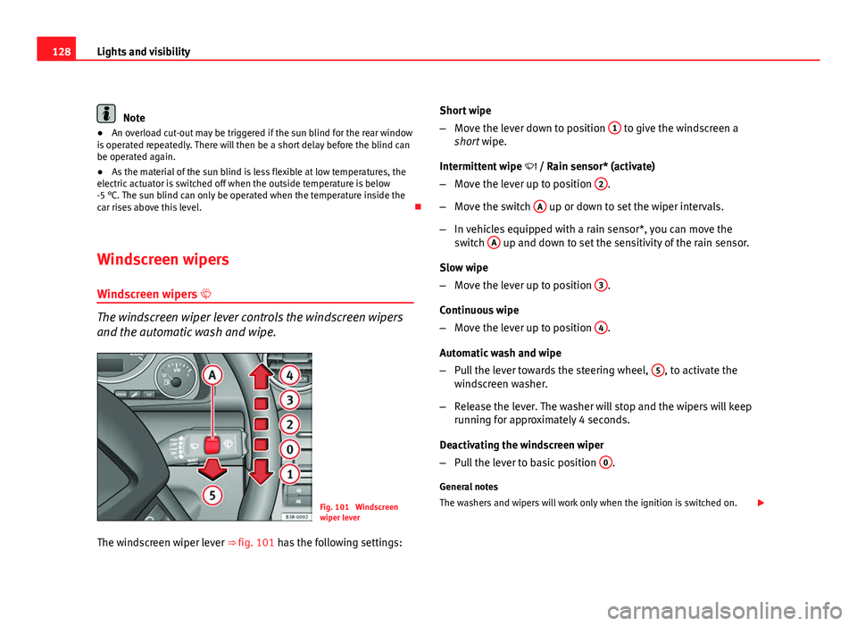
The windscreen wiper lever controls the windscreen wipers
and the automatic wash and wipe.
Fig. 101 Windscreen
wiper lever
The windscreen wiper lever ⇒ fig. 101 has the following settings: Short wipe
–
Move the lever down to position 1
to give the windscreen a
short wipe.
Intermittent wipe / Rain sensor* (activate)
– Move the lever up to position 2
.
– Move the switch A
up or down to set the wiper intervals.
– In vehicles equipped with a rain sensor*, you can move the
switch A
up and down to set the sensitivity of the rain sensor.
Slow wipe
– Move the lever up to position 3
.
Continuous wipe
– Move the lever up to position 4
.
Automatic wash and wipe
– Pull the lever towards the steering wheel, 5
, to activate the
windscreen washer.
– Release the lever. The washer will stop and the wipers will keep
running for approximately 4 seconds.
Deactivating the windscreen wiper
– Pull the lever to basic position 0
.
General notes
The washers and wipers will work only when the ignition is switched on.
Page 131 of 313
129
Lights and visibility
If you stop briefly, e.g. at traffic lights, the wiper speed will automatically be
reduced. The rain sensor* will automatically be set to the intermittent wipe
function.
The windscreen washer jets are heated when the ignition is switched on.
The wiper intervals in the intermittent wipe setting are also varied automati-
cally according to the road speed (in addition to the manual delay setting).
When the lights are switched on you should only pull the lever briefly to
wash the windscreen, otherwise the headlight washers* will also be ena-
bled. This will use an unnecessary amount of fluid from the reservoir.
Rain sensor
The rain sensor* will only function in the intermittent wipe position. The in-
termittent wipe function is enabled automatically when it starts to rain.
If the windscreen wiper lever was in the intermittent wipe position when the
ignition was off, the rain sensor will not activate until you reach a speed of 6
km/h.
Use switch A
to set the sensitivity of the rain sensor*.
If you have selected a high sensitivity level for the rain sensor the wind-
screen wipers will react sooner to any moisture on the windscreen.
The wiper intervals in the intermittent wipe setting are also varied automati-
cally according to the road speed (in addition to the sensitivity setting).
WARNING
● For correct visibility and safe driving, the wiper must be in perfect
condition ⇒ page 210. Failure to do so could result in an accident.
● The rain sensor* is only intended to assist the driver. The driver is
still obliged to manually operate the windscreen wipers as required de-
pending on visibility.
● Do not use water-repellent coatings on the windscreen. In bad visibili-
ty conditions such as light rain, low sun or when driving at night, these
coatings can cause increased dazzle, which is a serious safety hazard.
Such coatings can also cause the wiper blades to make noise.
CAUTION
● In the event of frost, check that the wiper blade has not frozen before
activating the windscreen wipers. Should the windscreen wiper system be
enabled when the blade is frozen, this could damage it or even the wind-
screen wiper system motor.
● Make sure you switch off the windscreen wiper system (lever in position
0) before you use an automatic car wash. This will avoid inadvertent trigger-
ing of the wipers and possible damage to the wiper system.
Note
● Check that the washer fluid reservoir is full before starting a long jour-
ney. Fill the reservoir ⇒ page 228.
● Worn or dirty wiper blades can cause smearing on the glass which can
also impair the effectiveness of the rain sensor*. Check the condition of
windscreen wiper blades at regular intervals.
Safety FirstOperating InstructionsPractical TipsTechnical Specifications
Page 133 of 313

131
Lights and visibility
Switching off the anti-dazzle function
– Press button A
⇒ fig. 103. Indicator lamp B goes off.
Switching on the anti-dazzle function
– Press button A
⇒ fig. 103. Indicator lamp B turns on.
Anti-dazzle function
The anti-dazzle function is activated every time the ignition is switched on.
The green indicator lamp lights up in the mirror housing.
When the anti-dazzle function is enabled, the interior mirror will darken au-
tomatically according to the amount of light it receives. The anti-dazzle
function is disabled if:
● the interior lighting is switched on
● reverse gear is engaged
Sensors for automatic headlights*
When the light switch is set to the AUTO position, the dipped beam head-
lights are switched on and off automatically according to the ambient light
level with the aid of the sensors located in the interior mirror ⇒ page 116.
WARNING
Electrolyte fluid can leak from a broken mirror. This fluid can cause irrita-
tion to the skin, eyes and respiratory organs. Wash thoroughly with clean
water should you come into contact with this fluid. Seek medical assis-
tance if needed!
CAUTION
Electrolyte fluid leaking from a broken mirror can cause damage to plastic
surfaces. Use a sponge or similar to remove the fluid as soon as possible.
Note
● The interior mirror automatic anti-dazzle function* will only work proper-
ly if the sun blind* for the rear window is retracted and if there are no other
objects preventing light from reaching the mirror.
● If you have to stick any type of sticker on the windscreen, do not do so in
front of the sensors. Doing so could prevent the automatic headlight or anti-
dazzle function from working correctly or even from working at all.
Exterior mirrors
The exterior mirrors are adjusted electrically.
Fig. 104 Detailed view of
the armrest: Adjuster
knob
Adjusting the exterior mirrors
– Turn the adjuster knob to position ⇒ fig. 104 L
(left exterior
mirror) or position R (right exterior mirror).
– Move the knob as required to adjust the exterior mirror for a
good view behind you.
Safety FirstOperating InstructionsPractical TipsTechnical Specifications
Page 138 of 313
136Seats and storage compartments
Controls
Seat adjustment
Backrest adjustment
Lumbar support*
WARNING
● The electrical seat adjustment also works when the ignition is off or
when the key is not in the ignition. To avoid accidental injuries, never
leave children unattended in the vehicle.
● For safety reasons, the seat must only be adjusted when the vehicle
is at a standstill. Failure to do so could result in an accident.
● Be careful when adjusting the seat height. Injuries can be caused if
the seat height is adjusted without due care and attention.
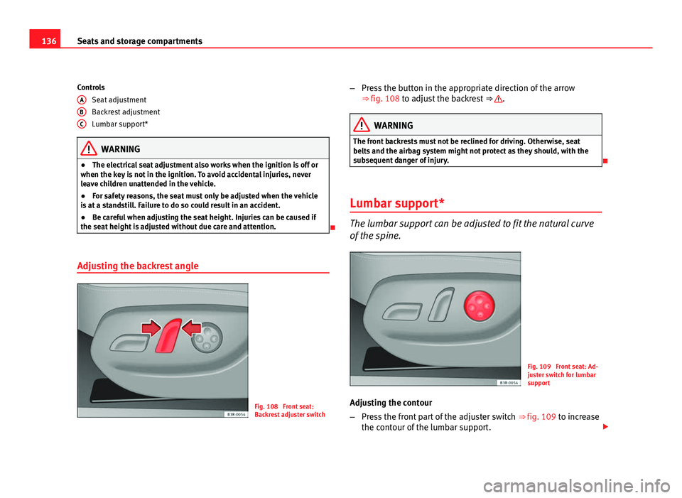
Adjusting the backrest angle
Fig. 108 Front seat:
Backrest adjuster switch
A
BC
–
Press the button in the appropriate direction of the arrow
⇒ fig. 108 to adjust the backrest ⇒ .
WARNING
The front backrests must not be reclined for driving. Otherwise, seat
belts and the airbag system might not protect as they should, with the
subsequent danger of injury.
Lumbar support*
The lumbar support can be adjusted to fit the natural curve
of the spine.
Fig. 109 Front seat: Ad-
juster switch for lumbar
support
Adjusting the contour
– Press the front part of the adjuster switch ⇒ fig. 109 to increase
the contour of the lumbar support.
Page 151 of 313

149
Seats and storage compartments
Using the cigarette lighter
– Press in the cigarette lighter button.
– Wait for the lighter to pop out slightly.
– Pull out the cigarette lighter immediately.
– Use the glowing heater element of the cigarette lighter to light
your cigarette.
– Put the cigarette lighter back in its socket.
Operating the socket
– Take out the cigarette lighter.
– Insert the plug of the electrical appliance into the cigarette
lighter socket.
The cigarette lighter ⇒ fig. 124 employs a standard 12 volt socket, which can also be used as a power source for electrical appliances. The applian-
ces connected to the socket must not exceed a power rating of 100 W.
WARNING
● Be careful when using the electric cigarette lighter. Carelessness or
negligence when using the cigarette lighter can cause burns.
● The lighter will only work when the ignition is switched on.
● The electrical sockets and, therefore, any appliances connected to
them will only work when the ignition is switched on.
CAUTION
Always use the correct type of plugs to avoid damaging the sockets.
Note
The use of electrical appliances with the engine switched off will cause a
battery discharge.
Power socket*
Electrical equipment can be connected to the 12 volt socket.
Fig. 125 Detailed view of
the side trim in the lug-
gage compartment: 12
volt socket
– Lift the power socket cover ⇒ fig. 125.
– Insert the plug of the electrical appliance into the socket.
Electrical equipment can be connected to the 12 volt socket. The appliances
connected to the socket must not exceed a power rating of 100 W.
Safety FirstOperating InstructionsPractical TipsTechnical Specifications
Page 152 of 313
150Seats and storage compartments
WARNING
The electrical sockets and, therefore, any appliances connected to them
will only work when the ignition is switched on.
CAUTION
Always use the correct type of plugs to avoid damaging the sockets.
Note
The use of electrical appliances with the engine switched off will cause a
battery discharge.
230 volt socket for Europlug*
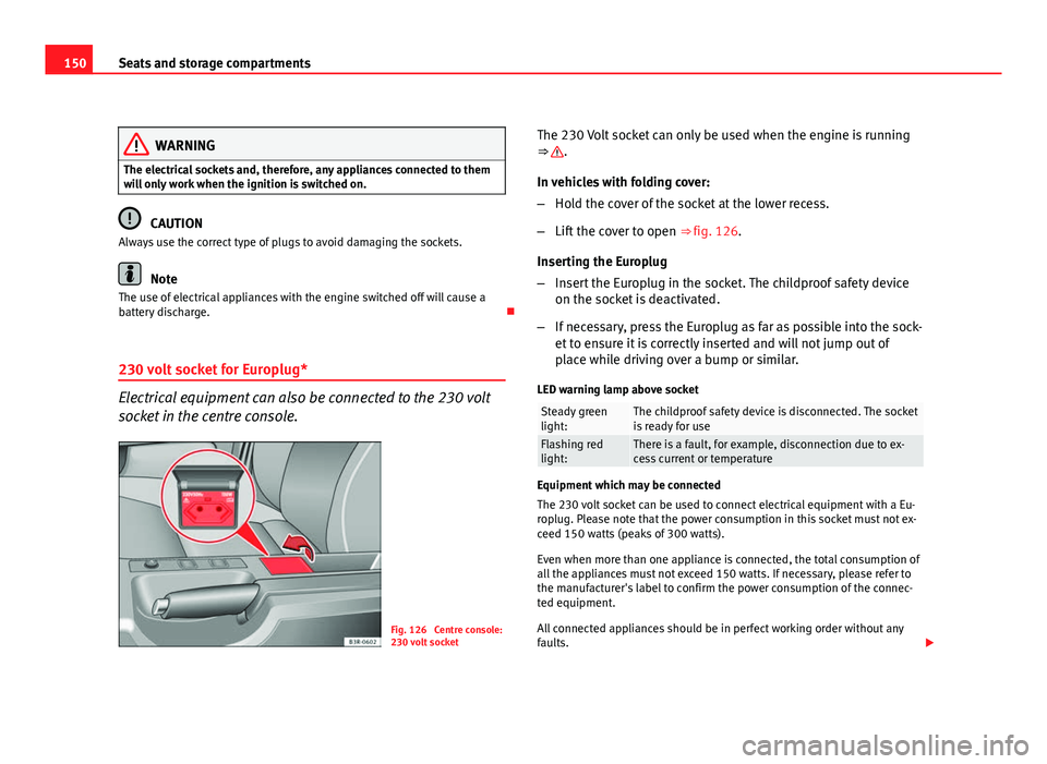
Electrical equipment can also be connected to the 230 volt
socket in the centre console.
Fig. 126 Centre console:
230 volt socket The 230 Volt socket can only be used when the engine is running
⇒
.
In vehicles with folding cover:
– Hold the cover of the socket at the lower recess.
– Lift the cover to open ⇒ fig. 126.
Inserting the Europlug
– Insert the Europlug in the socket. The childproof safety device
on the socket is deactivated.
– If necessary, press the Europlug as far as possible into the sock-
et to ensure it is correctly inserted and will not jump out of
place while driving over a bump or similar.
LED warning lamp above socket
Steady green
light:The childproof safety device is disconnected. The socket
is ready for use
Flashing red
light:There is a fault, for example, disconnection due to ex-
cess current or temperature
Equipment which may be connected
The 230 volt socket can be used to connect electrical equipment with a Eu-
roplug. Please note that the power consumption in this socket must not ex-
ceed 150 watts (peaks of 300 watts).
Even when more than one appliance is connected, the total consumption of
all the appliances must not exceed 150 watts. If necessary, please refer to
the manufacturer's label to confirm the power consumption of the connec-
ted equipment.
All connected appliances should be in perfect working order without any
faults.
Page 162 of 313

160Air conditioning
Note
If the diode on the ECON button continues to light up when the ECON mode
has been switched off (i.e. the air conditioner has been switched on) this is
due to a defect in one of the air conditioner components. If a malfunction
should occur, please contact a specialised workshop.
Air recirculation: automatic activation*
If the outside air is polluted by diesel and petrol emissions,
an air quality sensor in the vehicle will automatically switch
on the air recirculation.
Fig. 131 Button for auto-
matic air recirculation
Activating air recirculation mode
– Press the button
⇒ fig. 131.
Deactivating air recirculation mode
– Press the
button again or –
Press the AUTO
button or
– Press button
.
The automatic air recirculation mode should normally be left switched on at
all times.
The system is ready to operate approx. 30 seconds after the engine ignition
key has been turned. During this initial period, fresh air is fed into the vehi-
cle.
If the air purity sensor in the air conditioner detects a certain concentration
of fumes in the outside air, the control unit will either pass the incoming air
through the pollution filter or automatically switch on the air recirculation. If
there is a high concentration of pollution in the outside air, the air condi-
tioner automatically switches to air recirculation and the supply of air from
the outside is cut off. As soon as the level of pollution decreases, air is fed
into the vehicle from the outside again.
The automatic air recirculation operates for a maximum period of 12 mi-
nutes. If the windows mist up when the automatic air recirculation is on,
press the
button immediately.
The automatic air recirculation switches itself off under certain circumstan-
ces (for instance if
or is selected). In “ECON” and at temperatures
lower than approx. 8 °C below zero, the automatic air recirculation mode is
limited to 12 seconds.
Page 165 of 313
163
Air conditioning
Air directed to windows
This setting directs all the air to outlets 1 and 2. Unlike in setting , the
volume of air delivery remains the same.
Air to the driver/front passenger
All the air comes from outlets 3 and 4 in the dash panel and from the rear of
the centre console.
Air to the footwells
Most of the air emerges from outlets 5 and the outlets under the front seats.
Some of the air will also be issued from outlets 3 and 4.
Note
In all of the above air distribution settings, a small amount of air will still
come from the other outlets.
Economical use of the air conditioner
Economical use of the air conditioner will help save fuel.
Engine power is reduced and fuel consumption increases when the
air conditioner is in cooling mode. To ensure that the system is on-
ly switched on when it is really necessary, please note the follow-
ing points:
– Select ECON mode if you wish to save fuel.
– Select ECON mode if you decide to open the windows or sun-
roof* while driving.
– If the vehicle has heated up after standing in the sun, open the
windows and doors for a short time to cool the vehicle.
For the sake of the environment
By saving fuel you also reduce the amount of pollutants emitted from your
vehicle.
Key settings
When the ignition is switched on, the air conditioner set-
tings assigned to the key are selected automatically.
The air conditioner settings selected are automatically stored and assigned
to the key in use. When the vehicle is started, the air conditioner automati-
cally selects the settings assigned to the key. Hence, every driver automati-
cally obtains his/her preferred settings without having to select them man-
ually.
Note
Should another driver use the key and enter other settings, the previous
settings will be deleted.
Solar-powered blower/sunroof*
If the vehicle is parked in sufficiently strong sunlight, the
blower will operate in solar-powered mode when the igni-
tion is switched off.
After the ignition is switched off, the blower is supplied with electrical pow-
er from the sunroof. Please ensure that outlets 3 and 4 are open ⇒ fig. 132
to ensure the best possible ventilation.
The blower only works when the sunroof is closed or tilted open at the rear.
Safety FirstOperating InstructionsPractical TipsTechnical Specifications
Page 168 of 313
166Driving
The Electronic Stability Programme (ESP) contains the electronic differential
lock (EDL) and the traction control system (TCS). The ESP function works to-
gether with the ABS. If a fault in the ABS occurs, both warning lamps light
up, but if the ESP fails, only the ESP warning lamp lights up.
The ESP is started automatically when the engine is started.
The ESP switch deactivates both TCS and ESP functions. The ESP, in spite of
being deactivated, will always self-connect when necessary if brakes are be-
ing used.
The TCS can be deactivated when in cases where wheel sliding is desirable.
For example:
● When driving with snow chains.
● When driving in deep snow or on loose surfaces.
● When the vehicle is stuck, to rock it backwards and forwards.
Next, the button should be pressed to reactivate the TCS.
When does the lamp light up or flash
●
On switching the ignition on, it lights up for about two seconds to carry
out a function control.
● The warning lamp will start flashing when the vehicle is moving if the
ESP or the TCS is activated.
● It will light up continuously if there is a malfunction in the ESP.
WARNING
● The Electronic Stability Programme (ESP) cannot defy the laws of
physics. This should be kept in mind, particularly on slippery and wet
roads and when towing a trailer.
● Always adapt your driving style to suit the condition of the roads and
the traffic situation. Do not let the extra safety afforded by ESP tempt you
into taking any risks when driving, as this can cause accidents.
● Please refer to the corresponding warning notes on ESP in
⇒ page 184, Intelligent technology.
Ignition lock Ignition key positions
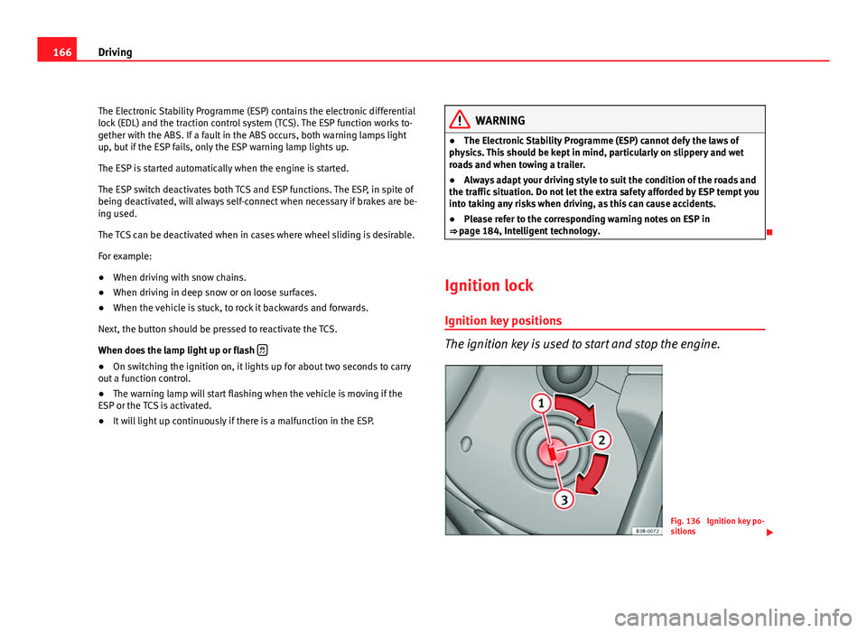
The ignition key is used to start and stop the engine.
Fig. 136 Ignition key po-
sitions