technical specifications Seat Exeo 2013 Owner's manual
[x] Cancel search | Manufacturer: SEAT, Model Year: 2013, Model line: Exeo, Model: Seat Exeo 2013Pages: 319, PDF Size: 4.81 MB
Page 281 of 319
279
If and when
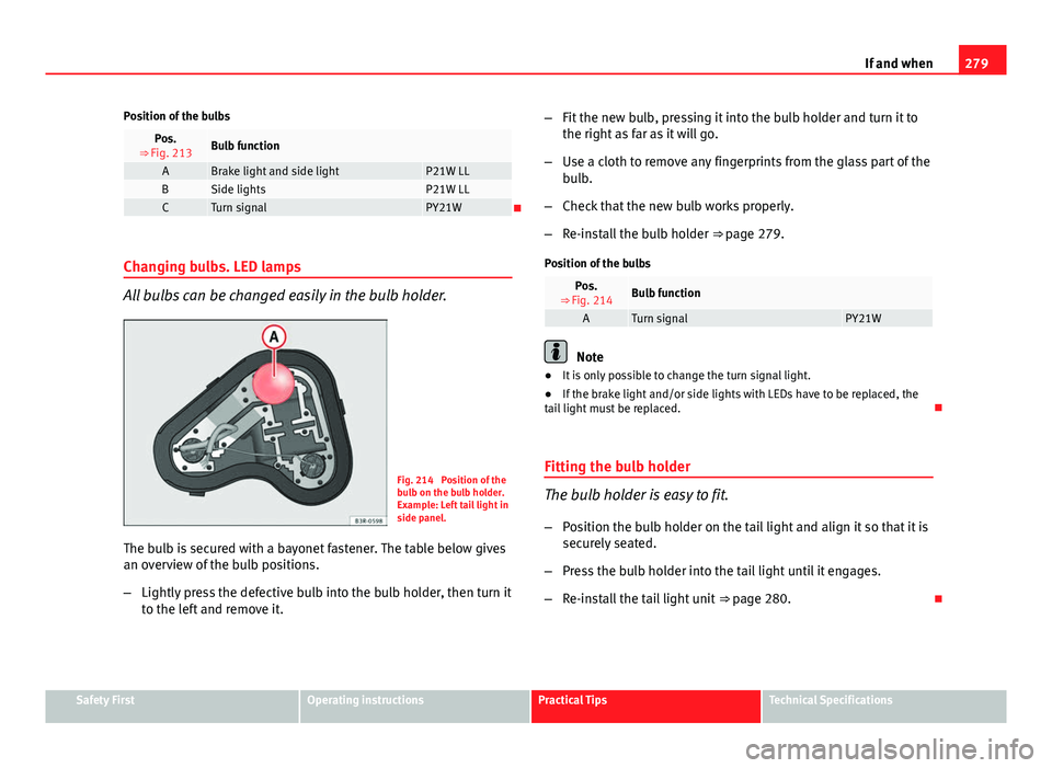
Position of the bulbs
Pos.
⇒ Fig. 213Bulb function
ABrake light and side lightP21W LLBSide lightsP21W LLCTurn signalPY21W
Changing bulbs. LED lamps
All bulbs can be changed easily in the bulb holder.
Fig. 214 Position of the
bulb on the bulb holder.
Example: Left tail light in
side panel.
The bulb is secured with a bayonet fastener. The table below gives
an overview of the bulb positions.
– Lightly press the defective bulb into the bulb holder, then turn it
to the left and remove it. –
Fit the new bulb, pressing it into the bulb holder and turn it to
the right as far as it will go.
– Use a cloth to remove any fingerprints from the glass part of the
bulb.
– Check that the new bulb works properly.
– Re-install the bulb holder ⇒ page 279.
Position of the bulbs
Pos.
⇒ Fig. 214Bulb function
ATurn signalPY21W
Note
● It is only possible to change the turn signal light.
● If the brake light and/or side lights with LEDs have to be replaced, the
tail light must be replaced.
Fitting the bulb holder
The bulb holder is easy to fit. – Position the bulb holder on the tail light and align it so that it is
securely seated.
– Press the bulb holder into the tail light until it engages.
– Re-install the tail light unit ⇒ page 280.
Safety FirstOperating instructionsPractical TipsTechnical Specifications
Page 283 of 319
281
If and when
Changing tail light bulbs (on rear lid)
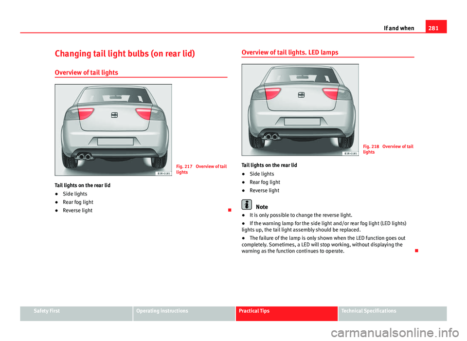
Overview of tail lights
Fig. 217 Overview of tail
lights
Tail lights on the rear lid
● Side lights
● Rear fog light
● Reverse light Overview of tail lights. LED lamps
Fig. 218 Overview of tail
lights
Tail lights on the rear lid
● Side lights
● Rear fog light
● Reverse light
Note
● It is only possible to change the reverse light.
● If the warning lamp for the side light and/or rear fog light (LED lights)
lights up, the tail light assembly should be replaced.
● The failure of the lamp is only shown when the LED function goes out
completely. Sometimes, a LED will stop working, without displaying the
warning as the function continues to operate.
Safety FirstOperating instructionsPractical TipsTechnical Specifications
Page 285 of 319
283
If and when
The bulbs are secured with a bayonet fastener. The table below
gives an overview of the bulb positions.
– Lightly press the defective bulb into the bulb holder, then turn it
to the left and remove it.
– Fit the new bulb, pressing it into the bulb holder and turn it to
the right as far as it will go.
– Use a cloth to remove any fingerprints from the glass part of the
bulb.
– Check that the new bulb works properly.
– Re-install the bulb holder ⇒ page 284.
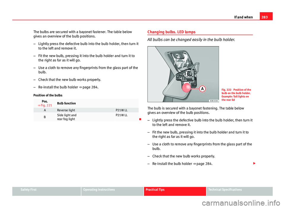
Position of the bulbs
Pos.
⇒ Fig. 221Bulb function
AReverse lightP21W LL
BSide light and
rear fog lightP21W LL Changing bulbs. LED lamps
All bulbs can be changed easily in the bulb holder.
Fig. 222 Position of the
bulb on the bulb holder.
Example: Tail lights on
the rear lid
The bulb is secured with a bayonet fastening. The table below
gives an overview of the bulb positions.
– Lightly press the defective bulb into the bulb holder, then turn it
to the left and remove it.
– Fit the new bulb, pressing it into the bulb holder and turn it to
the right as far as it will go.
– Use a cloth to remove any fingerprints from the glass part of the
bulb.
– Check that the new bulb works properly.
– Re-install the bulb holder ⇒ page 284.
Safety FirstOperating instructionsPractical TipsTechnical Specifications
Page 287 of 319
285
If and when
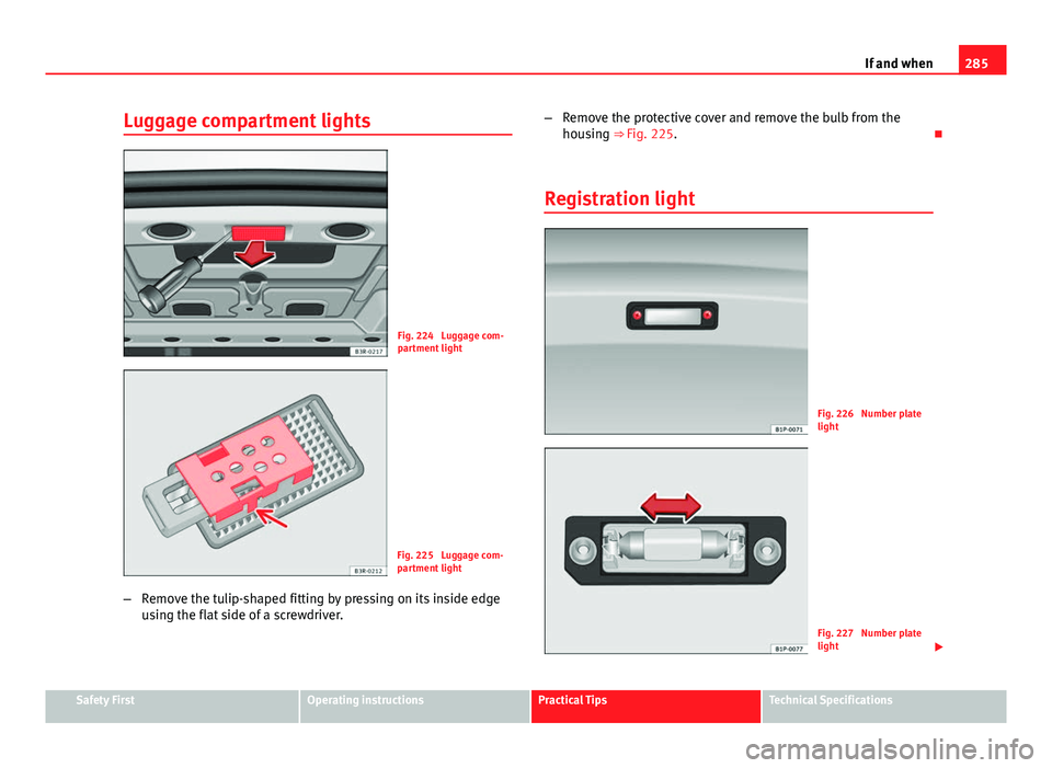
Luggage compartment lights
Fig. 224 Luggage com-
partment light
Fig. 225 Luggage com-
partment light
– Remove the tulip-shaped fitting by pressing on its inside edge
using the flat side of a screwdriver. –
Remove the protective cover and remove the bulb from the
housing ⇒ Fig. 225.
Registration light
Fig. 226 Number plate
light
Fig. 227 Number plate
light
Safety FirstOperating instructionsPractical TipsTechnical Specifications
Page 289 of 319

287
If and when
Jump leads
Jump leads must comply with standard DIN 72553 (see cable manufactur-
er's instructions). The wire cross section must be at least 25 mm 2
for petrol
engines and at least 35 mm 2
for diesel engines.
Note
● The vehicles must not touch each other, otherwise electricity could flow
as soon as the positive terminals are connected.
● The discharged battery must be properly connected to the on-board net-
work.
How to jump start: description
Fig. 230 Diagram of con-
nections for vehicles
without Start Stop sys-
tem
Fig. 231 Diagram of con-
nections for vehicles
with Start Stop system
Jump lead terminal connections
1. Switch off the ignition of both vehicles ⇒
.
2. For vehicles without Start-Stop system :
– Connect one end of the red jump lead to the positive +
termi-
nal of the vehicle with the flat battery A ⇒ Fig. 230.
– Connect the other end of the red jump lead to the positive ter-
minal +
in the vehicle providing assistance B.
– Connect one end of the black jump lead to the negative terminal
–
of the vehicle providing assistance B ⇒ Fig. 230.
– Connect the other end of the black jump lead X
to a solid met-
al component bolted to the engine block or to the engine block
itself of the vehicle with the flat battery. However, connect it to
a point as far as possible from the battery A
.
3. For vehicles with Start-Stop system :
Safety FirstOperating instructionsPractical TipsTechnical Specifications
Page 291 of 319
289
If and when
Note
The vehicles must not touch each other, otherwise electricity could flow as
soon as the positive terminals are connected.
Safety FirstOperating instructionsPractical TipsTechnical Specifications
Page 293 of 319
291
If and when
Do not pull too hard with the towing vehicle and take care to avoid jerking
the tow rope. When towing on an unpaved road, there is always a risk of
overloading and damaging the anchorage points.
The ignition of the vehicle being towed must be switched on to prevent the
steering wheel from locking and also to allow the use of the turn signals,
horn, windscreen wipers and washers.
As the brake servo does not work if the engine is not running, you must ap-
ply considerably more pressure to the brake pedal than you normally would.
As the power assisted steering does not work if the engine is not running,
you will need more strength to steer than you normally would.
Towing vehicles with an automatic gearbox
● Put the selector lever into position “N”.
● Do not drive faster than 50 km/h (30 mph).
● Do not tow further than 50 km.
● If a breakdown vehicle is used, the vehicle must be towed with the front
wheels raised.
Note
● Observe legal requirements when towing or tow-starting.
● Switch on the hazard warning lights of both vehicles. However, observe
any regulations to the contrary.
● For technical reasons, vehicles with an automatic gearbox must not be
tow-started.
● If damage to your vehicle means that there is no lubricant in the gear-
box, you must raise the driven wheels while the vehicle is being towed.
● If the vehicle has to be towed more than 50 km (30 miles), the front
wheels should be raised during towing, and towing should be carried out by
a qualified person. ●
The steering wheel is locked when the vehicle has no electrical power.
The vehicle must then be towed with the front wheels raised. Towing should
be carried out by a qualified person.
● The towline anchorage should always be kept in the vehicle. Please refer
to the notes ⇒ page 290, Tow-starting.
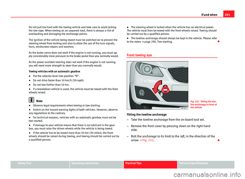
Front towing eyeFig. 232 Fitting the tow-
line anchorage to front of
the vehicle
Fitting the towline anchorage
– Take the towline anchorage from the on-board tool set.
– Remove the front cover by pressing down on the right hand
side.
– Bolt the anchorage to its limit to the left, in the direction of the
arrow ⇒ Fig. 232.
Safety FirstOperating instructionsPractical TipsTechnical Specifications
Page 295 of 319

293
Description of specifications
Technical Specifications
Description of specifications Important information
Important
The information in the vehicle documentation always takes
precedence over the information in this Instruction Manual.
All technical specifications provided in this documentation are valid for the
standard model in Spain. The vehicle data card included in the Mainte-
nance Programme or the vehicle registration documentation shows which
engine is installed in the vehicle.
The figures may be different depending whether additional equipment is fit-
ted, for different models, for special vehicles and for other countries. Abbreviations used in the Technical Specifications section
Abbrevia-
tionMeaning
kWKilowatt, engine power measurement.
PSPferdestärke (horsepower), formerly used to denote engine
power.
rpmRevolutions per minute - engine speed.NmNewton metres, unit of engine torque.litres per100 kmFuel consumption in litres per 100 km (70 miles).
g/kmCarbon dioxide emissions in grams per km (mile) travelled.CO 2Carbon dioxideCNCetane number, indication of the diesel combustion power.
RONResearch octane number, indication of the knock resistance
of petrol.
Safety FirstOperating instructionsPractical TipsTechnical Specifications
Page 297 of 319
295
Description of specifications
The fuel consumption and CO 2 emissions do not depend only on the per-
formance of the vehicle, they can also differ from the established values de-
pending on other factors such as driving style, road conditions, traffic con-
ditions, environmental conditions, load and number of passengers.
Calculation of fuel consumption
The consumption values have been calculated based on measurements per-
formed or supervised by certified CE laboratories according to the latest ver-
sion of directives 715/2007/EC and 80/1268/CEE (for more information
consult the European Union Publications Office at EUR-Lex: © European Un-
ion, http://eur-lex.europa.eu/en/index.htm) and are valid for the kerb
weight indicated for the vehicle.
Note
In practice, and considering all the factors mentioned here, consumption
values can differ from those calculated in the current European regulations.
Weights
Kerb weight refers to the basic model with a fuel tank filled to 90% capacity
and without optional extras. The figure quoted includes 75 kg to allow for
the weight of the driver.
For special versions and optional equipment fittings or for the addition of
accessories, the weight of the vehicle will increase ⇒
.
WARNING
● Please note that the centre of gravity may shift when transporting
heavy objects; this may affect vehicle handling and lead to an accident.
Always adjust your speed and driving style to suit road conditions and re-
quirements.
● Never exceed the gross axle weight rating or the gross vehicle weight
rating. If the allowed axle load or the allowed total weight is exceeded,
the driving characteristics of the vehicle may change, leading to acci-
dents, injuries and damage to the vehicle.
Safety FirstOperating instructionsPractical TipsTechnical Specifications
Page 298 of 319

296Description of specifications
Towing a trailer
Trailer weights
Trailer weight
The trailer weights and drawbar loads approved are selected in intensive tri-
als according to precisely defined criteria. The approved trailer weights are
valid for vehicles in the EU for maximum speeds of 80 km/h (50 mph) (in
certain circumstances up to 100 km/h (60 mph). The figures may be differ-
ent in other countries. All data in the official vehicle documentation takes
precedence over these data at all times ⇒
.
Drawbar loads
The maximum permitted drawbar load on the ball joint of the towing bracket
must not exceed 75 kg.
In the interest of road safety, we recommend that you always tow approach-
ing the maximum drawbar load. The response of the trailer on the road will
be poor if the drawbar load is too small.
If the maximum permissible drawbar load cannot be met (e.g. with small,
empty and light-weight single axle trailers or tandem axle trailers with a
wheelbase of less than 1 metre), a minimum of 4% of the actual trailer
weight is legally required for the drawbar load.
WARNING
● For safety reasons, do not exceed the 80 km/h (50 mph) limit. This is
also valid in countries where higher speeds are permitted.
● Never exceed the maximum trailer weights or the drawbar load. If the
permissible axle load or the permissible total weight is exceeded, the
driving characteristics of the vehicle may change, leading to accidents,
injuries and damage to the vehicle.
Wheels
Tyre pressure, snow chains, wheel bolts
Tyre pressures
The sticker with the tyre pressure values can be found on the inside of the
fuel tank flap. The tyre pressure values given there are for cold tyres. The
slightly raised pressures of warm tyres must not be reduced. ⇒
Snow chains
Snow chains may be fitted only to the front wheels.
Consult the section “wheels” of this manual.
Wheel bolts
After the wheels have been changed, the tightening torque of the wheel
bolts should be checked as soon as possible with a torque wrench ⇒
.
The tightening torque for steel and alloy wheels is 120 Nm.
WARNING
● Check the tyre pressure at least once per month. Checking the tyre
pressure is very important. If the tyre pressure is too high or too low,
there is an increased danger of accidents, particularly at high speeds.
● If the tightening torque of the wheel bolts is too low, they could loos-
en while the vehicle is in motion. Risk of accident! If the tightening tor-
que is too high, the wheel bolts and threads can be damaged.
Note
We recommend that you ask your Technical Service for information about
appropriate wheel, tyre and snow chain size.