ESP Seat Exeo 2013 Owner's Guide
[x] Cancel search | Manufacturer: SEAT, Model Year: 2013, Model line: Exeo, Model: Seat Exeo 2013Pages: 319, PDF Size: 4.81 MB
Page 115 of 319
113
Opening and closing
– With the control in position 0, press the control briefly to make
the roof tilt open all the way.
– To open the roof as far as an intermediate setting, press and
hold the control until the roof has moved to the desired posi-
tion.
When you release the switch it will automatically spring back from position 2
to position 1.
The sliding sun blind in the headliner automatically opens when the sunroof
is slid open. If required, it can be closed by hand when the sunroof is
closed.
It is advisable to close the sun blind when the vehicle is left standing in the
sun. It is important to remember to close the sunroof when parking the vehi-
cle or if it suddenly starts raining, especially when the sun blind is closed.
For further information on the automatic close function, see ⇒ page 113.
Closing
Closing
– Turn the control to position 0
⇒ Fig. 82 to close the sunroof
⇒ .
Closing the sunroof from the tilt position
– Pull the specially formed rear end of the control and hold it until
the sunroof has moved down to the desired position.
– Pull the switch briefly to lower the sunroof automatically to the
fully closed position. If required, the sunroof can be stopped in
any position by briefly pulling the control again ⇒
.
WARNING
Take care when closing the sunroof. There is a risk of suffering injury. For
this reason, always take out the ignition key when leaving the vehicle.
Automatic close function
The sunroof can also be closed from outside the vehicle.
– Turn the key in the lock on the driver door and hold it in the lock
position or press the lock button on the remote control until the
sunroof has closed all the way ⇒
.
WARNING
Take care when closing the sunroof. There is a risk of suffering injury.
Solar sunroof*
The solar cells in the sunroof power the air conditioner fan.
The solar sunroof is operated in the same way as the normal sliding/tilting
sunroof.
The interior trim is fixed to the solar sunroof and cannot be opened and
closed separately.
Safety FirstOperating instructionsPractical TipsTechnical Specifications
Page 118 of 319
116Lights and visibility
Automatic headlight switch* (sensor-controlled)
If you set the light switch to “AUTO”, the dipped headlights
will switch on and off automatically according to the ambi-
ent light level.
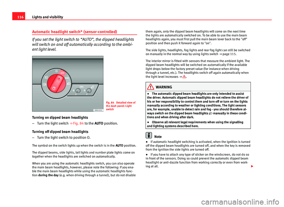
Fig. 84 Detailed view of
the dash panel: Light
switch
Turning on dipped beam headlights
– Turn the light switch ⇒ Fig. 84 to the AUTO position.
Turning off dipped beam headlights
– Turn the light switch to position O.
The symbol on the switch lights up when the switch is in the AUTO position.
The dipped beams, side lights, tail lights and number plate lights come on
together when the headlights are switched on automatically.
When you are using the automatic headlights switch, you can also operate
the main beam headlights, however, please note the following: If you ena-
ble the main beam headlights while using the automatic headlights func-
tion during the day (e.g. when driving through a tunnel), but do not disable them again, only the dipped beam headlights will come on the next time
the lights are automatically switched on. To be able to use the main beam
headlights again, you must first pull the main beam lever back to the "off"
position and then push it forward again to "on".
The side lights, headlights, fog lights and rear fog light can still be switched
on manually in the normal way by using lights switch
⇒ page 115.
The interior mirror is fitted with sensors that measure the ambient light. The
dipped beam headlights will be switched on automatically if the available
light drops below the factory preset value (for instance when driving
through a tunnel, etc.). The headlights switch off again automatically when
the light level increases ⇒
.
WARNING
● The automatic dipped beam headlights are only intended to assist
the driver. Automatic dipped beam headlights do not relieve the driver of
his or her responsibility to control them and turn off or turn on the lights
manually according to weather or lighting conditions. The light sensors
are, for example, unable to detect rain and fog - you should therefore al-
ways switch on the dipped beam headlights manually in these condi-
tions and when driving after dark.
● Observe all relevant legal requirements when using the signalling
and lighting systems described here.
Note
● If automatic headlight switching is activated, when the ignition is turned
off the dipped beam headlights are turned off, and when the key is removed
from the ignition the side lights are turned off.
● If you have to attach any type of sticker on the windscreen, do not do so
in front of the sensors. Doing so could prevent the automatic dipped beam
headlight or anti-dazzle function from working correctly or even from work-
ing at all.
Page 120 of 319
118Lights and visibility
Activating the function
–Briefly press the knob ⇒ Fig. 85 to release it from its set posi-
tion.
– Turn the knob to position 1.
– Press the knob in again to prevent the setting from being
changed unintentionally.
Deactivating the function
– Briefly press the knob ⇒ Fig. 85 to release it from its set posi-
tion.
– Turn the knob to position 0.
– Press the knob in again to prevent the setting from being
changed unintentionally.
The coming home and leaving home functions are controlled by light sen-
sors in the interior mirror housing. The system will function when the follow-
ing requirements are met:
● The knob is set to position 1.
● The headlights and the ignition are switched off.
● Dark conditions; the sensors register little or no light.
Coming home
When the system is enabled and it is dark, the corresponding exterior lights
switch on as soon as the driver door is opened.
The exterior lights will stay on for up to a maximum of 2 minutes as long as
one of the doors or the rear lid is open.
The exterior lights stay on for about 30 seconds to light up the area around
the vehicle after all the doors and the rear lid have been closed. This time interval is factory-set, but you can have it changed by a special-
ised workshop to suit your own requirements (max. setting is 60 seconds).
Leaving home
The exterior lights are switched on when the vehicle is unlocked with the
button on the remote control key.
The exterior lights go out when the driver door is opened or after 60 sec-
onds when the vehicle locks itself again automatically
⇒ page 106.
WARNING
Before leaving the vehicle, remove the key from the ignition, as the lights
will not go out if the coming home function is activated. This will lead to
battery discharge and vehicle breakdown.
Note
● If you always wish to use the coming home and leaving home functions,
you can leave them permanently switched on. As the system is controlled
via a photosensor, it will only work in dark conditions.
● Permanent use of the coming home and leaving home functions, partic-
ularly on short journeys, will increase the load on the battery. To make sure
the battery is always sufficiently charged, occasionally drive longer distan-
ces.
● If the fog lights have been switched on by the coming home and leaving
home functions, they will always be switched off when you switch on the ig-
nition.
● Observe all relevant legal requirements when using the signalling and
lighting systems described here.
Page 121 of 319
119
Lights and visibility
Instrument lighting
The brightness of the instrument lighting, displays and cen-
tre console lighting can be varied as required.
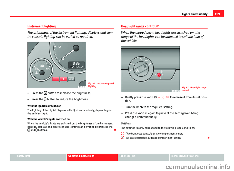
Fig. 86 Instrument panel
lighting
– Press the +
button to increase the brightness.
– Press the -
button to reduce the brightness.
With the ignition switched on
The lighting of the digital displays will adjust automatically, depending on
the ambient light.
With the vehicle's lights switched on
When the vehicle's lights are switched on, the brightness of the instrument
lighting, displays and centre console lighting can be varied by pressing the +
and - buttons. Headlight range control
When the dipped beam headlights are switched on, the
range of the headlights can be adjusted to suit the load of
the vehicle.
Fig. 87 Headlight range
control
– Briefly press the knob ⇒ Fig. 87 to release it from its set posi-
tion.
– Turn the knob to the required setting.
– Press the knob in again to prevent the setting from being
changed unintentionally.
Settings
The settings roughly correspond to the following load conditions: Two front occupants, luggage compartment empty
All seats occupied, luggage compartment empty
O
1
Safety FirstOperating instructionsPractical TipsTechnical Specifications
Page 125 of 319
123
Lights and visibility
Main beam headlights
– Press the lever forward to switch on the main beams.
– Pull the lever back towards you to switch the main beam head-
lights off again.
Headlight flasher
– Pull the lever towards the steering wheel to operate the flasher.
Parking light
– Switch the ignition off.
– Move the lever up or down to turn on the right or left-hand park-
ing lights respectively.
Notes on these functions
● The turn signals only work when the ignition is switched on. The turn
signal lamp or flashes in the instrument panel when the turns signals
⇒ page 65 are working.
● The turn signals are cancelled automatically when the steering wheel is
returned to the straight-ahead position.
● The main beam headlights can only be switched on if the dipped beam
headlights are already on. The main beam headlight indicator lamp then
comes on in the instrument panel.
● The headlight flasher comes on for as long as you pull the lever, even if
no other lights are switched on. The main beam headlight indicator lamp
then comes on in the instrument panel.
● When the parking lights are switched on, the headlight and the tail light
on one side of the vehicle light up with reduced intensity. The parking lights
will only work with the ignition off.
CAUTION
Never use the main beam headlights or the headlight flasher if this would
dazzle oncoming traffic.
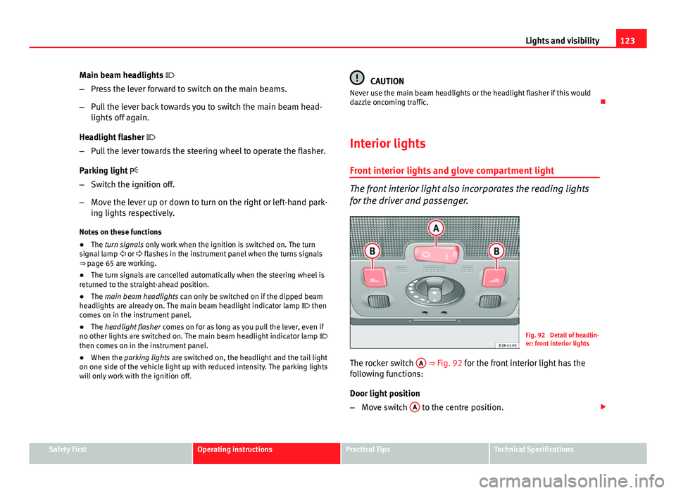
Interior lights
Front interior lights and glove compartment light
The front interior light also incorporates the reading lights
for the driver and passenger.
Fig. 92 Detail of headlin-
er: front interior lights
The rocker switch A
⇒
Fig. 92 for the front interior light has the
following functions:
Door light position
– Move switch A
to the centre position.
Safety FirstOperating instructionsPractical TipsTechnical Specifications
Page 133 of 319
131
Lights and visibility
Switching off the anti-dazzle function
– Press button A
⇒ Fig. 102. Control lamp B goes off.
Switching on the anti-dazzle function
– Press button A
⇒ Fig. 102. Indicator lamp B turns on.
Anti-dazzle function
The anti-dazzle function is activated every time the ignition is switched on.
The green warning lamp lights up in the rear vision mirror housing.
When the anti-dazzle function is enabled, the interior rear vision mirror will
darken automatically according to the amount of light it receives. The anti-
dazzle function is disabled if:
● the interior lighting is switched on
● reverse gear is engaged
Sensors for automatic headlights*
When the light switch is set to the AUTO position, the dipped beam head-
lights are switched on and off automatically according to the ambient light
level with the aid of the sensors located in the interior mirror ⇒ page 116.
WARNING
Electrolyte fluid can leak from a broken mirror. This could cause irritation
to the skin, eyes and respiratory organs. If you come into contact with
this liquid, it must be rinsed with large quantities of water. Seek medical
assistance if needed!
CAUTION
Electrolyte fluid leaking from a broken mirror can cause damage to plastic
surfaces. Use a sponge or similar to remove the fluid as soon as possible.
Note
● The interior mirror automatic anti-dazzle function* will only work proper-
ly if the sun blind* for the rear window is retracted and if there are no other
objects preventing light from reaching the mirror.
● If you have to stick any type of sticker on the windscreen, do not do so in
front of the sensors. Doing so could prevent the automatic headlight or anti-
dazzle function from working correctly or even from working at all.
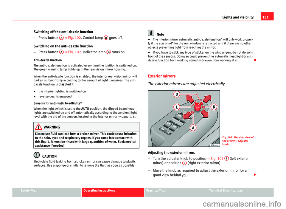
Exterior mirrors
The exterior mirrors are adjusted electrically.
Fig. 103 Detailed view of
the armrest: Adjuster
knob
Adjusting the exterior mirrors
– Turn the adjuster knob to position ⇒
Fig. 103 L
(left exterior
mirror) or position R (right exterior mirror).
– Move the knob as required to adjust the exterior mirror for a
good view behind you.
Safety FirstOperating instructionsPractical TipsTechnical Specifications
Page 137 of 319
135
Seats and storage
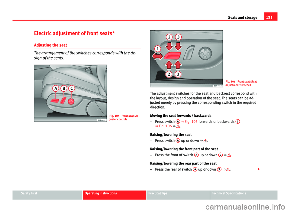
Electric adjustment of front seats*
Adjusting the seat
The arrangement of the switches corresponds with the de-
sign of the seats.
Fig. 105 Front seat: Ad-
juster controls
Fig. 106 Front seat: Seat
adjustment switches
The adjustment switches for the seat and backrest correspond with
the layout, design and operation of the seat. The seats can be ad-
justed merely by pressing the corresponding switch in the required
direction.
Moving the seat forwards / backwards
– Press switch A
⇒ Fig. 105 forwards or backwards 1⇒ Fig. 106 ⇒ .
Raising/lowering the seat
– Press switch A
up or down ⇒ .
Raising/lowering the front part of the seat
– Press the front of switch A
up or down 2 ⇒ .
Raising/lowering the rear part of the seat
– Press the rear of switch A
up or down 3 ⇒ .
Safety FirstOperating instructionsPractical TipsTechnical Specifications
Page 139 of 319
137
Seats and storage
– Press the rear part of the adjuster switch to decrease the con-
tour of the lumbar support.
Adjusting the height
– Press the top part of the adjuster switch to move the contour
upwards.
– Press the bottom part of the adjuster switch to move the con-
tour down.
The lumbar support provides effective support for the natural curvature of
the spine to give a more relaxed seating position, especially on long jour-
neys. Driver seat memory*
Description
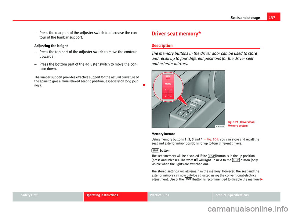
The memory buttons in the driver door can be used to store
and recall up to four different positions for the driver seat
and exterior mirrors.
Fig. 109 Driver door:
Memory system
Memory buttons
Using memory buttons 1, 2, 3 and 4 ⇒ Fig. 109, you can store and recall the
seat and exterior mirror positions for up to four different drivers.
STOP
button
The seat memory will be disabled if the STOP button is in the up position
(press and release). The word will light up next to the STOP button (only
visible when the lights are switched on).
The stored settings will all remain in the memory. However, the seat and the
exterior mirrors can now only be adjusted using the conventional electrical
adjustment. Use of the STOP
button is recommended to disable the memory
Safety FirstOperating instructionsPractical TipsTechnical Specifications
Page 147 of 319
145
Seats and storage
Note
Do not fold away the ski bag after use if it is still damp.
Roof rack
Description
Additional luggage can be carried on the roof rack. Note the following points if you intend to carry loads on the roof:
● There are aerodynamic drainage channels on the roof of the vehicle and,
therefore, normal roof racks cannot be used. We recommend using the ba-
sic support units from the range of genuine SEAT accessories.
● These basic supports are the base of a complete roof rack system. For
safety reasons, however, the corresponding additional fastenings must be
fitted to carry luggage, bicycles, surfboards, skis and boats. All the parts of
this system are available from SEAT Official Services.
CAUTION
Any damage to the vehicle caused by the use of other types of roof rack or
incorrect installation will not be covered by the factory warranty. The roof
rack system must therefore be installed exactly according to the instructions
provided. Attachment points
The roof rack must be attached at the marked points only.
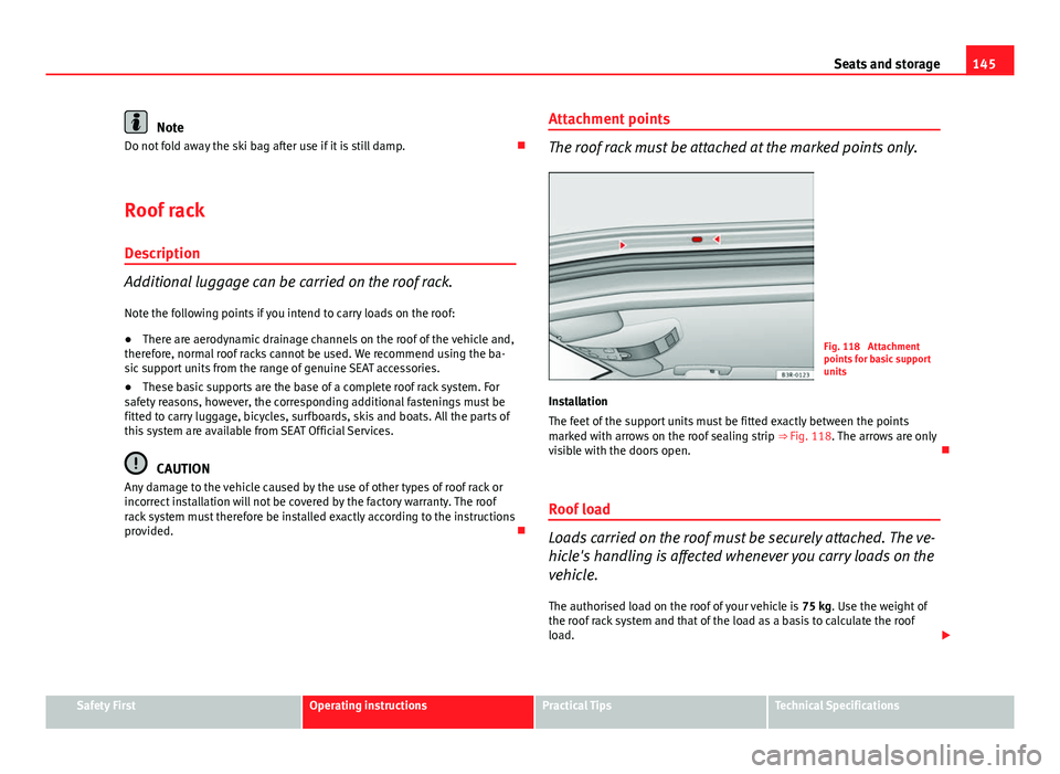
Fig. 118 Attachment
points for basic support
units
Installation
The feet of the support units must be fitted exactly between the points
marked with arrows on the roof sealing strip ⇒ Fig. 118. The arrows are only
visible with the doors open.
Roof load
Loads carried on the roof must be securely attached. The ve-
hicle's handling is affected whenever you carry loads on the
vehicle. The authorised load on the roof of your vehicle is 75 kg. Use the weight of
the roof rack system and that of the load as a basis to calculate the roof
load.
Safety FirstOperating instructionsPractical TipsTechnical Specifications
Page 168 of 319
166Driving
The Electronic Stability Control (ESC) contains the electronic differential lock
(EDL) and the traction control system (ASR). The ESC works together with
the ABS. If a fault in the ABS occurs, both warning lamps light up, but if the
ESC fails, only the ESC warning lamp lights up.
The ESC system is started automatically when the engine is started.
The ESC system is always active and cannot be switched off. The ESC switch
only switches the ASR off.
The ASR can be deactivated when wheel spin is desirable.
For example:
● When driving with snow chains.
● When driving in deep snow or on loose surfaces.
● When the vehicle is stuck, to rock it backwards and forwards.
Press the button to switch the ASR back on when you no longer need wheel
spin.
Situations in which the warning lamp lights
●
On switching the ignition on, it lights up for about two seconds to carry
out a function control.
● The warning lamp will start flashing when the vehicle is moving if the
ESC or the ASR is activated.
● It will light up continuously if there is a fault in the ESC.
WARNING
● Do not forget that the Electronic stability control ESC cannot defy the
laws of physics. This should be kept in mind, particularly on slippery and
wet roads and when towing a trailer.
● Always adapt your driving style to suit the condition of the roads and
the traffic situation. The greater safety provided by the ESC should not
encourage you to run any risks.
● Please refer to the corresponding warning notes on ESC in
⇒ page 188, Intelligent technology.
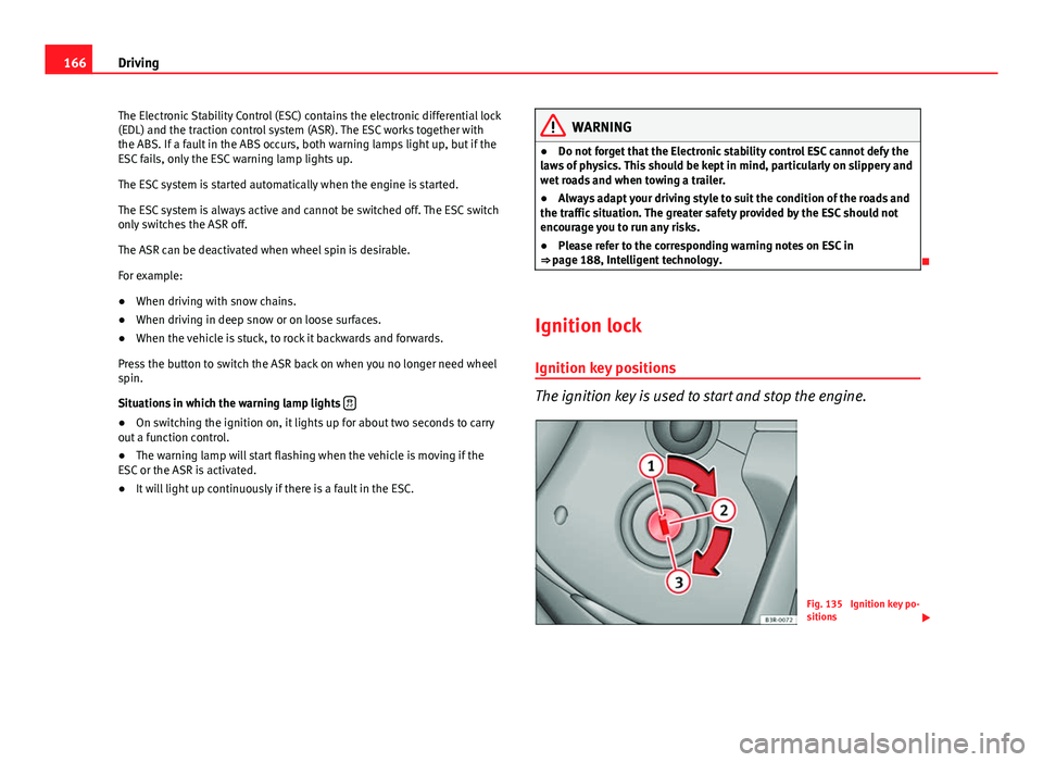
Ignition lock Ignition key positions
The ignition key is used to start and stop the engine.
Fig. 135 Ignition key po-
sitions