lock Seat Exeo ST 2010 Manual Online
[x] Cancel search | Manufacturer: SEAT, Model Year: 2010, Model line: Exeo ST, Model: Seat Exeo ST 2010Pages: 325, PDF Size: 9.34 MB
Page 274 of 325

If and when
272Changing the dipped beam headlight bulb
The procedure for changing the bulb is the same on both
sides.
– Switch off the ignition and the lights.
– Raise the bonnet.
– Move the brace ⇒ fig. 208 in the direction of the arrow and
remove the rigid cover, separating the brace side and then
removing the two tabs from the other end of the cover.
– Pull the connector ⇒ fig. 209 from the bulb.
– Unclip the retainer spring ⇒fig. 209 pressing inwards to the
right.
– Remove the bulb and fit the new one in the headlight casing with the tab upwards, starting to position it from below.
– Clip on the spring, raising it and pressing it slightly while turning
it anti-clockwise. To ensure correct lighting, the filament must be
vertical. When changing the bulb, you can check the position of
the bulb through the headlight glass.
– Connect the connector to the bulb.
– Fit the cover, first inserting the side tabs and then closing the cover and the brace. Make sure that the gasket sits well on the
casing cover during the operation.
– Check whether the new bulb is working.
– Have the headlight settings checked as soon as possible.
Fig. 208 Dipped beam
headlightsFig. 209 Dipped beam
headlights
A1A2
A3
ExeoST_EN.book Seite 272 Freitag, 3. September 2010 11:41 11
Page 275 of 325
If and when273
Safety First
Operating Instructions
Practical Tips
Technical Specifications
Changing the side light bulb (outside of vehicle)
The procedure for changing the bulb is the same on both
sides.
– Switch off the ignition and the lights.
– Raise the bonnet.
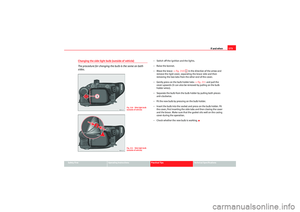
– Move the brace ⇒fig. 210 in the direction of the arrow and
remove the rigid cover, separating the brace side and then
removing the two tabs from the other end of the cover.
– Gently press on the bulb holder tabs ⇒fig. 211 and pull the
cover upwards (it can also be removed by pulling on the bulb
holder wires).
– Separate the bulb from the bulb holder by pulling both pieces anti-clockwise.
– Fit the new bulb by pressing on the bulb holder.
– Insert the bulb into the socket and press on the bulb holder. Fit the cover, first inserting the side tabs and then closing the cover
and the brace. Make sure that the gasket sits well on the casing
cover during the operation.
– Check whether the new bulb is working.
Fig. 210 Side light bulb
(outside of vehicle)Fig. 211 Side light bulb
(outside of vehicle)
A1
ExeoST_EN.book Seite 273 Freitag, 3. September 2010 11:41 11
Page 276 of 325
If and when
274Changing the side light bulb (inside of vehicle)
The procedure for changing the bulb is the same on both
sides.
– Switch off the ignition and the lights.
– Raise the bonnet.
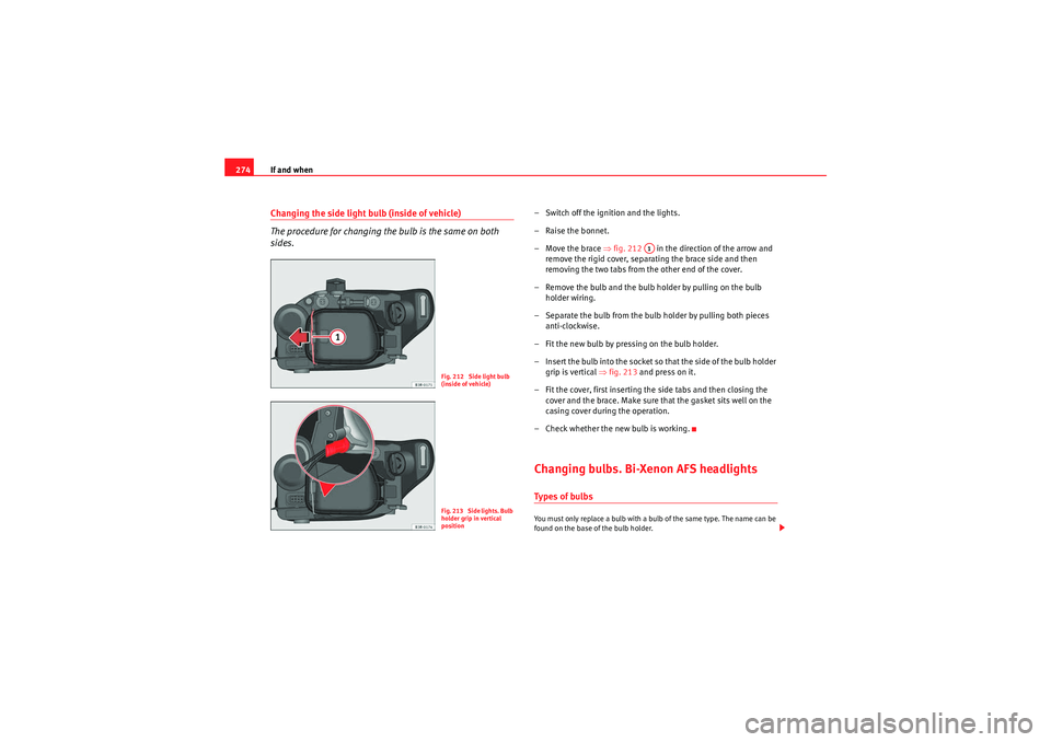
– Move the brace ⇒ fig. 212 in the direction of the arrow and
remove the rigid cover, separating the brace side and then
removing the two tabs from the other end of the cover.
– Remove the bulb and the bulb holder by pulling on the bulb holder wiring.
– Separate the bulb from the bulb holder by pulling both pieces anti-clockwise.
– Fit the new bulb by pressing on the bulb holder.
– Insert the bulb into the socket so that the side of the bulb holder grip is vertical ⇒fig. 213 and press on it.
– Fit the cover, first inserting the side tabs and then closing the cover and the brace. Make sure that the gasket sits well on the
casing cover during the operation.
– Check whether the new bulb is working.Changing bulbs. Bi-Xenon AFS headlightsTypes of bulbsYou must only replace a bulb with a bulb of the same type. The name can be
found on the base of the bulb holder.
Fig. 212 Side light bulb
(inside of vehicle)Fig. 213 Side lights. Bulb
holder grip in vertical
position
A1
ExeoST_EN.book Seite 274 Freitag, 3. September 2010 11:41 11
Page 279 of 325
If and when277
Safety First
Operating Instructions
Practical Tips
Technical Specifications
Changing the DRL light bulb (daytime running light)
The procedure for changing the bulb is the same on both
sides.– Switch off the ignition and the lights.
– Raise the bonnet.
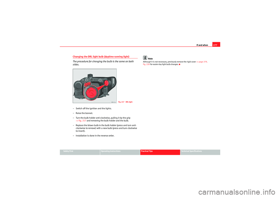
– Turn the bulb holder anti-clockwise, pulling it by the grip
⇒fig. 217 and removing the bulb holder and the bulb.
– Replace the blown bulb in the bulb holder (press and turn anti- clockwise to remove) with a new bulb (press and turn clockwise
to insert).
– Installation is done in the reverse order. Note
Although it is not necessary, previously remove the rigid cover
⇒page 279,
fig. 220 for easier day light bulb changes.
Fig. 217 DRL light
ExeoST_EN.book Seite 277 Freitag, 3. September 2010 11:41 11
Page 280 of 325
If and when
278Changing the turn signal bulb
The procedure for changing the bulb is the same on both
sides.
– Switch off the ignition and the lights.
– Raise the bonnet.
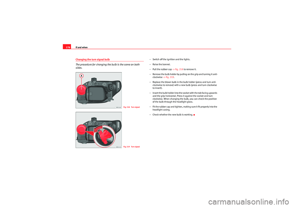
– Pull the rubber cap ⇒ fig. 218 to remove it.
– Remove the bulb holder by pulling on the grip and turning it anti- clockwise ⇒fig. 219 .
– Replace the blown bulb in the bulb holder (press and turn anti- clockwise to remove) with a new bulb (press and turn clockwise
to insert).
– Insert the bulb holder into the socket with the tab facing upwards and the grip horizontal. Press it against the socket and turn
clockwise. When changing the bulb, you can check the position
of the bulb through the headlight glass.
– Fit the rubber cap and tighten, making sure it fit properly into the headlight casing.
– Check whether the new bulb is working.
Fig. 218 Turn signalFig. 219 Turn signal
ExeoST_EN.book Seite 278 Freitag, 3. September 2010 11:41 11
Page 281 of 325
If and when279
Safety First
Operating Instructions
Practical Tips
Technical Specifications
Changing the side light bulb
The procedure for changing the bulb is the same on both
sides.
– Switch off the ignition and the lights.
– Raise the bonnet.
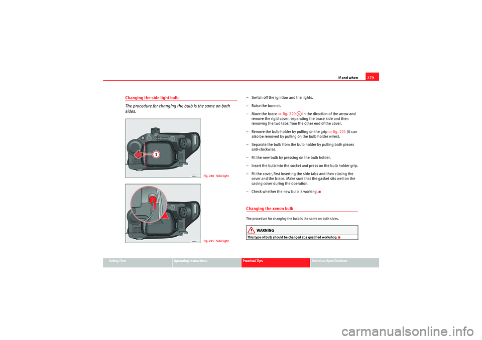
– Move the brace ⇒fig. 220 in the direction of the arrow and
remove the rigid cover, separating the brace side and then
removing the two tabs from the other end of the cover.
– Remove the bulb holder by pulling on the grip ⇒fig. 221 (it can
also be removed by pulling on the bulb holder wires).
– Separate the bulb from the bulb holder by pulling both pieces anti-clockwise.
– Fit the new bulb by pressing on the bulb holder.
– Insert the bulb into the socket and press on the bulb holder grip.
– Fit the cover, first inserting the side tabs and then closing the cover and the brace. Make sure that the gasket sits well on the
casing cover during the operation.
– Check whether the new bulb is working.Changing the xenon bulbThe procedure for changing the bulb is the same on both sides.
WARNING
This type of bulb should be changed at a qualified workshop.
Fig. 220 Side lightFig. 221 Side light
A1
ExeoST_EN.book Seite 279 Freitag, 3. September 2010 11:41 11
Page 283 of 325

If and when281
Safety First
Operating Instructions
Practical Tips
Technical Specifications
Removing the tail light
To change the bulbs you must remove the tail light assembly.
Removing the light requires a certain degree of practical skill.
A special retaining screw is used to secure and guide the tail light.
– Check which of the bulbs is defective.
–Open the tailgate.
– Take the screwdriver out of the vehicle's tool kit ⇒page 254.
– Use the flat-blade side of th e reversible screwdriver insert.
– Prise off the cover with a screwdriver in the slot ⇒fig. 224
and remove the cover (with the retaining clips) from the opening.
– Carefully loosen the screw located behind the cover with the screwdriver, turning it anti-clockwise (arrows) .
– Gradually ease the tail light out of the housing ( ⇒fig. 225 posi-
tions and ) by pulling alternately in positions and .
– Remove the bulb holder ⇒page 282.
CautionWhen removing or installing the tail light, take care not to cause any damage.•Removing the tail light in particular can lead to the paintwork or tail light
becoming damaged. This is another reason why we recommend having the
bulbs changed by a qualified workshop.Note
Make sure you have a soft cloth ready to place under the glass on the tail
light, to avoid any scratches.
Fig. 224 Luggage
compartment: Location of
the bolt securing the tail
light unitFig. 225 Removing tail
light from side panel
A1
A2
A3
A4
A1
A2
ExeoST_EN.book Seite 281 Freitag, 3. September 2010 11:41 11
Page 294 of 325
If and when
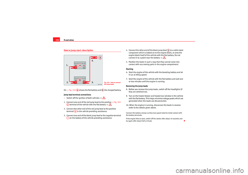
292How to jump start: descriptionOn ⇒fig. 245 shows the flat battery and the charged battery.
Jump lead terminal connections
– Switch off the ignition of both vehicles ⇒.
1. Connect one end of the red jump lead to the positive ⇒fig. 245
terminal of the vehicle with the flat battery ⇒.
2. Connect the other end of the red jump lead to the positive terminal in the vehicle providing assistance.
3. Connect one end of the black jump lead to the negative terminal on the battery of the vehicle providing assistance. 4. Connect the other end of the black jump lead to a solid metal
component which is bolted on to the engine block, or onto the
engine block itself of the vehicle with the flat battery. Do not
connect it to a point near the battery ⇒.
5. Position the leads in such a way that they cannot come into contact with any moving parts in the engine compartment.
Starting
6. Start the engine of the vehicle with the boosting battery and let it run at idling speed.
7. Start the engine of the vehicle with the flat battery and wait one or two minutes until the engine is running.
Removing the jump leads
8. Before you remove the jump lead s, switch off the headlights (if
they are switched on).
9. Turn on the heater blower and heated rear window in the vehicle with the flat battery. This helps minimise voltage peaks which are
generated when the leads are disconnected.
10. When the engine is running, disconnect the leads in reverse order to the details given above.
Connect the battery clamps so they have good metal-to-metal contact with
the battery terminals.
If the engine fails to start, switch off the starter after about 10 seconds and
try again after about half a minute.
Fig. 245 How to connect
the jump leads
AA
AB
A+
A+
A-
AX
ExeoST_EN.book Seite 292 Freitag, 3. September 2010 11:41 11
Page 297 of 325

If and when295
Safety First
Operating Instructions
Practical Tips
Technical Specifications
Do not pull too hard with the towing vehicle and take care to avoid jerking the
tow-rope. When towing on an unpaved road, there is always a risk of over-
loading and damaging the anchorage points.
The ignition of the vehicle being towed must be switched on to prevent the
steering wheel from locking and also to allow the use of the turn signals,
horn, windscreen wipers and washers.
As the brake servo does not work if the engine is not running, you must apply
considerably more pressure to the brake pedal than you normally would.
As the power assisted steering does not work if the engine is not running, you
will need more strength to steer than you normally would.
Towing vehicles with an automatic gearbox
•Put the selector lever into position “N”.•Do not drive faster than 50 km/h when towing a vehicle.•Do not tow further than 50 km.•If a breakdown vehicle is used, the vehicle must be towed with the front
wheels raised.Note
•Observe legal requirements when towing or tow-starting.•Switch on the hazard warning lights of both vehicles. However, observe
any regulations to the contrary.•For technical reasons, vehicles with an automatic gearbox must not be
tow-started.•If damage to your vehicle means that there is no lubricant in the gearbox,
you must raise the drive wheels while the vehicle is being towed.•If the vehicle has to be towed more than 50 km, the front wheels should
be raised during towing, and towing should be carried out by a qualified
person.
•The steering wheel is locked when the vehicle has no electrical power. The
vehicle must then be towed with the front wheels raised. Towing should be
carried out by a qualified person.•The towing eye should always be kept in the vehicle. Please refer to the
notes ⇒page 294, “Tow-starting”.Front towing eyeFitting the towing eye
– Take the towing ring from the on-board tool set.
– Remove the front cover by pressing down on the right hand side.
– Bolt the eye to its limit to the left, in the direction of the arrow
⇒ fig. 246 .
Fig. 246 Fitting the
towing eye to front rear of
the vehicle
ExeoST_EN.book Seite 295 Freitag, 3. September 2010 11:41 11
Page 315 of 325

Index313
Index230 V socket . . . . . . . . . . . . . . . . . . . . . . . . . . . 157AAccessories . . . . . . . . . . . . . . . . . . . . . . . . . . . . 223
Towing . . . . . . . . . . . . . . . . . . . . . . . . . . . . . 205
Adaptive headlights . . . . . . . . . . . . . . . . . . . . . 122 Faulty . . . . . . . . . . . . . . . . . . . . . . . . . . . . . . . 81
Air conditioner 2C-Climatronic . . . . . . . . . . . . . . . . . . . . . . . 162
Air distribution . . . . . . . . . . . . . . . . . . . . . . . 169
Air outlets . . . . . . . . . . . . . . . . . . . . . . . . . . . 169
Air purity sensor . . . . . . . . . . . . . . . . . . . . . . 167
Air recirculation . . . . . . . . . . . . . . . . . . . . . . 166
Air recirculation (automatic) . . . . . . . . . . . . 167
Automatic mode . . . . . . . . . . . . . . . . . . . . . 165
Blower . . . . . . . . . . . . . . . . . . . . . . . . . . . . . . 168
Controls . . . . . . . . . . . . . . . . . . . . . . . . . . . . 164
Defrosting . . . . . . . . . . . . . . . . . . . . . . . . . . . 166
ECON Mode (economy) . . . . . . . . . . . . . . . . 166
Economical use . . . . . . . . . . . . . . . . . . . . . . 170
Key settings . . . . . . . . . . . . . . . . . . . . . . . . . 170
Solar-powered blower/sunroof . . . . . . . . . . 171
Temperature selection . . . . . . . . . . . . . . . . . 165
Air duct Fitting . . . . . . . . . . . . . . . . . . . . . . . . . 269, 276
Removing . . . . . . . . . . . . . . . . . . . . . . 268, 275 Air purity sensor . . . . . . . . . . . . . . . . . . . . . . . . . 167
Airbag
Warning lamp . . . . . . . . . . . . . . . . . . . . . . . . . 66
Airbag covers . . . . . . . . . . . . . . . . . . . . . . . . . . . . 34
Airbag system . . . . . . . . . . . . . . . . . . . . . . . . . . . 28 Curtain airbags . . . . . . . . . . . . . . . . . . . . . . . 41
Front airbags . . . . . . . . . . . . . . . . . . . . . . . . . 32
Side airbags . . . . . . . . . . . . . . . . . . . . . . . . . . 38
Warning lamp . . . . . . . . . . . . . . . . . . . . . . . . . 29
Alternator Warning lamp . . . . . . . . . . . . . . . . . . . . . . . . . 69
Ambient lighting . . . . . . . . . . . . . . . . . . . . . . . . 125
Antifreeze . . . . . . . . . . . . . . . . . . . . . . . . . . . . . . 233
Anti-lock brake system How it works . . . . . . . . . . . . . . . . . . . . . . . . . 192
Anti-theft alarm system . . . . . . . . . . . . . . . . . . . 107 Interior monitoring . . . . . . . . . . . . . . . . . . . 108
Aquaplaning . . . . . . . . . . . . . . . . . . . . . . . . . . . 249
Armrest Storage compartment in front armrest . . . . 142
Armrests Adjusting the front armrest . . . . . . . . . . . . . 142
Ashtray Front . . . . . . . . . . . . . . . . . . . . . . . . . . . . . . . 154
Rear . . . . . . . . . . . . . . . . . . . . . . . . . . . . . . . 154
Athermic windscreen . . . . . . . . . . . . . . . . . . . . . 224
Auto-check system . . . . . . . . . . . . . . . . . . . . . . . 75
Automatic car wash tunnel . . . . . . . . . . . . . . . . 215 Automatic gearbox
Dynamic gear control programme . . . . . . . 188
Kick-down feature . . . . . . . . . . . . . . . . . . . . 187
multitronic® . . . . . . . . . . . . . . . . . . . . . . . . 183
Paddle levers (tiptronic mode) . . . . . . . . . . 190
Safety interlock for ignition key . . . . . . . . . 173
Selector lever lock . . . . . . . . . . . . . . . . . . . . 187
Selector lever positions . . . . . . . . . . . . . . . 185
Steering wheel with paddle levers . . . . . . . 190
tiptronic . . . . . . . . . . . . . . . . . . . . . . . 183, 189
Automatic headlight control . . . . . . . . . . . . . . . 116
Auxiliary heater . . . . . . . . . . . . . . . . . . . . . . . . . 171
BBattery . . . . . . . . . . . . . . . . . . . . . . . . . . . . . . . . 241 Battery voltage . . . . . . . . . . . . . . . . . . . . . . . . 81
Charging . . . . . . . . . . . . . . . . . . . . . . . . . . . . 243
Disconnection . . . . . . . . . . . . . . . . . . . . . . . 241
Long periods of non-use . . . . . . . . . . . . . . . 241
Replacing . . . . . . . . . . . . . . . . . . . . . . 241, 242
Testing . . . . . . . . . . . . . . . . . . . . . . . . . . . . . 241
Winter operation . . . . . . . . . . . . . . . . 241, 242
Bicycle rack Towing . . . . . . . . . . . . . . . . . . . . . . . . . . . . . 205
Biodiesel . . . . . . . . . . . . . . . . . . . . . . . . . . . . . . 227
Biodiesel fuel . . . . . . . . . . . . . . . . . . . . . . . . . . . 227
ExeoST_EN.book Seite 313 Freitag, 3. September 2010 11:41 11