Seat Exeo ST 2012 Owner's manual
Manufacturer: SEAT, Model Year: 2012, Model line: Exeo ST, Model: Seat Exeo ST 2012Pages: 325, PDF Size: 5.56 MB
Page 131 of 325

129
Lights and visibility
light switches itself off when the cover is closed and when the sun visor is
pushed back up.
Sun blind*
The rear side windows are fitted with sun blinds.
Fig. 98 Sun blind exten-
ded to cover rear side
window
Sun blind (rear side windows)
– Pull out the blind and hook it into the hooks at the top of the
door frame ⇒ Fig. 98. Windscreen wipers
Windscreen wipers
The windscreen wiper lever controls the windscreen wipers
and the automatic wash and wipe.
Fig. 99 Windscreen wip-
er lever
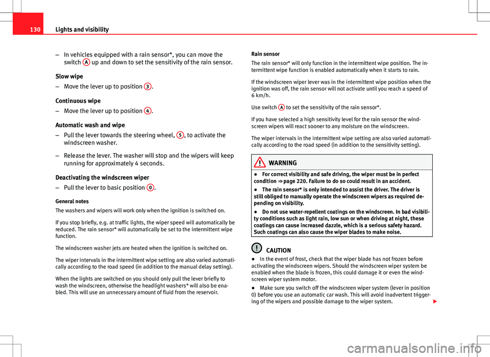
The windscreen wiper lever ⇒ Fig. 99 has the following settings:
Short wipe
– Move the lever down to position 1
to give the windscreen a
short wipe.
Intermittent wipe / Rain sensor* (activate)
– Move the lever up to position 2
.
– Move the switch A
up or down to set the wiper intervals.
Safety FirstOperating InstructionsPractical TipsTechnical Specifications
Page 132 of 325
130Lights and visibility
–In vehicles equipped with a rain sensor*, you can move the
switch A
up and down to set the sensitivity of the rain sensor.
Slow wipe
– Move the lever up to position 3
.
Continuous wipe
– Move the lever up to position 4
.
Automatic wash and wipe
– Pull the lever towards the steering wheel, 5
, to activate the
windscreen washer.
– Release the lever. The washer will stop and the wipers will keep
running for approximately 4 seconds.
Deactivating the windscreen wiper
– Pull the lever to basic position 0
.
General notes
The washers and wipers will work only when the ignition is switched on.
If you stop briefly, e.g. at traffic lights, the wiper speed will automatically be
reduced. The rain sensor* will automatically be set to the intermittent wipe
function.
The windscreen washer jets are heated when the ignition is switched on.
The wiper intervals in the intermittent wipe setting are also varied automati-
cally according to the road speed (in addition to the manual delay setting).
When the lights are switched on you should only pull the lever briefly to
wash the windscreen, otherwise the headlight washers* will also be ena-
bled. This will use an unnecessary amount of fluid from the reservoir. Rain sensor
The rain sensor* will only function in the intermittent wipe position. The in-
termittent wipe function is enabled automatically when it starts to rain.
If the windscreen wiper lever was in the intermittent wipe position when the
ignition was off, the rain sensor will not activate until you reach a speed of
6 km/h.
Use switch
A
to set the sensitivity of the rain sensor*.
If you have selected a high sensitivity level for the rain sensor the wind-
screen wipers will react sooner to any moisture on the windscreen.
The wiper intervals in the intermittent wipe setting are also varied automati-
cally according to the road speed (in addition to the sensitivity setting).
WARNING
● For correct visibility and safe driving, the wiper must be in perfect
condition ⇒ page 220. Failure to do so could result in an accident.
● The rain sensor* is only intended to assist the driver. The driver is
still obliged to manually operate the windscreen wipers as required de-
pending on visibility.
● Do not use water-repellent coatings on the windscreen. In bad visibili-
ty conditions such as light rain, low sun or when driving at night, these
coatings can cause increased dazzle, which is a serious safety hazard.
Such coatings can also cause the wiper blades to make noise.
CAUTION
● In the event of frost, check that the wiper blade has not frozen before
activating the windscreen wipers. Should the windscreen wiper system be
enabled when the blade is frozen, this could damage it or even the wind-
screen wiper system motor.
● Make sure you switch off the windscreen wiper system (lever in position
0) before you use an automatic car wash. This will avoid inadvertent trigger-
ing of the wipers and possible damage to the wiper system.
Page 133 of 325
131
Lights and visibility
Note
● Check that the washer fluid reservoir is full before starting a long jour-
ney. Fill the reservoir ⇒ page 241.
● Worn or dirty wiper blades can cause smearing on the glass which can
also impair the effectiveness of the rain sensor*. Check the condition of
windscreen wiper blades at regular intervals.
Rear window wiper
The windscreen wiper lever also operates the rear window
wiper and the automatic wash and wipe.
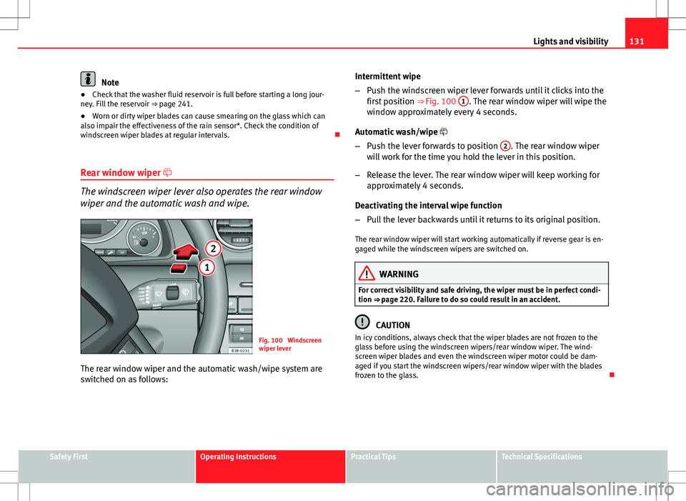
Fig. 100 Windscreen
wiper lever
The rear window wiper and the automatic wash/wipe system are
switched on as follows: Intermittent wipe
–
Push the windscreen wiper lever forwards until it clicks into the
first position ⇒ Fig. 100 1
. The rear window wiper will wipe the
window approximately every 4 seconds.
Automatic wash/wipe
– Push the lever forwards to position 2
. The rear window wiper
will work for the time you hold the lever in this position.
– Release the lever. The rear window wiper will keep working for
approximately 4 seconds.
Deactivating the interval wipe function
– Pull the lever backwards until it returns to its original position.
The rear window wiper will start working automatically if reverse gear is en-
gaged while the windscreen wipers are switched on.
WARNING
For correct visibility and safe driving, the wiper must be in perfect condi-
tion ⇒ page 220. Failure to do so could result in an accident.
CAUTION
In icy conditions, always check that the wiper blades are not frozen to the
glass before using the windscreen wipers/rear window wiper. The wind-
screen wiper blades and even the windscreen wiper motor could be dam-
aged if you start the windscreen wipers/rear window wiper with the blades
frozen to the glass.
Safety FirstOperating InstructionsPractical TipsTechnical Specifications
Page 134 of 325

132Lights and visibility
Headlight washer system
Fig. 101 Headlight with
extended washer jet
With the lights switched on, operate the automatic wash and wipe
⇒ Fig. 99 5
, and keep the lever pulled towards you for at least 1
second.
The headlight washer jets come out of the bumper automatically (under wa-
ter pressure) ⇒ Fig. 101.
Clean off dirt (insects, etc.) from the lenses at regular intervals, for instance
when filling the tank.
To ensure that the system works properly in winter, keep the nozzle holders
free of snow and remove any ice with a de-icer spray. Rear view mirrors
Interior mirror with manual anti-dazzle setting
Normal setting
– Point the lever at the bottom of the mirror forwards.
Anti-dazzle setting for the interior mirror
– Point the lever at the bottom of the mirror to the rear.
Interior mirror with automatic anti-dazzle adjustment*
The automatic anti-dazzle function can be switched on and
off as desired.
Fig. 102 Interior mirror
with anti-dazzle setting:
Indicator lamp and on/off
switch
Page 135 of 325

133
Lights and visibility
Switching off the anti-dazzle function
– Press button A
⇒ Fig. 102. Indicator lamp B goes off.
Switching on the anti-dazzle function
– Press button A
⇒ Fig. 102. Indicator lamp B turns on.
Anti-dazzle function
The anti-dazzle function is activated every time the ignition is switched on.
The green indicator lamp lights up in the mirror housing.
When the anti-dazzle function is enabled, the interior mirror will darken au-
tomatically according to the amount of light it receives. The anti-dazzle
function is disabled if:
● the interior lighting is switched on
● reverse gear is engaged
Sensors for automatic headlights*
When the light switch is set to the AUTO position, the dipped beam head-
lights are switched on and off automatically according to the ambient light
level with the aid of the sensors located in the interior mirror ⇒ page 118.
WARNING
Electrolyte fluid can leak from a broken mirror. This fluid can cause irrita-
tion to the skin, eyes and respiratory organs. Wash thoroughly with clean
water should you come into contact with this fluid. Seek medical assis-
tance if needed!
CAUTION
Electrolyte fluid leaking from a broken mirror can cause damage to plastic
surfaces. Use a sponge or similar to remove the fluid as soon as possible.
Note
● The interior mirror automatic anti-dazzle function* will only work proper-
ly if the sun blind* for the rear window is retracted and if there are no other
objects preventing light from reaching the mirror.
● If you have to stick any type of sticker on the windscreen, do not do so in
front of the sensors. Doing so could prevent the automatic headlight or anti-
dazzle function from working correctly or even from working at all.
Exterior mirrors
The exterior mirrors are adjusted electrically.
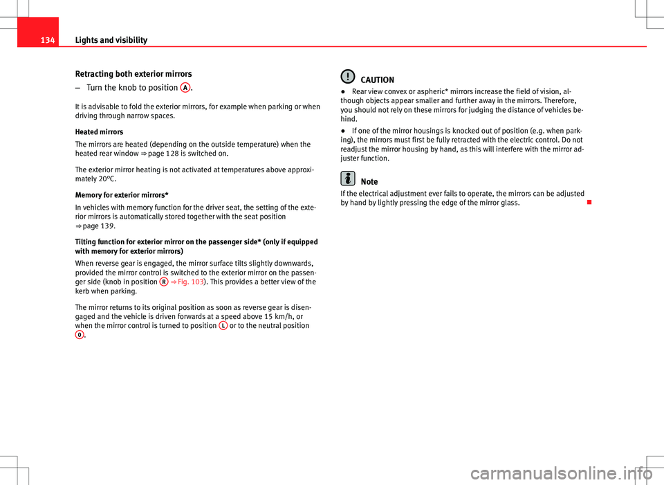
Fig. 103 Detailed view of
the armrest: Adjuster
knob
Adjusting the exterior mirrors
– Turn the adjuster knob to position ⇒
Fig. 103 L
(left exterior
mirror) or position R (right exterior mirror).
– Move the knob as required to adjust the exterior mirror for a
good view behind you.
Safety FirstOperating InstructionsPractical TipsTechnical Specifications
Page 136 of 325
134Lights and visibility
Retracting both exterior mirrors
–Turn the knob to position A
.
It is advisable to fold the exterior mirrors, for example when parking or when
driving through narrow spaces.
Heated mirrors
The mirrors are heated (depending on the outside temperature) when the
heated rear window ⇒ page 128 is switched on.
The exterior mirror heating is not activated at temperatures above approxi-
mately 20°C.
Memory for exterior mirrors*
In vehicles with memory function for the driver seat, the setting of the exte-
rior mirrors is automatically stored together with the seat position
⇒ page 139.
Tilting function for exterior mirror on the passenger side* (only if equipped
with memory for exterior mirrors)
When reverse gear is engaged, the mirror surface tilts slightly downwards,
provided the mirror control is switched to the exterior mirror on the passen-
ger side (knob in position R
⇒ Fig. 103). This provides a better view of the
kerb when parking.
The mirror returns to its original position as soon as reverse gear is disen-
gaged and the vehicle is driven forwards at a speed above 15 km/h, or
when the mirror control is turned to position L
or to the neutral position
0.
CAUTION
● Rear view convex or aspheric* mirrors increase the field of vision, al-
though objects appear smaller and further away in the mirrors. Therefore,
you should not rely on these mirrors for judging the distance of vehicles be-
hind.
● If one of the mirror housings is knocked out of position (e.g. when park-
ing), the mirrors must first be fully retracted with the electric control. Do not
readjust the mirror housing by hand, as this will interfere with the mirror ad-
juster function.
Note
If the electrical adjustment ever fails to operate, the mirrors can be adjusted
by hand by lightly pressing the edge of the mirror glass.
Page 137 of 325
135
Seats and storage compartments
Seats and storage compartments Manual adjustment of the front seats
Seat adjuster controls
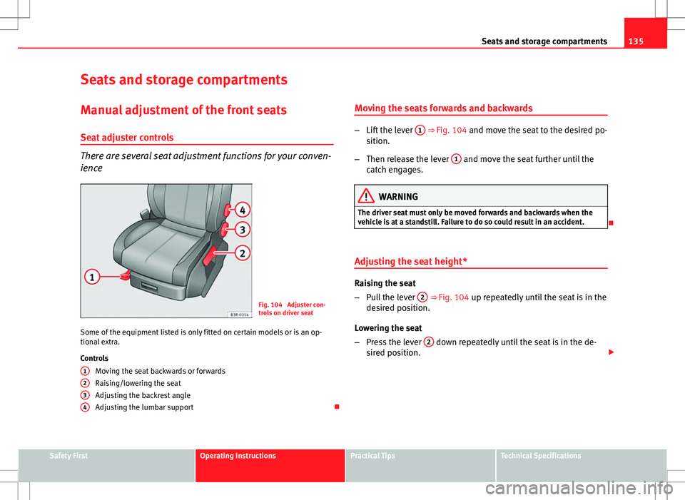
There are several seat adjustment functions for your conven-
ience
Fig. 104 Adjuster con-
trols on driver seat
Some of the equipment listed is only fitted on certain models or is an op-
tional extra.
Controls Moving the seat backwards or forwards
Raising/lowering the seat
Adjusting the backrest angle
Adjusting the lumbar support
1
234
Moving the seats forwards and backwards
–
Lift the lever 1 ⇒ Fig. 104 and move the seat to the desired po-
sition.
– Then release the lever 1
and move the seat further until the
catch engages.
WARNING
The driver seat must only be moved forwards and backwards when the
vehicle is at a standstill. Failure to do so could result in an accident.
Adjusting the seat height*
Raising the seat
– Pull the lever 2
⇒ Fig. 104 up repeatedly until the seat is in the
desired position.
Lowering the seat
– Press the lever 2
down repeatedly until the seat is in the de-
sired position.
Safety FirstOperating InstructionsPractical TipsTechnical Specifications
Page 138 of 325
136Seats and storage compartments
WARNING
● The height of the driver seat must not be adjusted while driving. Fail-
ure to do so could result in an accident.
● Be careful when adjusting the seat height. Injuries can be caused if
the seat height is adjusted without due care and attention.
Adjusting the backrest angle
– Lean forwards to take your weight off the backrest.
– Turn the adjuster wheel 3
⇒ Fig. 104 to set the angle of the
backrest as required.
WARNING
The front backrests must not be reclined for driving. Otherwise, seat
belts and the airbag system might not protect as they should, with the
subsequent danger of injury.
Adjusting lumbar support*
– Do not exert any pressure on the backrest and turn adjuster
wheel 4 ⇒ Fig. 104 to adjust lumbar support.
As you make the adjustments, the curvature of the cushioned area of the
lumbar region becomes more or less acute. In this way, it adapts to the nat-
ural curvature of the spine.
Page 139 of 325

137
Seats and storage compartments
Electric adjustment of front seats*
Adjusting the seat
The arrangement of the switches corresponds with the de-
sign of the seats.
Fig. 105 Front seat: Ad-
juster controls
Fig. 106 Front seat: Seat
adjustment switches
The adjustment switches for the seat and backrest correspond with
the layout, design and operation of the seat. The seats can be ad-
justed merely by pressing the corresponding switch in the required
direction.
Moving the seat forwards / backwards
– Press switch A
⇒ Fig. 105 forwards or backwards 1⇒ Fig. 106 ⇒ .
Raising/lowering the seat
– Press switch A
up or down ⇒ .
Raising/lowering the front part of the seat
– Press the front of switch A
up or down 2 ⇒ .
Raising/lowering the rear part of the seat
– Press the rear of switch A
up or down 3 ⇒ .
Safety FirstOperating InstructionsPractical TipsTechnical Specifications
Page 140 of 325
138Seats and storage compartments
Controls
Seat adjustment
Backrest adjustment
Lumbar support*
WARNING
● The electrical seat adjustment also works when the ignition is off or
when the key is not in the ignition. To avoid accidental injuries, never
leave children unattended in the vehicle.
● For safety reasons, the seat must only be adjusted when the vehicle
is at a standstill. Failure to do so could result in an accident.
● Be careful when adjusting the seat height. Injuries can be caused if
the seat height is adjusted without due care and attention.
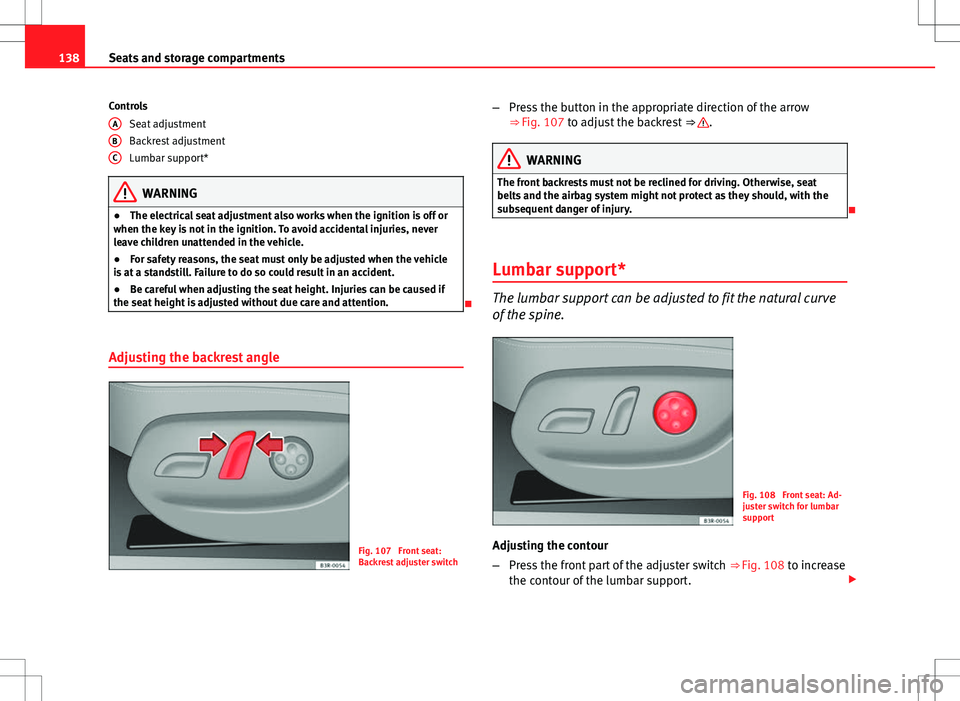
Adjusting the backrest angle
Fig. 107 Front seat:
Backrest adjuster switch
A
BC
–
Press the button in the appropriate direction of the arrow
⇒ Fig. 107 to adjust the backrest ⇒ .
WARNING
The front backrests must not be reclined for driving. Otherwise, seat
belts and the airbag system might not protect as they should, with the
subsequent danger of injury.
Lumbar support*
The lumbar support can be adjusted to fit the natural curve
of the spine.
Fig. 108 Front seat: Ad-
juster switch for lumbar
support
Adjusting the contour
– Press the front part of the adjuster switch ⇒
Fig. 108 to increase
the contour of the lumbar support.