technical specifications Seat Exeo ST 2012 Manual Online
[x] Cancel search | Manufacturer: SEAT, Model Year: 2012, Model line: Exeo ST, Model: Seat Exeo ST 2012Pages: 325, PDF Size: 5.56 MB
Page 165 of 325
163
Air conditioning
CAUTION
β If you suspect that the air conditioner system is damaged, switch over to
ECON mode to prevent further damage and have the system checked by a
specialised workshop.
β Repairs to the air conditioner require specialist knowledge and special
tools. For this reason, please contact a specialised workshop if the system
is not working properly.
Note
β Keep the air intake slots in front of the windscreen clear of snow, ice and
leaves to ensure unimpaired heating and cooling and to prevent the win-
dows misting over.
β The air from the outlets flows through the passenger compartment and
out through the slots below the rear window. Therefore, do not cover these
slots with items of clothing or other objects.
β The air conditioner operates most effectively with the windows and the
sliding/tilting sunroof* closed. However, if the vehicle has heated up after
standing in the sun for some time, the air inside can be cooled more quickly
by opening the windows briefly. ο
Safety FirstOperating InstructionsPractical TipsTechnical Specifications
Page 167 of 325

165
Air conditioning
Button(s)Meaning
ο ο(in the centre)Adjusts blower speed
ο³Air to the windows
οΈAir from the dashboard outlets
ο΄Air to the footwells
The ο³, οΈ and ο΄ buttons (which regulate air distribution) can either be
selected individually or in combination. ο
Automatic mode AUTO
Standard setting for all seasons.
Switching on automatic mode
β It is possible to select interior temperatures from +18Β°C (64Β°F)
to +29Β°C (86Β°F).
β Press the AUTO
ββ
Fig. 139 button.
The automatic mode maintains a constant temperature inside the vehicle
and dehumidifies the air. Air temperature, air delivery and air distribution
are regulated automatically to reach the desired interior temperature as
quickly as possible, and then to maintain this temperature. The system au-
tomatically compensates for any variations in the outside temperature and
for the effect of direct sunlight.
The automatic temperature regulation only operates at temperature settings
between +18Β°C and +29Β°C. If a temperature below +18Β°C is selected, LO ap-
pears on the display. If a temperature is selected which is higher than +29Β°C, the display will show
HI. In the maximum and minimum settings, the
climate control operates continuously with maximum cooling or heating
output and the temperature is not regulated automatically. The temperature
is not regulated.
Note
By keeping the AUTO button on the driver side pressed for several seconds,
the temperature of the passenger side can be set to the temperature of the
driver side or vice versa. The display indicates the new temperature value. ο
Selecting the temperature -
+
Separate temperatures can be selected for the driver and
front passenger sides.
β Press the -
or + buttons below the displays
ββFig. 139 until
the desired temperature is selected for the driver side or front
passenger side.
The currently selected temperature setting is shown in the display above
the buttons.
By keeping the AUTO
button on the driver side pressed for several seconds,
the temperature of the passenger side can be set to the temperature of the
driver side or vice versa. The display indicates the new temperature value.
The previous temperature setting can be restored by resetting the display
on the driver or passenger side as required. ο
Safety FirstOperating InstructionsPractical TipsTechnical Specifications
Page 169 of 325

167
Air conditioning
Note
If the diode on the ECON button continues to light up when the ECON mode
has been switched off (i.e. the air conditioner has been switched on) this is
due to a defect in one of the air conditioner components. If a malfunction
should occur, please contact a specialised workshop. ο
Air recirculation: automatic activation* ο±
If the outside air is polluted by diesel and petrol emissions,
an air quality sensor in the vehicle will automatically switch
on the air recirculation.
Fig. 140 Button for auto-
matic air recirculation
Activating air recirculation mode
β Press the button ο±
ββ
Fig. 140.
Deactivating air recirculation mode
β Press the ο±
button again or β
Press the AUTO
button or
β Press button ο
.
The automatic air recirculation mode should normally be left switched on at
all times.
The system is ready to operate approx. 30 seconds after the engine ignition
key has been turned. During this initial period, fresh air is fed into the vehi-
cle.
If the air purity sensor in the air conditioner detects a certain concentration
of fumes in the outside air, the control unit will either pass the incoming air
through the pollution filter or automatically switch on the air recirculation. If
there is a high concentration of pollution in the outside air, the air condi-
tioner automatically switches to air recirculation and the supply of air from
the outside is cut off. As soon as the level of pollution decreases, air is fed
into the vehicle from the outside again.
The automatic air recirculation operates for a maximum period of 12 mi-
nutes. If the windows mist up when the automatic air recirculation is on,
press the ο
button immediately.
The automatic air recirculation switches itself off under certain circumstan-
ces (for instance if ο
or ο° is selected). In βECONβ and at temperatures
lower than approx. 8Β°C below zero, the automatic air recirculation mode is
limited to 12 seconds. ο
Safety FirstOperating InstructionsPractical TipsTechnical Specifications
Page 171 of 325
169
Air conditioning
Air outlets
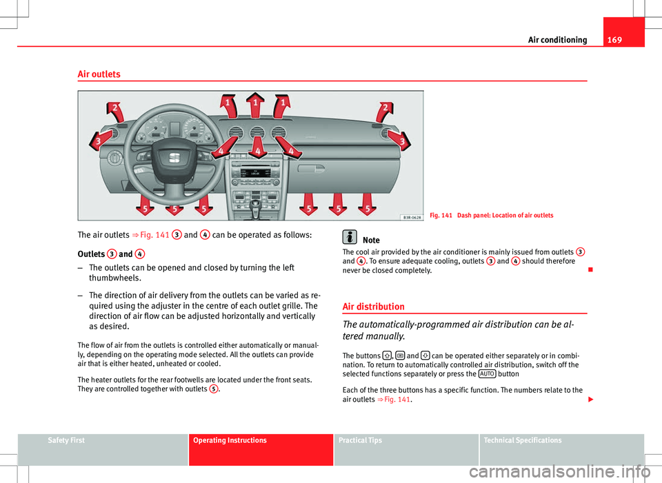
Fig. 141 Dash panel: Location of air outlets
The air outlets ββFig. 141 3
and 4 can be operated as follows:
Outlets 3
and 4
β
The outlets can be opened and closed by turning the left
thumbwheels.
β The direction of air delivery from the outlets can be varied as re-
quired using the adjuster in the centre of each outlet grille. The
direction of air flow can be adjusted horizontally and vertically
as desired.
The flow of air from the outlets is controlled either automatically or manual-
ly, depending on the operating mode selected. All the outlets can provide
air that is either heated, unheated or cooled.
The heater outlets for the rear footwells are located under the front seats.
They are controlled together with outlets 5
.
Note
The cool air provided by the air conditioner is mainly issued from outlets 3
and 4. To ensure adequate cooling, outlets 3 and 4 should therefore
never be closed completely. ο
Air distribution
The automatically-programmed air distribution can be al-
tered manually.
The buttons ο³
, οΈ and ο΄ can be operated either separately or in combi-
nation. To return to automatically controlled air distribution, switch off the
selected functions separately or press the AUTO
button
Each of the three buttons has a specific function. The numbers relate to the
air outlets ββFig. 141. ο£
Safety FirstOperating InstructionsPractical TipsTechnical Specifications
Page 173 of 325
171
Air conditioning
If the air recirculation mode is on when you switch off the engine, the air
conditioner will automatically switch to fresh air ventilation. ο
Auxiliary heater*
Diesel vehicles are fitted with an auxiliary heater 1)
to raise the temperature
of the interior as quickly as possible. At outdoor temperatures below +5Β°C
and with the engine running, the supplementary heating will switch on and
off automatically depending on the temperature of the coolant.
In order to save fuel, the auxiliary heater can be can be switched off by brief-
ly pressing the ο
οοο
button on the air conditioner. οSeat heating*
The surface and backrest of the front seats can be electrical-
ly heated.
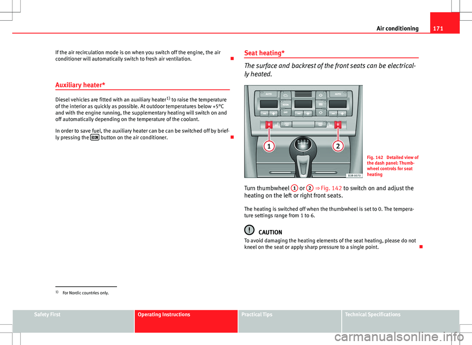
Fig. 142 Detailed view of
the dash panel: Thumb-
wheel controls for seat
heating
Turn thumbwheel 1
or 2 ββFig. 142 to switch on and adjust the
heating on the left or right front seats.
The heating is switched off when the thumbwheel is set to 0. The tempera-
ture settings range from 1 to 6.
CAUTION
To avoid damaging the heating elements of the seat heating, please do not
kneel on the seat or apply sharp pressure to a single point. ο
1)
For Nordic countries only.
Safety FirstOperating InstructionsPractical TipsTechnical Specifications
Page 175 of 325

173
Driving
The Electronic Stability Control (ESC) contains the electronic differential lock
(EDL) and the traction control system (ASR). The ESC works together with
the ABS. If a fault in the ABS occurs, both warning lamps light up, but if the
ESC fails, only the ESC warning lamp lights up.
The ESC system is started automatically when the engine is started.
The ESC system is always active and cannot be switched off. The ESC switch
only switches the ASR off.
The ASR can be deactivated when wheel spin is desirable.
For example:
β When driving with snow chains.
β When driving in deep snow or on loose surfaces.
β When the vehicle is stuck, to rock it backwards and forwards.
Press the button to switch the ASR back on when you no longer need wheel
spin.
Situations in which the warning lamp lights οΆ
β
On switching the ignition on, it lights up for about two seconds to carry
out a function control.
β The warning lamp will start flashing when the vehicle is moving if the
ESC or the ASR is activated.
β It will light up continuously if there is a fault in the ESC.
WARNING
β Do not forget that the electronic stability control ESC cannot defy the
laws of physics. This should be kept in mind, particularly on slippery and
wet roads and when towing a trailer.
β Always adapt your driving style to suit the condition of the roads and
the traffic situation. The greater safety provided by the ESC should not
encourage you to run any risks.
β Please refer to the corresponding warning notes on ESC in
ββpage 195, Intelligent technology.
ο
Ignition lock Ignition key positions
The ignition key is used to start and stop the engine.
Fig. 145 Ignition key po-
sitions ο£
Safety FirstOperating InstructionsPractical TipsTechnical Specifications
Page 177 of 325
175
Driving
β Manual gearbox: Push the clutch pedal all the way down.
β Move the gear lever into neutral (automatic gearbox: selector
lever to P or N) ββ
.
β Turn the ignition key to position 3
without pressing the accel-
erator.
β Release the ignition key as soon as the engine starts (the start-
er motor must not be allowed to run on with the engine).
Vehicles with a diesel engine:
β Use the foot brake.
β Manual gearbox: Push the clutch pedal all the way down. Other-
wise, the engine will not start.
β Move the gear lever into neutral (automatic gearbox: selector
lever to P or N) ββ
.
β Turn the ignition key to position 2
. The pre-heating indicator
light ο€ comes on while the glow plugs are preheating.
β When the indicator light ο€ goes out, turn the ignition key to
position 3
. Do not press the accelerator.
β Having completed the previous action the key can be released
immediately, it will return to position 2
and the engine will
have started.
When starting a very cold engine, it may be a little noisy for the first few sec-
onds until oil pressure has built up in the hydraulic valve compensators.
This is quite normal, and no cause for concern.
If the engine fails to start straight away, stop after 10 seconds and try again
after about half a minute. Glow plug system*
To assist starting at low temperatures,
diesel engines are equipped with a
glow plug preheating system. The preheating time depends on the coolant
temperature and the outside temperature. Start the engine as soon as the
glow plug indicator light ο€ goes out.
When the engine is warm or at outside temperatures above +8Β°C the glow
plug indicator lamp will only light up for about one second. This means that
the engine can be started immediately.
If the engine will not start...
β ββpage 293
β ββpage 297
β ββpage 230, Refuelling
WARNING
Never run the engine in confined spaces, as the exhaust gases are poi-
sonous.
CAUTION
Avoid high engine speeds, full throttle and extreme load conditions until
the engine has reached its normal operating temperature, otherwise this
can damage the engine.
For the sake of the environment
Do not warm up the engine by running the engine with the vehicle station-
ary. Start immediately. This will help avoid unnecessary exhaust emissions. ο
Stopping the engine
β Turn the ignition key to position 1 ββFig. 146.ο£
Safety FirstOperating InstructionsPractical TipsTechnical Specifications
Page 179 of 325
177
Driving
β The Start-Stop System is manually deactivated.
β The windscreen de-mist function is turned on.
β The temperature of the passenger compartment exceeds the comfort
limits (button ECON
should not be selected).
β If more than 50% of the airflow that the fan can supply is ordered.
β Temperature setting HI or LO is selected.
β The engine coolant temperature is insufficient.
β The alternator is faulty, for example the V-belt has ruptured.
β If any of the conditions described in the previous section are not fulfil-
led.
WARNING
Never allow the vehicle to move with the engine off for any reason. You
could lose control of your vehicle. This could cause an accident and seri-
ous injury.
β Power steering does not work when the engine is not running. That is
why it is much more difficult to turn the steering wheel.
β Disconnect the Start-Stop system when driving through water (ford-
ing streams, etc.).
Note
β For vehicles with the Start-Stop function and a manual gearbox, when
the engine is started, the clutch must be pressed.
β When the conditions for the Start-Stop function are not fulfilled, the in-
strument panel displays the Start-Stop indicator dimmed.
β If the steering wheel is turned more than 270Β°, Stop will not function;
however, the angle of steering wheel turn does not affect starting the vehi-
cle. οActivating and deactivating the Start-Stop function
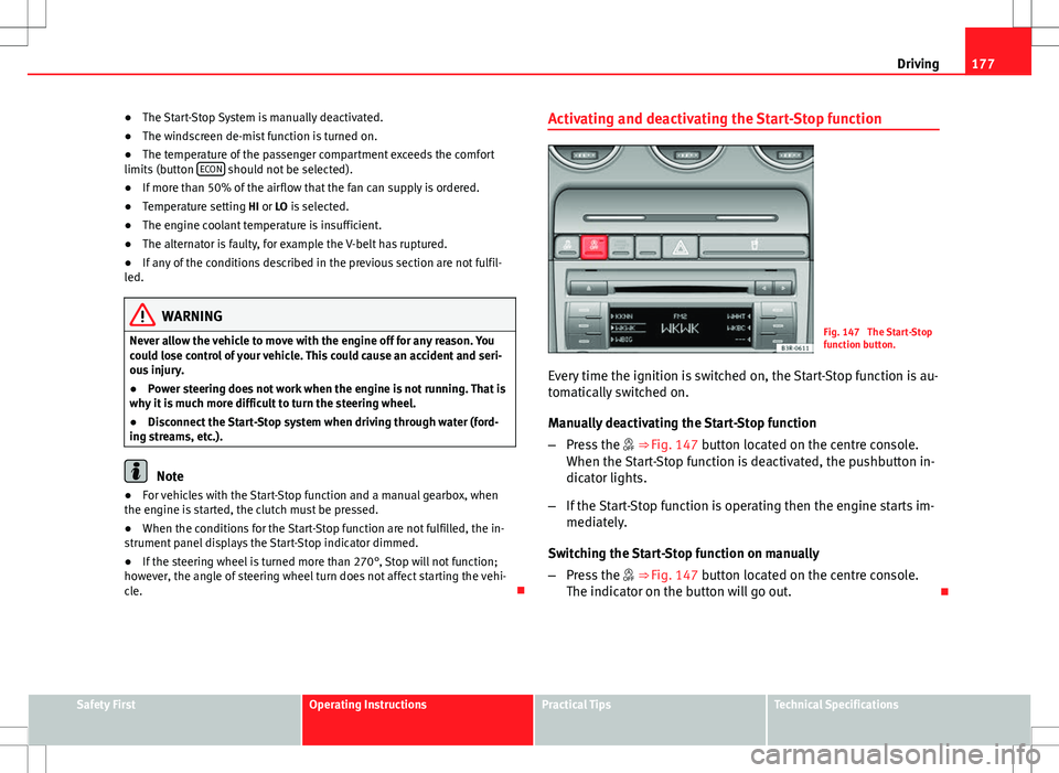
Fig. 147 The Start-Stop
function button.
Every time the ignition is switched on, the Start-Stop function is au-
tomatically switched on.
Manually deactivating the Start-Stop function
β Press the ο§ ββFig. 147 button located on the centre console.
When the Start-Stop function is deactivated, the pushbutton in-
dicator lights.
β If the Start-Stop function is operating then the engine starts im-
mediately.
Switching the Start-Stop function on manually
β Press the ο§ ββFig. 147 button located on the centre console.
The indicator on the button will go out. ο
Safety FirstOperating InstructionsPractical TipsTechnical Specifications
Page 181 of 325
179
Driving
Warnings
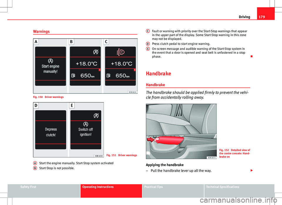
Fig. 150 Driver warnings
Fig. 151 Driver warnings
Start the engine manually. Start-Stop system activated
Start-Stop is not possible.
A
B
Fault or warning with priority over the Start-Stop warnings that appear
in the upper part of the display. Some Start-Stop warning in this zone
may not be displayed.
Press clutch pedal to start engine warning.
On-screen message and audible warning of the Start-Stop system in
the event that a door is opened and seat belt is unfastened in a stop
phase.
ο
Handbrake Handbrake
The handbrake should be applied firmly to prevent the vehi-
cle from accidentally rolling away.
Fig. 152 Detailed view of
the centre console: Hand-
brake on
Applying the handbrake
β Pull the handbrake lever up all the way. ο£
C
DE
Safety FirstOperating InstructionsPractical TipsTechnical Specifications
Page 183 of 325

181
Driving
Parking aid acoustic system
General notes
Various systems are available to help you when parking or manoeuvring in
tight spaces, depending on the equipment fitted on your vehicle.
The SEAT Parking System gives an acoustic warning if there are any obsta-
cles behind your vehicle ββpage 181.
When you are parking, SEAT Parking System Plus warns you acoustically
and optically about obstacles in front of and behind the vehicle
ββpage 182.
Note
To ensure the acoustic parking aid works properly, the sensors must be kept
clean and free of snow and ice. ο
SEAT Parking System*
SEAT Parking System is an acoustic parking aid.
Sensors are located in the rear bumper. When the sensors detect an obsta-
cle, you are alerted by acoustic signals. The measuring range of the sensors
starts at approximately:
RearSide0.60 mCentre1.60 m
The acoustic signals sound with increasing frequency as you approach the
obstacle. When the vehicle is less than 0.30 m away from the obstacle, the
warning tone will sound continuously. Do not drive on! The volume of the warning beeps will be gradually reduced after about 4
seconds if the vehicle remains at a constant distance from a detected obsta-
cle (it does not affect the permanent acoustic signal).
The parking aid is switched on automatically when reverse gear is engaged.
You will hear a brief confirmation tone.
WARNING
β The parking aid is not a replacement for driver awareness. The driver
is personally responsible for safe parking and other manoeuvres.
β The sensors have blind spots in which obstacles are not registered.
Always look out for small children and animals because the system will
not always detect them. Always pay attention when reversing to avoid ac-
cidents.
β Always keep a close eye on the area around the vehicle and make full
use of the rear view mirrors.
CAUTION
Please note that low obstacles detected by the system may no longer be
registered by the sensors as the vehicle moves closer, so the system will not
give any further warning. Certain kinds of obstacles (such as wire fences,
chains, thin painted posts or trailer draw bars, etc) may not always be de-
tected by the system, so take care not to damage the vehicle in such cases.
Note
β Please refer to the notes on towing ββpage 183. ο
Safety FirstOperating InstructionsPractical TipsTechnical Specifications