battery Seat Exeo ST 2013 Owner's manual
[x] Cancel search | Manufacturer: SEAT, Model Year: 2013, Model line: Exeo ST, Model: Seat Exeo ST 2013Pages: 327, PDF Size: 5.07 MB
Page 6 of 327
Trailer towing . . . . . . . . . . . . . . . . . . . . . . . . . . . . . . 208
Trailer towing . . . . . . . . . . . . . . . . . . . . . . . . . . . . . 208
Removable towing bracket . . . . . . . . . . . . . . . . . . 211
Vehicle maintenance and cleaning . . . . . . . . . 218
General notes . . . . . . . . . . . . . . . . . . . . . . . . . . . . 218
Care of the vehicle exterior . . . . . . . . . . . . . . . . . . 219
Vehicle interior maintenance . . . . . . . . . . . . . . . . 224
Accessories, replacement of parts and
modifications . . . . . . . . . . . . . . . . . . . . . . . . . . . . . 230
Accessories and spare parts . . . . . . . . . . . . . . . . 230
Technical modifications . . . . . . . . . . . . . . . . . . . . 230
Mobile phones and two-way radios . . . . . . . . . . . 231
Athermic windscreen* . . . . . . . . . . . . . . . . . . . . . 231
Checking and refilling levels . . . . . . . . . . . . . . . 232
Refuelling . . . . . . . . . . . . . . . . . . . . . . . . . . . . . . . 232
Petrol . . . . . . . . . . . . . . . . . . . . . . . . . . . . . . . . . . . 233
Diesel . . . . . . . . . . . . . . . . . . . . . . . . . . . . . . . . . . . 234
Bonnet . . . . . . . . . . . . . . . . . . . . . . . . . . . . . . . . . . 235
Engine oil . . . . . . . . . . . . . . . . . . . . . . . . . . . . . . . . 237
Cooling system . . . . . . . . . . . . . . . . . . . . . . . . . . . 240
Washer fluid and windscreen wiper blades . . . . 243
Brake fluid . . . . . . . . . . . . . . . . . . . . . . . . . . . . . . . 246
Vehicle battery . . . . . . . . . . . . . . . . . . . . . . . . . . . 247
Wheels and tyres . . . . . . . . . . . . . . . . . . . . . . . . . . 251
Wheels . . . . . . . . . . . . . . . . . . . . . . . . . . . . . . . . . . 251
If and when . . . . . . . . . . . . . . . . . . . . . . . . . . . . . . . 261
Tools, tyre repair kit and spare wheel . . . . . . . . . 261
Changing a wheel . . . . . . . . . . . . . . . . . . . . . . . . . 264
Tyre repair* (Tyre-Mobility-System) . . . . . . . . . . . 268
Fuses . . . . . . . . . . . . . . . . . . . . . . . . . . . . . . . . . . . 272
Bulbs . . . . . . . . . . . . . . . . . . . . . . . . . . . . . . . . . . . 274
Changing bulbs. Halogen headlights . . . . . . . . . 275
Changing bulbs. Bi-Xenon AFS headlights . . . . . 281
Changing tail light bulbs (on side panel) . . . . . . 285
Changing tail light bulbs (on rear lid) . . . . . . . . . 290
Side turn signals . . . . . . . . . . . . . . . . . . . . . . . . . . 293 Luggage compartment lights . . . . . . . . . . . . . . . . 294
Registration light . . . . . . . . . . . . . . . . . . . . . . . . . . 294
Sun visor light . . . . . . . . . . . . . . . . . . . . . . . . . . . . 295
Jump-starting . . . . . . . . . . . . . . . . . . . . . . . . . . . . . 295
Towing and tow-starting . . . . . . . . . . . . . . . . . . . . 299
Technical Specifications . . . . . . . . . . . 302
Description of specifications . . . . . . . . . . . . . . . 302
Important information . . . . . . . . . . . . . . . . . . . . . 302
Information on fuel consumption . . . . . . . . . . . . 303
Towing a trailer . . . . . . . . . . . . . . . . . . . . . . . . . . . 305
Wheels . . . . . . . . . . . . . . . . . . . . . . . . . . . . . . . . . . 305
Technical specifications . . . . . . . . . . . . . . . . . . . . 306
Engine specifications . . . . . . . . . . . . . . . . . . . . . . 306
Dimensions and capacities . . . . . . . . . . . . . . . . . 314
Index . . . . . . . . . . . . . . . . . . . . . . . . . . . . . . . . . . . 315
4Table of Contents
Page 74 of 327
72Cockpit
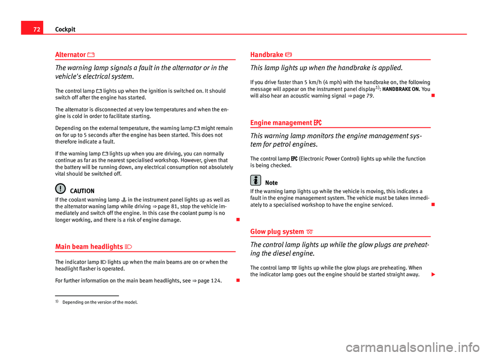
Alternator
The warning lamp signals a fault in the alternator or in the
vehicle's electrical system.
The control lamp lights up when the ignition is switched on. It should
switch off after the engine has started.
The alternator is disconnected at very low temperatures and when the en-
gine is cold in order to facilitate starting.
Depending on the external temperature, the warning lamp might remain
on for up to 5 seconds after the engine has been started. This does not
therefore indicate a fault.
If the warning lamp lights up when you are driving, you can normally
continue as far as the nearest specialised workshop. However, given that
the battery will be running down, any electrical consumption not absolutely
vital should be switched off.
CAUTION
If the coolant warning lamp in the instrument panel lights up as well as
the alternator waning lamp while driving ⇒ page 81, stop the vehicle im-
mediately and switch off the engine. In this case the coolant pump is no
longer working, and there is a risk of engine damage.
Main beam headlights
The indicator lamp lights up when the main beams are on or when the
headlight flasher is operated.
For further information on the main beam headlights, see ⇒ page 124.Handbrake
This lamp lights up when the handbrake is applied.
If you drive faster than 5 km/h (4 mph) with the handbrake on, the following
message will appear on the instrument panel display 1)
: HANDBRAKE ON. You
will also hear an acoustic warning signal ⇒ page 79.
Engine management
This warning lamp monitors the engine management sys-
tem for petrol engines.
The control lamp (Electronic Power Control) lights up while the function
is being checked.
Note
If the warning lamp lights up while the vehicle is moving, this indicates a
fault in the engine management system. The vehicle must be taken immedi-
ately to a specialised workshop to have the engine serviced.
Glow plug system
The control lamp lights up while the glow plugs are preheat-
ing the diesel engine. The control lamp lights up while the glow plugs are preheating. When
the indicator lamp goes out the engine should be started straight away.
1)
Depending on the version of the model.
Page 80 of 327
78Cockpit
Service reminder
The instrument panel controls the distance travelled every day. It calculates
the average of these distances travelled and activates the service reminder
sufficiently in advance.
The display reverts back to the standard display after about 5 seconds. The
remaining distance to the next service is updated every time the ignition is
switched on, until the service becomes due.
Service due
When a service is due, SERVICE! will appear in the display immediately after
you switch on the ignition. The display reverts back to the standard display
after about 5 seconds.
Resetting the display
The display is reset by the specialised workshop after the service has been
carried out. The service interval will be set to a LongLife Service (flexible
service interval) or Inspection Service (fixed service interval), depending on
which engine oil is used. It is only possible to reset the display via the in-
strument panel when an oil change is performed; in this case the display
can only be reset to a fixed service interval of 15 000 km. Proceed as fol-
lows:
● Switch the ignition off.
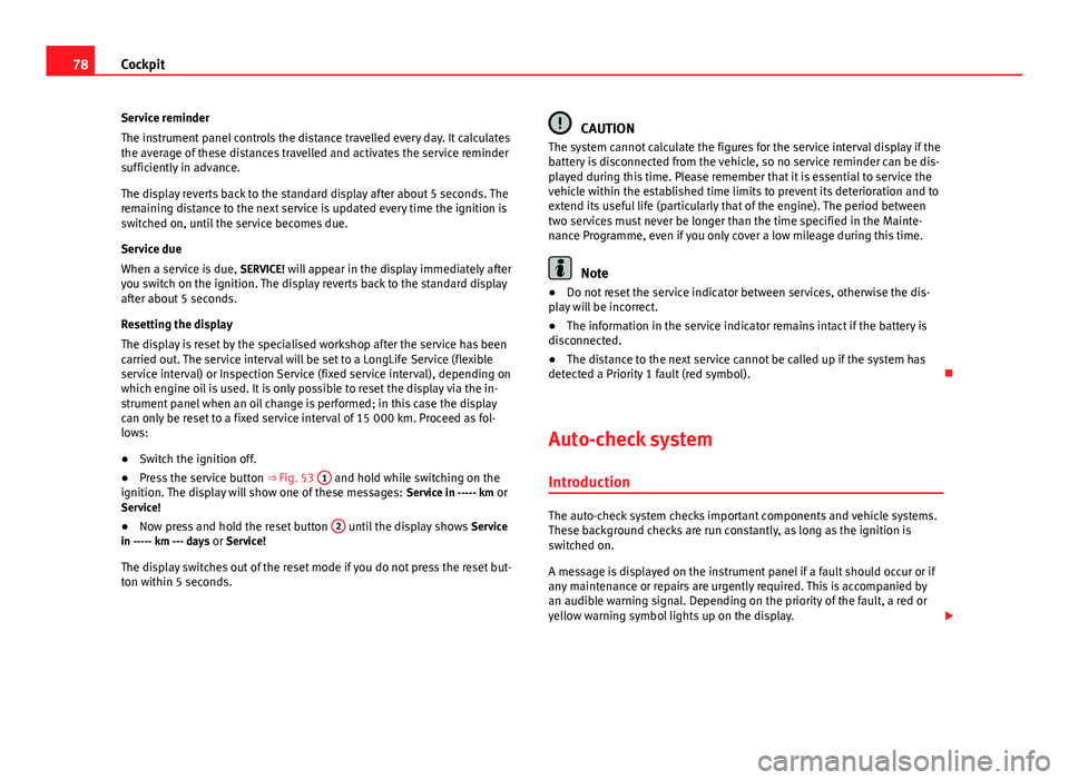
● Press the service button ⇒ Fig. 53 1
and hold while switching on the
ignition. The display will show one of these messages: Service in ----- km or
Service!
● Now press and hold the reset button 2
until the display shows
Service
in ----- km --- days or Service!
The display switches out of the reset mode if you do not press the reset but-
ton within 5 seconds.
CAUTION
The system cannot calculate the figures for the service interval display if the
battery is disconnected from the vehicle, so no service reminder can be dis-
played during this time. Please remember that it is essential to service the
vehicle within the established time limits to prevent its deterioration and to
extend its useful life (particularly that of the engine). The period between
two services must never be longer than the time specified in the Mainte-
nance Programme, even if you only cover a low mileage during this time.
Note
● Do not reset the service indicator between services, otherwise the dis-
play will be incorrect.
● The information in the service indicator remains intact if the battery is
disconnected.
● The distance to the next service cannot be called up if the system has
detected a Priority 1 fault (red symbol).
Auto-check system Introduction
The auto-check system checks important components and vehicle systems.
These background checks are run constantly, as long as the ignition is
switched on.
A message is displayed on the instrument panel if a fault should occur or if
any maintenance or repairs are urgently required. This is accompanied by
an audible warning signal. Depending on the priority of the fault, a red or
yellow warning symbol lights up on the display.
Page 84 of 327
82Cockpit
Engine oil level correct
If the symbol flashes and the engine oil level is correct, obtain profes-
sional assistance. Do not drive on! Do not continue to run the engine, even
at idle speed .
Note
The oil pressure warning lamp is not an indicator for the oil level. The oil
level should therefore be checked regularly, preferably every time you fill
the tank.
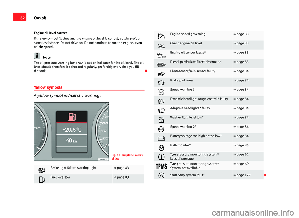
Yellow symbols
A yellow symbol indicates a warning.
Fig. 56 Display: Fuel lev-
el low
Brake light failure warning light⇒ page 83
Fuel level low⇒ page 83
Engine speed governing⇒ page 83
Check engine oil level⇒ page 83
Engine oil sensor faulty*⇒ page 83
Diesel particulate filter* obstructed⇒ page 83
Photosensor/rain sensor faulty⇒ page 84
Brake pad worn⇒ page 84
Speed warning 1⇒ page 84
Dynamic headlight range control* faulty⇒ page 84
Adaptive headlights* faulty⇒ page 84
Washer fluid level low*⇒ page 84
Speed warning 2*⇒ page 84
Battery voltage too high or too low*⇒ page 84
Bulb monitor*⇒ page 85
Tyre pressure monitoring system*
Loss of pressure⇒ page 92
Tyre pressure monitoring system*
System not available⇒ page 69
Start-Stop system fault*⇒ page 179
Page 86 of 327
84Cockpit
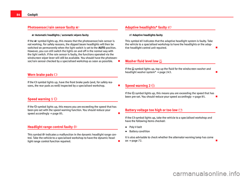
Photosensor/rain sensor faulty
Automatic headlights / automatic wipers faulty
If the symbol lights up, this means that the photosensor/rain sensor is
not working. For safety reasons, the dipped beam headlights will then be
switched on permanently when the light switch is set to the AUTO position.
However, you can still switch the lights on and off in the normal way with
the light switch. If the rain sensor is faulty, the functions operated via the
windscreen wiper lever will still be available. You should have the photosen-
sor/rain sensor checked by a specialised workshop as soon as possible.
Worn brake pads
If the symbol lights up, have the front brake pads (and, for safety rea-
sons, the rear pads as well) inspected by a specialised workshop.
Speed warning 1
If the symbol lights up, this means you are exceeding the speed that has
been pre-set with the speed warning function. You should reduce your
speed accordingly ⇒ page 85.
Headlight range control faulty
This symbol indicates a malfunction in the dynamic headlight range con-
trol. Take the vehicle to a specialised workshop to have the dynamic head-
light range control function repaired. Adaptive headlights* faulty
Adaptive headlights faulty
This symbol indicates that the adaptive headlight system is faulty. Take
the vehicle to a specialised workshop to have the headlights or the adap-
tive headlight control unit repaired.
Washer fluid level low
If the symbol lights up, top up the fluid for the windscreen washer and
headlight washer system* ⇒ page 243.
Speed warning 2
If the symbol lights up, this means you are exceeding the speed that has
been pre-set. You should reduce your speed accordingly ⇒ page 85.
Battery voltage too high or too low
If the symbol lights up, take the vehicle to a specialised workshop and
have the following items checked:
● Poly V-belt
● Battery condition
It is also advisable to check whether the alternator warning lamp has come
on ⇒ page 72.
Page 91 of 327
89
Cockpit
Driving time warning
After 2 hours of continuous driving, the display automatically switches over
to the driving time display of 2:00. At the same time the driving time display
starts flashing. This is to remind the driver to take a break.
The driving time warning can be switched off by briefly pressing the func-
tion selector switch or the Reset
button ⇒ Fig. 61.
If you continue driving or take a break for less than 10 minutes, the driving
time warning will switch on once again when the total driving time is 4:00
hours, 6:00 hours, etc. However, if you take a break for more than 10 mi-
nutes, the driving time warning clock will be erased.
Distance covered
This display shows the distance you have covered since the memory was
last cancelled. The longest possible distance which can be recorded is
9999.9 km.
Note
● The displays for fuel consumption (average and instantaneous), dis-
tance to empty and speed are shown in metric units.
● The information in the memory is lost if the battery is disconnected. Operation
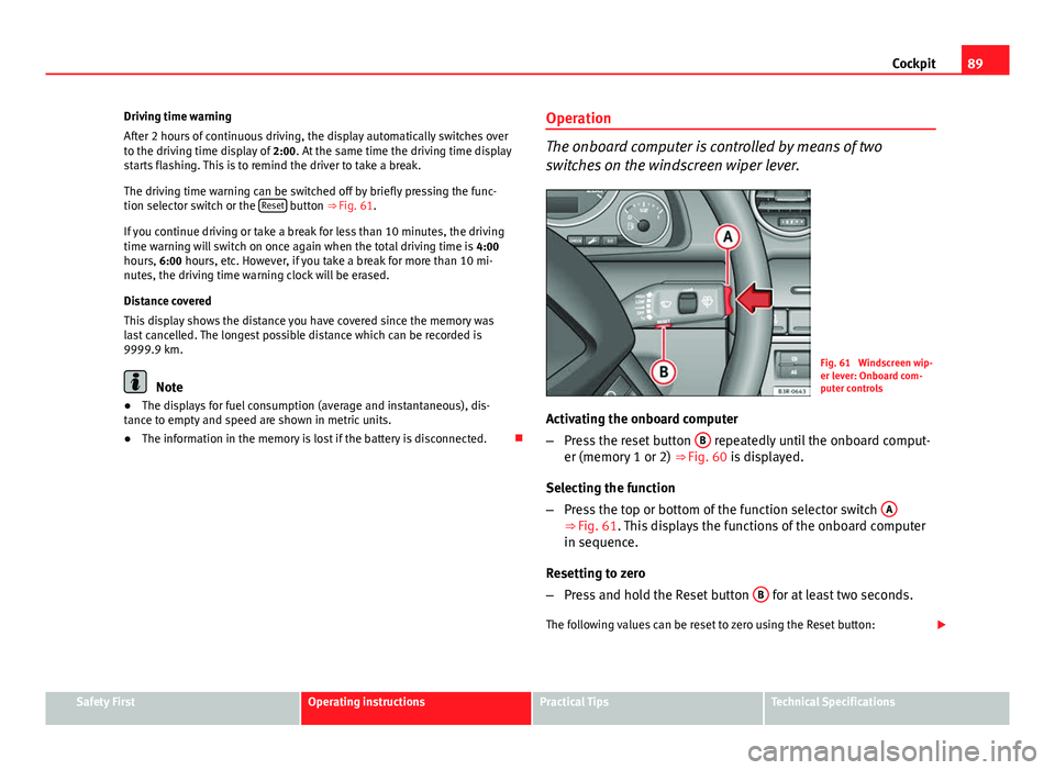
The onboard computer is controlled by means of two
switches on the windscreen wiper lever.
Fig. 61 Windscreen wip-
er lever: Onboard com-
puter controls
Activating the onboard computer
– Press the reset button B
repeatedly until the onboard comput-
er (memory 1 or 2) ⇒ Fig. 60 is displayed.
Selecting the function
– Press the top or bottom of the function selector switch A
⇒ Fig. 61. This displays the functions of the onboard computer
in sequence.
Resetting to zero
– Press and hold the Reset button B
for at least two seconds.
The following values can be reset to zero using the Reset button:
Safety FirstOperating instructionsPractical TipsTechnical Specifications
Page 92 of 327
90Cockpit
● Journey duration
● Distance covered
● Average fuel consumption
● Average speed
The onboard computer can only be operated when the ignition is switched
on. When the ignition is switched on, the display shows the function that
was last selected.
As well as the figures from the onboard computer (1 or 2), the display can
also show information from the navigation system*. Press the Reset button B
briefly to switch back and forward between these displays.
Note
● If you keep the Reset button pressed for longer than two seconds, it will
reset the currently displayed figure to zero (for instance average fuel con-
sumption).
● Faults detected by the auto-check control will be displayed even if the
display is off.
● The information in the memory is lost if the battery is disconnected.
Page 102 of 327
100Opening and closing
2 remote control keys
In certain European markets, vehicles with alarm are equipped with 2 re-
mote control keys.
WARNING
● Always take the key with you when leaving the vehicle, even if you
only intend to be gone for a short time. This is particularly important if
there are children in the vehicle, as they might otherwise be able to start
the engine or use power-operated equipment (e.g. the electric windows),
which could cause injuries.
● Wait for the vehicle to come to a standstill before removing the igni-
tion key from the lock! Otherwise, the steering lock could engage sud-
denly, causing an accident.
Indicator light on the remote control key
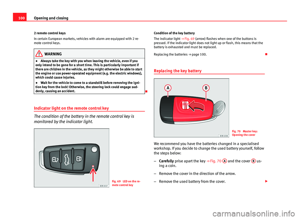
The condition of the battery in the remote control key is
monitored by the indicator light.
Fig. 69 LED on the re-
mote control key Condition of the key battery
The indicator light
⇒ Fig. 69 (arrow) flashes when one of the buttons is
pressed. If the indicator light does not light up or flash, this means that the
battery is exhausted and must be replaced.
Replacing the batteries ⇒ page 100.
Replacing the key battery
Fig. 70 Master key:
Opening the cover
We recommend you have the batteries changed in a specialised
workshop. If you decide to change the used battery yourself, follow
the steps below:
– Carefully prise apart the key ⇒ Fig. 70 A
and the cover B us-
ing a coin.
– Remove the cover in the direction of the arrow.
– Remove the used battery from the cover.
Page 103 of 327
101
Opening and closing
– Insert the new battery. Make sure that the “+” symbol on the
battery is facing downwards. The correct polarity is indicated on
the cover.
– After inserting the battery, align the cover and key and press
the two parts together.
For the sake of the environment
Used batteries must be disposed of at an appropriate waste facility or
through an authorised service, given that their components can affect the
environment.
Note
● The system must be re-synchronised after each battery replacement to
be able to lock and unlock the vehicle using the remote control
⇒ page 109.
● The new battery must be of the same type as the original.
Electronic immobiliser
The electronic immobiliser is designed to prevent unauthor-
ised persons from starting up the vehicle.
There is an electronic chip inside the key which automatically deactivates
the immobiliser when the key is inserted into the ignition lock. The electron-
ic immobiliser is enabled automatically when the ignition key is removed
from the ignition lock after coming to a stop.
If an uncoded key is used, the message SAFE* will appear in the trip record-
er display.
Note
● The engine can only be started using an original SEAT key with the cor-
rect code.
● It may not be possible to start the engine with the key if there is another
ignition key from a different make of vehicle on the same key tab.
Central locking system
Description
The central locking system enables you to lock and unlock
all the doors, the rear lid and the tank flap together. The central locking system on your vehicle locks and unlocks all the doors
and the tank flap simultaneously. The rear lid is unlocked when the vehicle
is opened. However, the handle must be used to open it. The vehicle can be
locked and unlocked using the remote control ⇒ page 108 or by turning the
key in the lock in the driver door.
The windows can also be centrally opened or closed using the central lock-
ing system ⇒ page 114. The sunroof* can be closed but not opened using
the central locking system.
The central locking system is combined with an anti-theft security system.
If the vehicle is locked with the key from the outside, the interior opening
levers stop working, which prevents unauthorised persons from entering
the vehicle.
Should the central locking system fail to work, you can activate all the locks
individually.
Safety FirstOperating instructionsPractical TipsTechnical Specifications
Page 110 of 327
108Opening and closing
Activating the childproof lock
–Turn the key in the direction of the arrow ⇒ Fig. 78.
Deactivating the childproof lock
– Turn the key in the opposite direction of the arrow.
When the childproof lock is enabled, the inside door handle will not work
and the door can only be opened from the outside.
Remote control key Description
The remote control key will lock and unlock the vehicle with-
out having to insert the key in the lock. The following functions are available:
● Locking and unlocking the vehicle
● Unlocking the rear lid
All the turn signals will flash as confirmation when the vehicle is locked or
unlocked. Furthermore, the interior lights will automatically light up when
the vehicle is unlocked and go out when the vehicle is locked, provided that
the switches are in the courtesy light position.
The remote control transmitter and the battery are integrated into the han-
dle of the key. The receiver is in the interior of the vehicle. The maximum
range depends on different circumstances. The range is reduced when the
battery starts to lose power.
The remote control incorporates a foldaway key that can be used to manual-
ly lock or unlock the vehicle, as well as to start the engine. If the receiver has been repaired or replaced, or if a replacement key is
used, the system will need re-programming by a specialised workshop. Only
then will you be able use the remote control again.
The remote control meets all relevant authorisation requirements and has
been approved by the Federal Approvals Office for Telecommunications of
the Federal Republic of Germany. All components are marked in accordance
with the current legal requirements. This certification forms the basis for of-
ficial approval for use in other countries.
Note
● The remote control is automatically disabled when the ignition is switch-
ed on.
● The function of the remote control may be impaired by interference from
other nearby radio signals (e.g. from a mobile phone or TV transmitter) if
these are in the same frequency range.
Locking and unlocking the vehicle
Fig. 79 Remote control
key: Control buttons