ignition Seat Ibiza 2017 Edition 11.17 User Guide
[x] Cancel search | Manufacturer: SEAT, Model Year: 2017, Model line: Ibiza, Model: Seat Ibiza 2017Pages: 312, PDF Size: 6.51 MB
Page 43 of 312
The essentialsIllustra-
tionKey to ››› Fig. 49
A Do not continue driving!
The bonnet is open or is not properly
closed ››› page 263.
B Do not continue driving!
The rear lid is open or is not properly
closed ››› page 16.
C, D Do not continue driving!
A vehicle door is open or is not properly
closed ››› page 132.
›››
page 118 Warning and information messages
The system runs a check on certain compo-
nents
and f
u
nctions when the ignition is
switched on and while the vehicle is moving.
Faults in the operation are displayed on the
screen using red and yellow symbols and
messages on the instrument panel display
( ›››
page 122,
››› page 47) and, in
some cases, with audible warnings. The dis-
play may vary according to the type of instru-
ment panel fitted.
Priority 1 warning (red symbols)
Symbol flashing or lit; partly combined with audible
warnings.
Stop the vehicle! It is dangerous ››› in Warning
symbols on page 122 !
Check the function that is faulty and repair it. If necessa-
ry, request assistance from specialised personnel.
Priority 2 warning (yellow symbols)
Symbol flashing or lit; partly combined with audible
warnings.
A faulty function, or fluids which are below the correct
levels may cause damage to the vehicle! ›››
in Warn-
ing symbols on page 123
Check the faulty function as soon as possible. If neces-
sary, request assistance from specialised personnel.
Informative text
Information relating to different vehicle processes.
›››
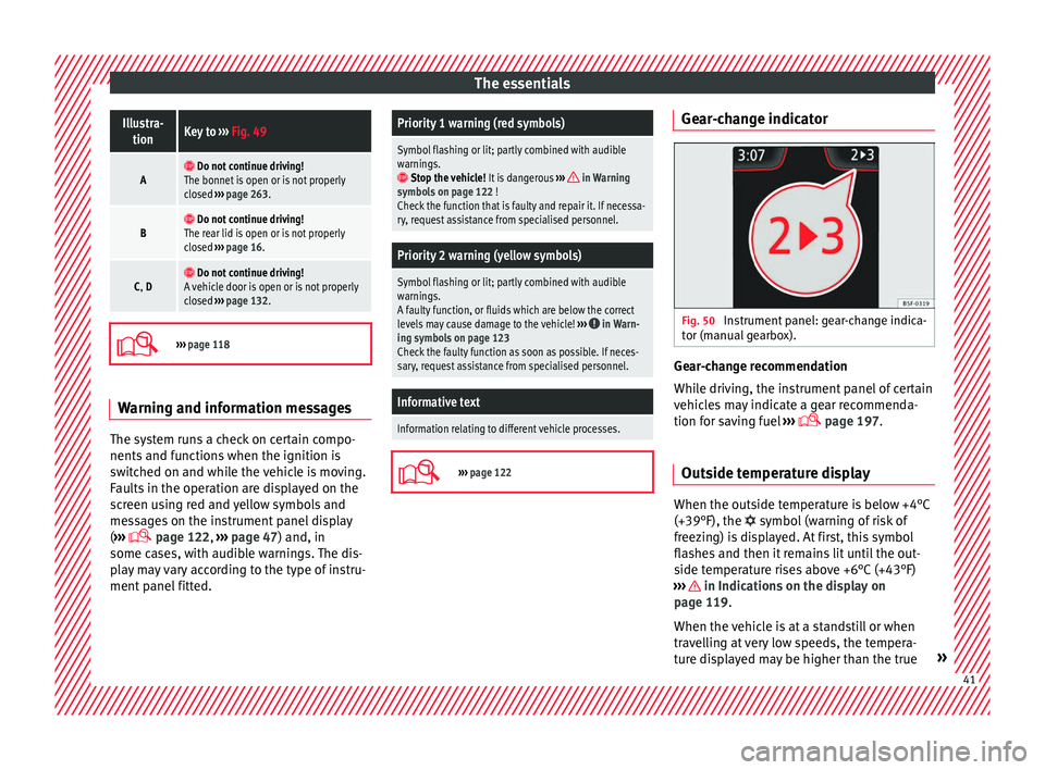
page 122 Gear-change indicator
Fig. 50
Instrument panel: gear-change indica-
t or (m
anual
gearbox). Gear-change recommendation
Whi
l
e driv
ing, the instrument panel of certain
vehicles may indicate a gear recommenda-
tion for saving fuel ›››
page 197.
Outside temperature display When the outside temperature is below +4°C
(+39°F), the
symbol
(w
arning of risk of
freezing) is displayed. At first, this symbol
flashes and then it remains lit until the out-
side temperature rises above +6°C (+43°F)
››› in Indications on the display on
p ag
e 119
.
When the vehicle is at a standstill or when
travelling at very low speeds, the tempera-
ture displayed may be higher than the true » 41
Page 44 of 312
The essentials
outside temperature as a result of the heat
pr oduc
ed b
y the engine.
The temperatures measured range from
-40°C to +50°C (-40°F to +122°F).
Engine oil temperature display The engine reaches its operating temperature
when in normal
driv
ing conditions the oil
temperature is between 80°C (178°F) and
120°C (248°F). If the engine is required to
work hard and the outside temperature is
high, the engine oil temperature can in-
crease. This does not present any problem as
long as the warning lamps ››› table on
page 48 or ››› table on page 48 do not
appear on the display.
Vehicles without multifunction steering
wheel
● Press the rocker switch ››
›
Fig. 47 2 until
the m ain menu ap
pe
ars. Enter into Driving
data . With the button 2 move to the oil
t emper
at
ure gauge.
Vehicles with multifunction steering wheel
● Enter the submenu Driving data and
turn the thumbwheel
until the oil tempera-
ture display appears. Additional consumers ●
Operation with the windscreen wiper lever*:
Pre s
s the rocker switch ››› Fig. 47 2 until the
main menu ap pe
ars. Enter into the section
Driving data . With the rocker switch,
move to the display Convenience con-
sumers .
● Operation with the multi-function steering
wheel*:
move with the buttons
or
to Driving data
and enter with
OK. Turn
the right thumbwheel until the Conven-
ience consumers display appears.
In addition, a scale will inform you of the cur-
rent sum of all the additional appliances.
Saving tips Tips on how to save fuel will be displayed in
c
ondition
s
that increase fuel consumption.
Follow them to reduce consumption. The indi-
cations appear automatically only with the ef-
ficiency programme. After a time, the tips will
disappear automatically.
If you wish to hide a saving tip immediately
after it appears, press any button on the
windscreen wiper lever*/multifunction steer-
ing wheel*. Note
● If y
ou hide a saving tip, it will reappear af-
ter you switch the ignition on again.
● The saving tips do not appear in all situa-
tions, but
rather with a large separation of
time. Speed warning device
The speed warning device warns the driver
when they h
av
e exceeded the pre-set speed
limit by 3 km/h (2 mph). An audible warning
signal sounds, and the warning lamp and
the driver message Speed limit excee-
ded! will be displayed simultaneously on the
instrument panel. The warning lamp
switches off when reducing speed below the
stored maximum limit.
Speed warning programming is recommen-
ded if you wish to be reminded of a maxi-
mum speed, such as when travelling in a
country with different speed limits or for a
maximum speed for winter tyres.
Setting speed limit warning
You can use the radio or the Easy Connect* to
set, alter or cancel the speed limit warning.
● Vehicles with radio : pres
s the SETUP button
> c ontr
o
l button Driver Assistant >
Speed warning .42
Page 45 of 312
The essentials
● Vehicle
s
with Easy Connect : Press the button and the function button SETTINGS >
Driver assistance > ACC > Dis-
tance .
The w arnin
g limit
can be set from 30 to
210 km/h (18 to 150 mph) ›››
page 209.
The adjustment is made at 10 km/h (6 mph)
intervals. Note
● Ple a
se bear in mind that, even with the
speed warning function, it is still important
to keep an eye on the vehicle speed with the
speedometer and to observe the legal speed
limits.
● The speed limit warning function in the ver-
sion for some c
ountries warns you at a speed
of 120 km/h (75 mph). This is a factory-set
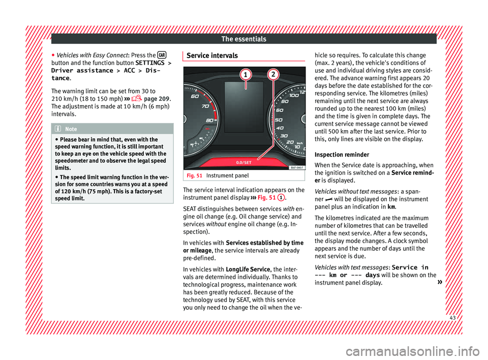
speed limit. Service intervals
Fig. 51
Instrument panel The service interval indication appears on the
in
s
trument
panel display ››› Fig. 51 1 .
S EA
T di
stinguishes between services with en-
gine oil change (e.g. Oil change service) and
services without engine oil change (e.g. In-
spection).
In vehicles with Services established by time
or mileage, the service intervals are already
pre-defined.
In vehicles with LongLife Service , the inter-
vals are determined individually. Thanks to
technological progress, maintenance work
has been greatly reduced. Because of the
technology used by SEAT, with this service
you only need to change the oil when the ve- hicle so requires. To calculate this change
(max. 2 y
ears), the vehicle's conditions of
use and individual driving styles are consid-
ered. The advance warning first appears 20
days before the date established for the cor-
responding service. The kilometres (miles)
remaining until the next service are always
rounded up to the nearest 100 km (miles)
and the time is given in complete days. The
current service message cannot be viewed
until 500 km after the last service. Prior to
this, only lines are visible on the display.
Inspection reminder
When the Service date is approaching, when
the ignition is switched on a Service remind-
er is displayed.
Vehicles without text messages : a span-
ner will be displayed on the instrument
panel plus an indication in km.
The kilometres indicated are the maximum
number of kilometres that can be travelled
until the next service. After a few seconds,
the display mode changes. A clock symbol
appears and the number of days until the
next service is due.
Vehicles with text messages : Service in
--- km or --- days will be shown on the
instrument panel display. » 43
Page 46 of 312
The essentials
Service due
When the ser v
ic
e date is due, an audible
warning is given when the ignition is switch-
ed on and the spanner displayed on the
screen flashes for a few seconds .
Vehicles with text messages : Service now
will be shown on the instrument panel dis-
play.
Reading a service notification
With the ignition switched on, the engine off
and the vehicle at a standstill, the current
service notification can be read:
Press and hold the button 0.0/SET for more
th an 5 sec
ond
s to consult the service mes-
sage 2 .
When the ser v
ic
e date has passed , a minus
sign is displayed in front of the number of kil-
ometres or days. Vehicles with text messages
: the fol
lowing
message is displayed: Service --- km
(miles) or --- days ago .
Resetting service interval display
If the service was not carried out by a SEAT
dealership, the display can be reset as fol-
lows: ● Switch off the ignition, press and hold the
button 0.0/S
ET
2 .
● Switch ignition back on.
● Release the button 0.0/S
ET and press it
ag ain f
or the ne
xt 20 seconds. Note
● The serv ic
e message disappears after a few
seconds, when the engine is started or when OK/RESET is pressed on the windscreen wiper
lev er
, or OK on the multifunction steering
wheel.
● In v
ehicles with the LongLife system in
which the batt
ery has been disconnected for
a long period of time, it is not possible to cal-
culate the date of the next service. Therefore the service interval display may not be cor-
rect
. In thi
s case, bear in mind the maximum
service intervals permitted in the ››› Booklet
Maintenance Programme.
● If you reset the display manually, the next
servic
e interval will be indicated as in vehi-
cles with fixed service intervals. For this rea-
son we recommend that the service interval
display be reset by a SEAT authorised Dealer. 44
Page 51 of 312
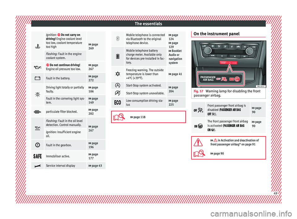
The essentials
Ignition: Do not carry on
driving! Engine coolant level
too low, coolant temperature
too high
››› page
269
Flashing: Fault in the engine
coolant system.
Do not continue driving!
Engine oil pressure too low.››› page
267
Fault in the battery.›››
page
272
Driving light totally or partially
faulty.›››
page
106
Fault in the cornering light sys-
tem.››› page
149
particulate filter blocked.›››
page
202
Flashing: Fault in the oil level
detection. Control manually.
›››
page
267
Ignition: Insufficient engine
oil.
Fault in the gearbox.›››
page
196
Immobiliser active.›››
page
177
Service interval display›››
page 43
Mobile telephone is connected
via Bluetooth to the original
telephone device.›››
page
124
››› page
129
››› Booklet
Audio or
navigation
system
Mobile telephone battery
charge meter. Available only
for devices pre-installed in fac-
tory.
Freezing warning. The outside
temperature is lower than
+4°C (+39°F).›››
page 41
Start-Stop system activated.›››
page
204
Start-Stop system unavailable.
Low consumption driving sta-
tus›››
page
225
›››
page 118 On the instrument panel
Fig. 57
Warning lamp for disabling the front
p a
s
senger airbag.
Front passenger front airbag is
disabled (
).
››› page
90
The front passenger front airbag
is activated (
).
››› page
90
››› in Activation and deactivation of
front passenger airbag* on page 91
››› page 90 49
Page 64 of 312
The essentials
Emergencies F u
se
s
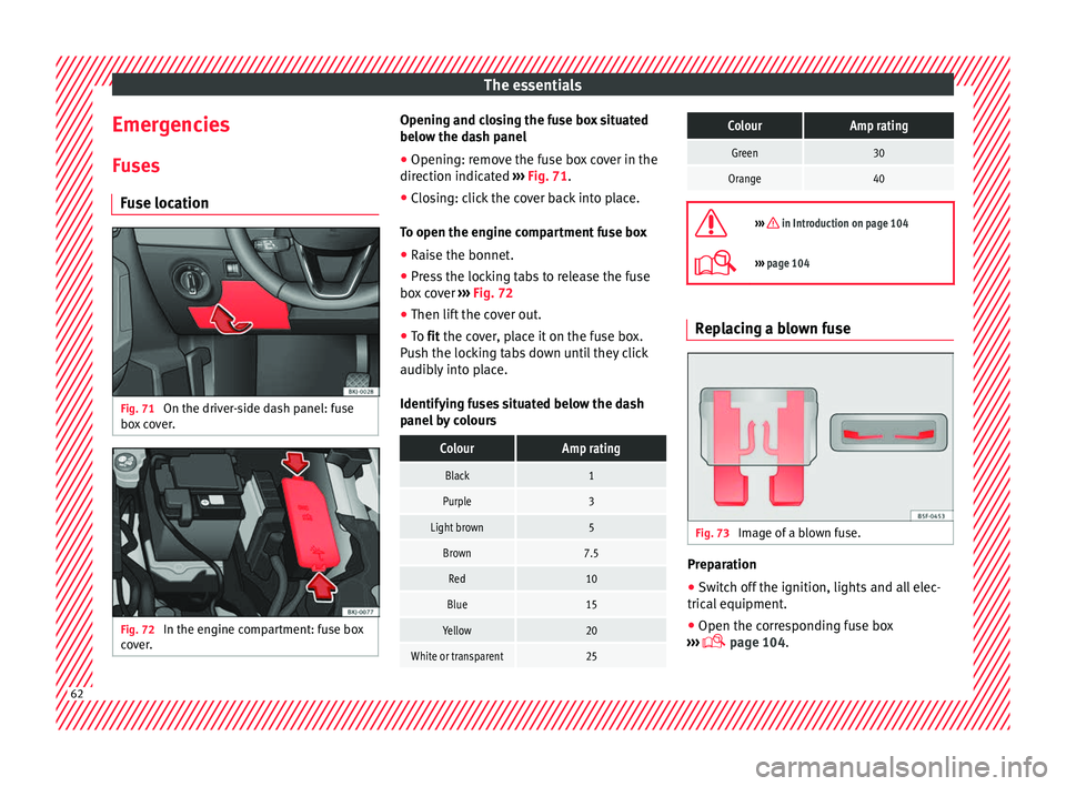
Fuse location Fig. 71
On the driver-side dash panel: fuse
bo x
c
over. Fig. 72
In the engine compartment: fuse box
c o
v
er. Opening and closing the fuse box situated
belo
w the d a
sh panel
● Opening: remove the fuse box cover in the
direction indicat
ed ››› Fig. 71.
● Closing: click the cover back into place.
To open the engine c
ompartment fuse box
● Raise the bonnet.
● Press the locking tabs to release the fuse
box c
over ››› Fig. 72
● Then lift the cover out.
● To fit the cover, place it on the fuse box.
Pu
sh the locking tabs down until they click
audibly into place.
Identifying fuses situated below the dash
panel by colours
ColourAmp rating
Black1
Purple3
Light brown5
Brown7.5
Red10
Blue15
Yellow20
White or transparent25
ColourAmp rating
Green30
Orange40
››› in Introduction on page 104
›››
page 104 Replacing a blown fuse
Fig. 73
Image of a blown fuse. Preparation
●
Switch off the ignition, lights and all elec-
tric al
equipment
.
● Open the corresponding fuse box
›››
page 104.62
Page 73 of 312
The essentials
Attach the tow rope or the tow bar only to the
t o
wline anc
horages provided or a towing
bracket.
Notes for the driver of the towing vehicle
● The tow rope must be taut before you drive
off.
● Rel
ease the clutch very carefully when start-
ing the v
ehicle (manual gearbox), or acceler-
ate gently (automatic gearbox).
Driving style
Towing requires some experience, especially
when using a tow rope. Both drivers should
realise how difficult it is to tow a vehicle. In-
experienced drivers should not attempt to
tow.
Do not pull too hard with the towing vehicle
and take care to avoid jerking the tow rope.
When towing on an unpaved road, there is al-
ways a risk of overloading and damaging the
anchorage points.
The ignition of the vehicle being towed must
be switched on to prevent the steering wheel
from locking and also to allow the use of the
turn signals, horn, windscreen wipers and
washers.
Place the gear lever in neutral on vehicles
with a manual gearbox. With an automatic
gearbox, place the lever in N. The brake servo only works when the engine
is ru
nning. When not running, you must ap-
ply considerably more pressure to the brake
pedal.
As the power assisted steering does not work
if the engine is not running, you will need
more strength to steer than you normally
would.
››› in General information on page 100
››› page 100 Tow-starting
If the engine will not start, first try starting it
u
s
in
g the battery of another vehicle
››› page 71. You should only attempt to tow-
start a vehicle if charging the battery does
not work. This is done by leveraging wheel
movement.
When tow-starting a vehicle with a petrol en-
gine, do not tow it more than a short dis-
tance, otherwise unburned fuel can enter the
catalytic converter.
However, if your vehicle has to be tow-star-
ted:
● Engage 2 nd
or 3 rd
ge
ar.
● Keep the clutch pressed down. ●
Switc
h the ignition on.
● Once both vehicles are moving, release the
clutc
h.
● As soon as the engine starts, press the
clutc
h and move the gear lever into neutral.
This helps to prevent driving into the towing
vehicle.
››› in General information on page 100
››› page 100 How to jump start
Jump l e
a
ds The jump lead must have a sufficient wire
c
r
o
ss section.
If the engine fails to start because of a dis-
charged battery, the battery can be connec-
ted to the battery of another vehicle to start
the engine.
Jump leads
Jump leads must comply with standard DIN
72553 (see cable manufacturer's instruc-
tions). The wire cross section must be at least
25 mm 2
for petrol engines and at least
35 mm 2
for diesel engines. » 71
Page 74 of 312
The essentials
Note
● The v ehic
les must not touch each other,
otherwise electricity could flow as soon as
the positive terminals are connected.
● The discharged battery must be properly
connected t
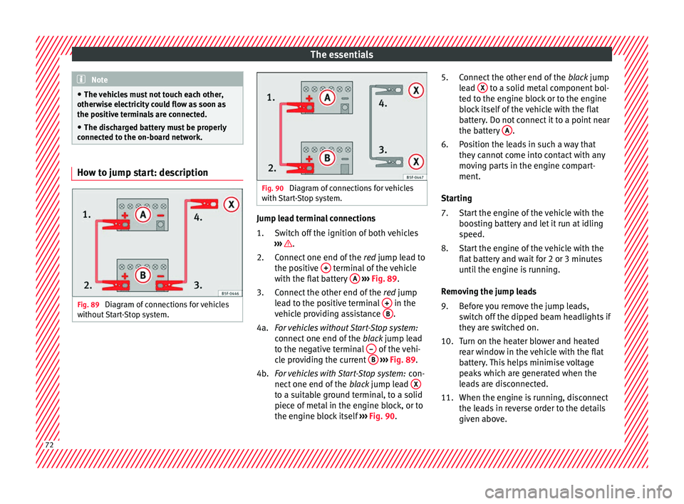
o the on-board network. How to jump start: description
Fig. 89
Diagram of connections for vehicles
w ithout
Start-Stop system. Fig. 90
Diagram of connections for vehicles
with St
art-Stop system. Jump lead terminal connections
Swit
c
h off the ignition of both vehicles
››› .
C onnect
one end of
the red jump lead to
the positive + terminal of the vehicle
w ith the fl
at
battery A
› ›
› Fig. 89 .
Connect the other end of the red jump
lead to the positive terminal + in the
v ehic
l
e providing assistance B .
F or
vehicles without Start-Stop system:
connect one end of the black jump lead
to the negative terminal – of the vehi-
c l
e pr
oviding the current B
› ›
› Fig. 89 .
For vehicles with Start-Stop system: con-
nect one end of the black jump lead X to a suitable ground terminal, to a solid
piec
e of
met
al in the engine block, or to
the engine block itself ››› Fig. 90.
1.
2.
3.
4a.
4b. Connect the other end of the
black
jump
lead X to a solid metal component bol-
t ed t
o the en
gine block or to the engine
block itself of the vehicle with the flat
battery. Do not connect it to a point near
the battery A .
P o
s
ition the leads in such a way that
they cannot come into contact with any
moving parts in the engine compart-
ment.
Starting Start the engine of the vehicle with the
boosting battery and let it run at idling
speed.
Start the engine of the vehicle with the
flat battery and wait for 2 or 3 minutes
until the engine is running.
Removing the jump leads Before you remove the jump leads,
switch off the dipped beam headlights if
they are switched on.
Turn on the heater blower and heated
rear window in the vehicle with the flat
battery. This helps minimise voltage
peaks which are generated when the
leads are disconnected.
When the engine is running, disconnect
the leads in reverse order to the details
given above.
5.
6.
7.
8.
9.
10.
11.
72
Page 76 of 312
The essentials
Do not change the windscreen wipers when
out of
the ser
vice position, as it could cause
paint to flake off the bonnet due to friction
with the windscreen wiper arm.
Service position (for changing wiper blades)
● Ensure that the wiper blades are not frozen.
● Turn the ignition on and off and then (with-
in appro
ximately 9 seconds) push the wind-
screen wiper lever down (short wipe). The
windscreen wipers will move to the service
position ››› Fig. 91.
Removing the wiper blade
● Lift the windscreen wiper arm.
● Press the securing tab down 1
› ›
› Fig. 92
.
● Extract the wiper blade from the wiper arm.
Fitting the wiper b
lade
● Insert the wiper blade onto the windscreen
wiper arm unti
l it clicks into place.
● Place the windscreen wiper arms to their in-
itial po
sition.
● Turn the ignition on, push the windscreen
wiper lev
er down (touch wipe) and then turn
the ignition off.
››› in Changing the windscreen and
rear window wiper blades on page 100
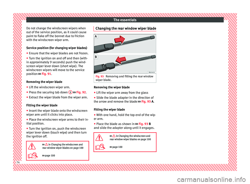
››› page 100 Changing the rear window wiper blade
Fig. 93
Removing and fitting the rear window
w iper b
l
ade. Removing the wiper blade
● Lift the wiper arm away from the glass
● Slide the blade adapter in the direction of
the arr o
w and r
emove the blade ››› Fig. 93 A.
Fitting the wiper blade
● With one hand, hold the top end of the wip-
er arm.
● Place the blade as shown in ›››
Fig. 93 B
and slide the adapter along until it engages.
››› in Changing the windscreen and
rear window wiper blades on page 100
››› page 100 74
Page 83 of 312
Seat belts
Seat belts
Wh y
w
ear a seat belt
Number of seats Your vehicle has
five se
ats, two in the front
and three in the rear. Each seat is equipped
with a three-point seat belt. WARNING
● Never tr an
sport more than the permitted
amount of people in your vehicle.
● Every vehicle occupant must properly fas-
ten and we
ar the seat belt belonging to his or
her seat. Children must be protected with an
appropriate child restraint system. Seat belt control lamp*
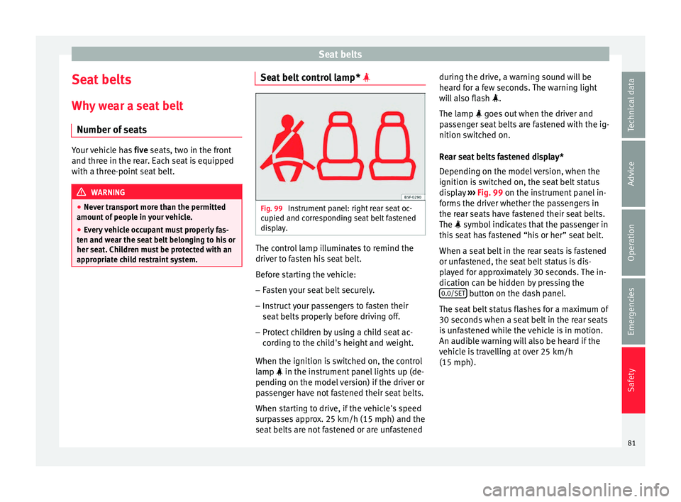
Fig. 99
Instrument panel: right rear seat oc-
c upied and c
orr
esponding seat belt fastened
display. The control lamp illuminates to remind the
driv
er t
o f
asten his seat belt.
Before starting the vehicle: – Fasten your seat belt securely.
– Instruct your passengers to fasten their
seat belts
properly before driving off.
– Protect children by using a child seat ac-
cordin
g to the child's height and weight.
When the ignition is switched on, the control
lamp in the instrument panel lights up (de-
pending on the model version) if the driver or
passenger have not fastened their seat belts.
When starting to drive, if the vehicle's speed
surpasses approx. 25 km/h (15 mph) and the
seat belts are not fastened or are unfastened during the drive, a warning sound will be
heard f
or a few seconds. The warning light
will also flash .
The lamp goes out when the driver and
passenger seat belts are fastened with the ig-
nition switched on.
Rear seat belts fastened display*
Depending on the model version, when the
ignition is switched on, the seat belt status
display ››› Fig. 99 on the instrument panel in-
forms the driver whether the passengers in
the rear seats have fastened their seat belts.
The symbol indicates that the passenger in
this seat has fastened “his or her” seat belt.
When a seat belt in the rear seats is fastened
or unfastened, the seat belt status is dis-
played for approximately 30 seconds. The in-
dication can be hidden by pressing the 0.0/SET button on the dash panel.
The se at
belt
status flashes for a maximum of
30 seconds when a seat belt in the rear seats
is unfastened while the vehicle is in motion.
An audible warning will also be heard if the
vehicle is travelling at over 25 km/h
(15 mph).
81
Technical data
Advice
Operation
Emergencies
Safety