fuel cap Seat Ibiza 5D 2014 User Guide
[x] Cancel search | Manufacturer: SEAT, Model Year: 2014, Model line: Ibiza 5D, Model: Seat Ibiza 5D 2014Pages: 240, PDF Size: 4.89 MB
Page 182 of 240
Advice
CAUTION
The prescribed tightening torque for wheel
bolts for steel and alloy wheels is 120 Nm. Winter service
Winter tyres In winter conditions winter tyres will consid-
erably improve the vehicle's handling. The
design of summer tyres (width, rubber com-
pound, tread pattern) gives less grip on ice
and snow.
Winter tyres must be inflated to a
pressure of
0.2 bar (2.9 psi/20 kPa) higher than the pres-
sures specified for summer tyres (see sticker
on fuel tank flap).
Winter tyres must be fitted on all four wheels.
Information on permitted winter tyre sizes
can be found in the vehicle's registration
documentation. Use only radial winter tyres.
All tyre sizes listed in the vehicle documenta-
tion also apply to winter tyres.
Winter tyres lose their effectiveness when the
tread is worn down to a depth of 4 mm.
The speed rating code ›››
page 178, New
tyres and wheels determines the following
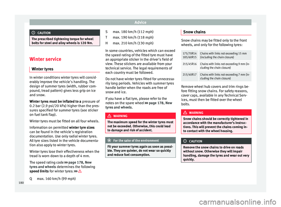
speed limits for winter tyres: ›› › max. 160 km/h (99 mph)
Q max. 180 km/h (112 mph)
max. 190 km/h (118 mph)
max. 210 km/h (130 mph)
In some countries, vehicles which can exceed
the speed rating of the fitted tyre must have
an appropriate sticker in the driver's field of
view. These stickers are available from your
technical service. The legal requirements of
each country must be followed.
Do not have winter tyres fitted for unnecessa-
rily long periods. Vehicles with summer tyres
handle better when the roads are free of
snow and ice.
If you have a flat tyre, please refer to the
notes on the spare wheel ››› page 178, New
tyres and wheels . WARNING
The maximum speed for the winter tyres must
not be exceeded. Otherwise, this could lead
to damage and risk of accident. For the sake of the environment
Fit your summer tyres again as soon as possi-
ble. They are quieter, do not wear so quickly
and reduce fuel consumption. S
T
H
Snow chains Snow chains may be fitted only to the front
wheels, and only for the following tyres:
175/70R14
185/60R15Chains with links not exceeding 15 mm
(including the chain closure)
215/45R16Chains with links not exceeding 9 mm (in-
cluding the chain closure)
215/40R17Chains with links not exceeding 7 mm (in-
cluding the chain closure)
Remove wheel hub covers and trim rings be-
fore fitting snow chains. For safety reasons,
cover caps, available in any Technical Serv-
ices, must then be fitted over the wheel
bolts.
WARNING
Snow chains should be correctly tightened in
accordance with the manufacturer's instruc-
tions. This will prevent the chains coming in-
to contact with the wheel housing. CAUTION
Remove the snow chains to drive on roads
without snow. Otherwise they will impair
handling, damage the tyres and wear out very
quickly. 180
Page 191 of 240
Emergencies
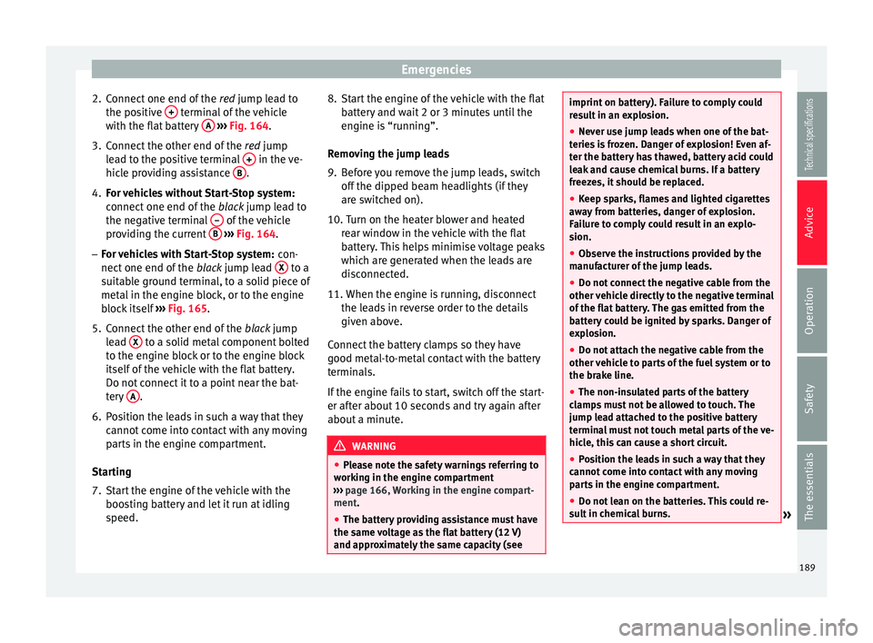
2. Connect one end of the red jump lead to
the po s
itive + terminal of the vehicle
with the flat battery A
››› Fig. 164 .
3. C
onnect the other end of the red
jump
lead to the positive terminal + in the ve-
hicle providing assistance B .
4. For vehicles without Start-Stop system:
connect one end of the black jump lead to
the negative terminal – of the vehicle
providing the current B
››› Fig. 164 .
– For
vehicles with Start-Stop system: con-
nect one end of the black jump lead X to a
suitable ground terminal, to a solid piece of
metal in the engine block, or to the engine
block itself ››› Fig. 165 .
5. C
onnect the other end of the black jump
lead X to a solid metal component bolted
to the engine block or to the engine block
itself of the vehicle with the flat battery.
Do not connect it to a point near the bat-
tery A .
6. Position the leads in such a way that they cannot come into contact with any moving
parts in the engine compartment.
Starting
7. Start the engine of the vehicle with the boosting battery and let it run at idling
speed. 8. Start the engine of the vehicle with the flat
battery and wait 2 or 3 minutes until the
engine is “running”.
Removing the jump leads
9. Before you remove the jump leads, switch off the dipped beam headlights (if they
are switched on).
10. Turn on the heater blower and heated rear window in the vehicle with the flat
battery. This helps minimise voltage peaks
which are generated when the leads are
disconnected.
11. When the engine is running, disconnect
the l e
ads in reverse order to the details
given above.
Connect the battery clamps so they have
good metal-to-metal contact with the battery
terminals.
If the engine fails to start, switch off the start-
er after about 10 seconds and try again after
about a minute. WARNING
● Please note the safety warnings referring to
working in the engine compartment
››› page 166, Working in the engine compart-
ment.
● The b att
ery providing assistance must have
the same voltage as the flat battery (12 V)
and approximately the same capacity (see imprint on battery). Failure to comply could
result in an explosion.
●
Never use jump leads when one of the bat-
teries is frozen. Danger of explosion! Even af-
ter the battery has thawed, battery acid could
leak and cause chemical burns. If a battery
freezes, it should be replaced.
● Keep sparks, flames and lighted cigarettes
away from batteries, danger of explosion.
Failure to comply could result in an explo-
sion.
● Observe the instructions provided by the
manufacturer of the jump leads.
● Do not connect the negative cable from the
other vehicle directly to the negative terminal
of the flat battery. The gas emitted from the
battery could be ignited by sparks. Danger of
explosion.
● Do not attach the negative cable from the
other vehicle to parts of the fuel system or to
the brake line.
● The non-insulated parts of the battery
clamps must not be allowed to touch. The
jump lead attached to the positive battery
terminal must not touch metal parts of the ve-
hicle, this can cause a short circuit.
● Position the leads in such a way that they
cannot come into contact with any moving
parts in the engine compartment.
● Do not lean on the batteries. This could re-
sult in chemical burns. » 189
Technical specifications
Advice
Operation
Safety
The essentials
Page 211 of 240
Technical features
Vehicles for certain export countries do not
have an identification plate.
Identification plate
The identification plate is located on the right
rib inside the engine compartment.
Vehicle data
The data sticker is placed on the inside of the
spare wheel well, in the boot and on the rear
cover of the Maintenance Programme.
The following information is provided on the
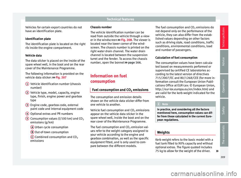
vehicle data sticker: ››› Fig. 207
Vehicle identification number (chassis
number)
Vehicle type, model, capacity, engine
type, finish, engine power and gearbox
type
Engine code, gearbox code, external
paint code and internal equipment code
Optional extras and PR numbers
Consumption values (l/100 km) and CO 2
emissions (g/km)
A Urban cycle consumption
B Out-of-town consumption
C Combined consumption and CO
2
emissions
1 2
3
4
5 Chassis number
The vehicle identification number can be
read from outside the vehicle through a view-
er in the windscreen
››› Fig. 208 . The viewer is
loc at
ed near the lower corner of the wind-
screen. The chassis number is printed on the
right water drain channel. The water drain
channel is located between the suspension
turret and the fender. To access the chassis
number, open the bonnet ››› page 166.
Information on fuel
consumption Fuel consumption and CO 2 emissions The consumption and emission details
shown on the vehicle data sticker differ from
one vehicle to another.
Vehicle fuel consumption and CO
2 emissions
appear on the vehicle data sticker in the
spare wheel well, inside the boot and on the
rear cover of the Maintenance Programme.
The fuel consumption and CO 2 emission val-
ues refer to the weight category assigned to
your vehicle according to the engine and
gearbox combination, as well as the specific
equipment fitted, and is only used to com-
pare between the different models. The fuel consumption and CO
2 emissions do
not depend only on the performance of the
vehicle, they can also differ from the estab-
lished values depending on other factors
such as driving style, road conditions, traffic
conditions, environmental conditions, load
and number of passengers.
Calculation of fuel consumption
The consumption values have been calcula-
ted based on measurements performed or
supervised by certified CE laboratories ac-
cording to the latest version of directives
715/2007/EC and 80/1268/CEE (for more in-
formation consult the European Union Publi-
cations Office at EUR-Lex: © European Union,
http://eur-lex.europa.eu/en/index.htm) and
are valid for the kerb weight indicated for the
vehicle. Note
In practice, and considering all the factors
mentioned here, consumption values can dif-
fer from those calculated in the current Euro-
pean regulations. Weights
Kerb weight refers to the basic model with a
fuel tank filled to 90% capacity and without
optional extras. The figure quoted includes
75 kg to allow for the weight of the driver.
»
209
Technical specifications
Advice
Operation
Safety
The essentials
Page 229 of 240

Technical features
CapacitiesCapacities
Fuel tank 45 litres. Reserve 7 li-
tres.
Windscreen washer fluid
container with headlight
washer 2 l/ 4.5 l
Tyre pressure
Summer tyres:
Correct tyre pressure can be seen on the sticker on the
inside of the fuel tank flap.
Winter tyres:
The pressure of these tyres is 0.2 bar higher than that of
summer tyres (2.9 psi / 20 kPa). 227
Technical specifications
Advice
Operation
Safety
The essentials
Page 236 of 240
Index
Remote control key Buttons . . . . . . . . . . . . . . . . . . . . . . . . . . . . . . . . 83
Synchronising . . . . . . . . . . . . . . . . . . . . . . . . . . . 84
Removing and fitting the wheel . . . . . . . . . . . . . 185
Replacement keys . . . . . . . . . . . . . . . . . . . . . . . . . 82
Replacement of parts . . . . . . . . . . . . . . . . . . . . . . 155
Rev counter . . . . . . . . . . . . . . . . . . . . . . . . . . . . . . . 56
Roll-back function panoramic/tilting sunroof . . . . . . . . . . . . . . . . . 90
Windows . . . . . . . . . . . . . . . . . . . . . . . . . . . . . . . 88
Roof aerial . . . . . . . . . . . . . . . . . . . . . . . . . . . . . . . 155
Roof carrier . . . . . . . . . . . . . . . . . . . . . . . . . . . . . . 111
Roof carrier system . . . . . . . . . . . . . . . . . . . . . . . . 111
Rubber seals . . . . . . . . . . . . . . . . . . . . . . . . . . . . . 160
Running in Brake pads . . . . . . . . . . . . . . . . . . . . . . . . . . . . 134
Engine . . . . . . . . . . . . . . . . . . . . . . . . . . . . . . . . 134
Tyres . . . . . . . . . . . . . . . . . . . . . . . . . . . . . . . . . 134
Running in tyres . . . . . . . . . . . . . . . . . . . . . . . . . . 134
S Safe . . . . . . . . . . . . . . . . . . . . . . . . . . . . . . . . . . . . . 79
Safe driving . . . . . . . . . . . . . . . . . . . . . . . . . . . . . . 29
Safe Security system . . . . . . . . . . . . . . . . . . . . . . . 79
Safety . . . . . . . . . . . . . . . . . . . . . . . . . . . . . . . . . . . 29 child safety . . . . . . . . . . . . . . . . . . . . . . . . . . . . . 46
child seats . . . . . . . . . . . . . . . . . . . . . . . . . . . . . . 46
Safety equipment . . . . . . . . . . . . . . . . . . . . . . . . . . 29
Safety information Front passenger airbag deactivation . . . . . . . . 46
Safety instructions Coolant temperature . . . . . . . . . . . . . . . . . . . . . 63
front airbags . . . . . . . . . . . . . . . . . . . . . . . . . . . . 43
side airbags . . . . . . . . . . . . . . . . . . . . . . . . . . . . 44
Safety notes Seat belt tensioners . . . . . . . . . . . . . . . . . . . . . . 39
Using seat belts . . . . . . . . . . . . . . . . . . . . . . . . . 36 Seals . . . . . . . . . . . . . . . . . . . . . . . . . . . . . . . . . . . 160
Seat belt
Adjusting . . . . . . . . . . . . . . . . . . . . . . . . . . . . . . . 12
Seat belt cleaning . . . . . . . . . . . . . . . . . . . . . . . . 163
Seat belt control lamp . . . . . . . . . . . . . . . . . . . . . . 35
Seat belt position for pregnant women . . . . . . . . . . . . . . . . . . . . . . 38
Seat belts . . . . . . . . . . . . . . . . . . . . . . . . . . . . . . 38
Seat belt protection . . . . . . . . . . . . . . . . . . . . . . . . 35
Seat belt release . . . . . . . . . . . . . . . . . . . . . . . . . . 38
Seat belts . . . . . . . . . . . . . . . . . . . . . . . . . . . . . . . . 34 Adjustment . . . . . . . . . . . . . . . . . . . . . . . . . . . . . 37
control lamp . . . . . . . . . . . . . . . . . . . . . . . . . . . . 35
Safety notes . . . . . . . . . . . . . . . . . . . . . . . . . . . . 36
unfastened . . . . . . . . . . . . . . . . . . . . . . . . . . . . . 36
Seat belt tensioner control lamp . . . . . . . . . . . . . . . . . . . . . . . . . . . . 42
Seat heating . . . . . . . . . . . . . . . . . . . . . . . . . . . . . 102
Selecting a gear . . . . . . . . . . . . . . . . . . . . . . . . . . 128
Selective opening . . . . . . . . . . . . . . . . . . . . . . . . . 80
Semiautomatic air conditioning controls . . . . . . . . . . . . . . . . . . . . . . . . . . . . . . . 118
Service interval display . . . . . . . . . . . . . . . . . . . . . 67
Side airbags . . . . . . . . . . . . . . . . . . . . . . . . . . . . . . 43 safety instructions . . . . . . . . . . . . . . . . . . . . . . . 44
Single headlight bulbs . . . . . . . . . . . . . . . . . . . . 198
Sitting position driver . . . . . . . . . . . . . . . . . . . . . . . . . . . . . . . . . . 30
Sitting position, occupants . . . . . . . . . . . . . . . . . . 30
Snow chains . . . . . . . . . . . . . . . . . . . . . . . . 180, 210
Soot accumulation in the diesel engine particu- late filter
control lamp . . . . . . . . . . . . . . . . . . . . . . . . . . . . 59
Spanner symbol . . . . . . . . . . . . . . . . . . . . . . . . . . . 67
Spare parts . . . . . . . . . . . . . . . . . . . . . . . . . . . . . . 155
Spare wheel . . . . . . . . . . . . . . . . . . . . . . . . . . . . . 182
Speedometer . . . . . . . . . . . . . . . . . . . . . . . . . . . . . 57 Speed selector lever lock
control lamp . . . . . . . . . . . . . . . . . . . . . . . . . . . . 62
Start-Stop Activating and deactivating . . . . . . . . . . . . . . . 143
functioning . . . . . . . . . . . . . . . . . . . . . . . . . . . . 142
Starting petrol engines . . . . . . . . . . . . . . . 124, 125
Starting the engine . . . . . . . . . . . . . . . . . . 124, 125 after the fuel tank has been run dry . . . . . . . . 125
Starting the vehicle . . . . . . . . . . . . . . . . . . . . . . . . 13
Steam jets . . . . . . . . . . . . . . . . . . . . . . . . . . . . . . . 158
Steering . . . . . . . . . . . . . . . . . . . . . . . . . . . . . . . . . 31 steering lock . . . . . . . . . . . . . . . . . . . . . . . . . . . 123
Steering wheel . . . . . . . . . . . . . . . . . . . . . . . . . . . . 13
Steering wheel height adjustment . . . . . . . . . . . . 31
Storage compartment . . . . . . . . . . . . . . . . . . . . . 110 Front passenger side . . . . . . . . . . . . . . . . . . . . 104
right front seat . . . . . . . . . . . . . . . . . . . . . . . . . 105
Sunroof . . . . . . . . . . . . . . . . . . . . . . . . . . . . . . . . . . 10
Sun visor Sliding/tilting sunroof . . . . . . . . . . . . . . . . . . . . 89
Sun visors . . . . . . . . . . . . . . . . . . . . . . . . . . . . . . . . 97
Switch Hazard warning lights . . . . . . . . . . . . . . . . . . . . 95
Heated rear window . . . . . . . . . . . . . . . . . . . . . . 96
Light switch . . . . . . . . . . . . . . . . . . . . . . . . . . . . . 90
Switches Electric windows . . . . . . . . . . . . . . . . . . . . . . . . . 87
Switching off the engine . . . . . . . . . . . . . . . . . . . 125
T
Tail lights . . . . . . . . . . . . . . . . . . . . . . . . . . . . . . . 203
Tank Fuel level . . . . . . . . . . . . . . . . . . . . . . . . . . . . . . . 64
Reserve indicator . . . . . . . . . . . . . . . . . . . . . . . . 64
Tank capacity . . . . . . . . . . . . . . . . . . . . . . . . . . . 64
Technical modifications . . . . . . . . . . . . . . . . . . . . 155
The PND (portable navigation device) . . . . . . . . . 69
234