sensor Seat Ibiza 5D 2014 User Guide
[x] Cancel search | Manufacturer: SEAT, Model Year: 2014, Model line: Ibiza 5D, Model: Seat Ibiza 5D 2014Pages: 240, PDF Size: 4.89 MB
Page 100 of 240
Operation
again, you have to turn the ignition off and
then on again.
● Do not put stickers on the windscreen in
front of the rain sensor*. This may cause sen-
sor disruption or faults. Rear window wiper
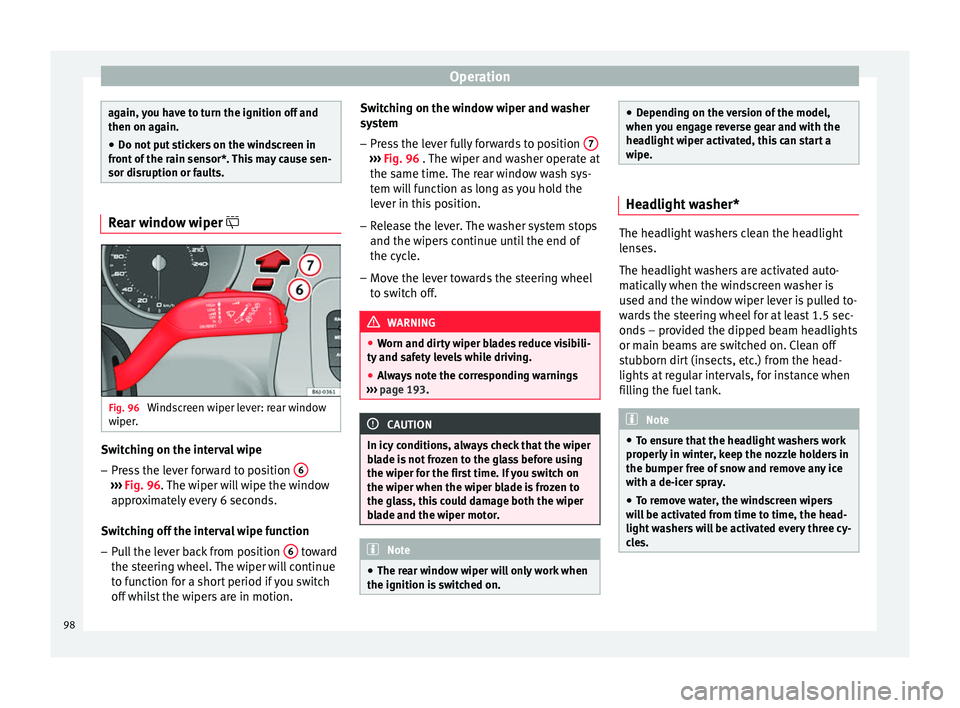
Fig. 96
Windscreen wiper lever: rear window
wiper. Switching on the interval wipe
– Press the lever forward to position 6›››
Fig. 96 . The wiper will wipe the window
ap pr
oximately every 6 seconds.
Switching off the interval wipe function
– Pull the lever back from position 6 toward
the steering wheel. The wiper will continue
to function for a short period if you switch
off whilst the wipers are in motion. Switching on the window wiper and washer
system
– Press the lever fully forwards to position 7 ›››
Fig. 96 . The wiper and washer operate at
the s ame time.
The rear window wash sys-
tem will function as long as you hold the
lever in this position.
– Release the lever. The washer system stops
and the wipers continue until the end of
the cycle.
– Move the lever towards the steering wheel
to switch off. WARNING
● Worn and dirty wiper blades reduce visibili-
ty and safety levels while driving.
● Always note the corresponding warnings
››› page 193. CAUTION
In icy conditions, always check that the wiper
blade is not frozen to the glass before using
the wiper for the first time. If you switch on
the wiper when the wiper blade is frozen to
the glass, this could damage both the wiper
blade and the wiper motor. Note
● The rear window wiper will only work when
the ignition is switched on. ●
Depending on the version of the model,
when you engage reverse gear and with the
headlight wiper activated, this can start a
wipe. Headlight washer*
The headlight washers clean the headlight
lenses.
The headlight washers are activated auto-
matically when the windscreen washer is
used and the window wiper lever is pulled to-
wards the steering wheel for at least 1.5 sec-
onds – provided the dipped beam headlights
or main beams are switched on. Clean off
stubborn dirt (insects, etc.) from the head-
lights at regular intervals, for instance when
filling the fuel tank.
Note
● To ensure that the headlight washers work
properly in winter, keep the nozzle holders in
the bumper free of snow and remove any ice
with a de-icer spray.
● To remove water, the windscreen wipers
will be activated from time to time, the head-
light washers will be activated every three cy-
cles. 98
Page 101 of 240
Lights and visibility
Rear view mirrors Interior rear vision mirror It is dangerous to drive if you cannot see
clearly through the rear window.
Manual anti-dazzle function for interior rear
vision mirror
In the basic mirror position, the lever at the
bottom edge of the rear vision mirror should
be at the front. Pull the lever to the back to
select the anti-dazzle function.
Automatic anti-dazzle interior rear
vision mirror* Read the additional information carefully
››› page 13
Anti-dazzle function
The anti-dazzle function is activated every
time the ignition is switched on. The green
warning lamp lights up in the rear vision mir-
ror housing.
When the anti-dazzle function is enabled, the
interior rear vision mirror will darken auto-
matically according to the amount of light it
r ec
eives. The anti-dazzle function is cancel-
led if reverse gear is engaged. Note
● The automatic anti-dazzle function will only
work properly if the sun blind* for the rear
window is retracted and there are no other
objects preventing light from reaching the in-
terior rear vision mirror.
● If you have to stick any type of sticker on
the windscreen, do not do so in front of the
sensors. Doing so could prevent the anti-daz-
zle function from working well or even from
working at all. Folding in the exterior mirrors
The exterior mirrors of the vehicle may be fol-
ded in. For this, press the mirror housing to-
wards the vehicle.
Note
Before washing the vehicle with an automatic
car wash, fold in the exterior mirrors to avoid
damage. Electric exterior mirrors*
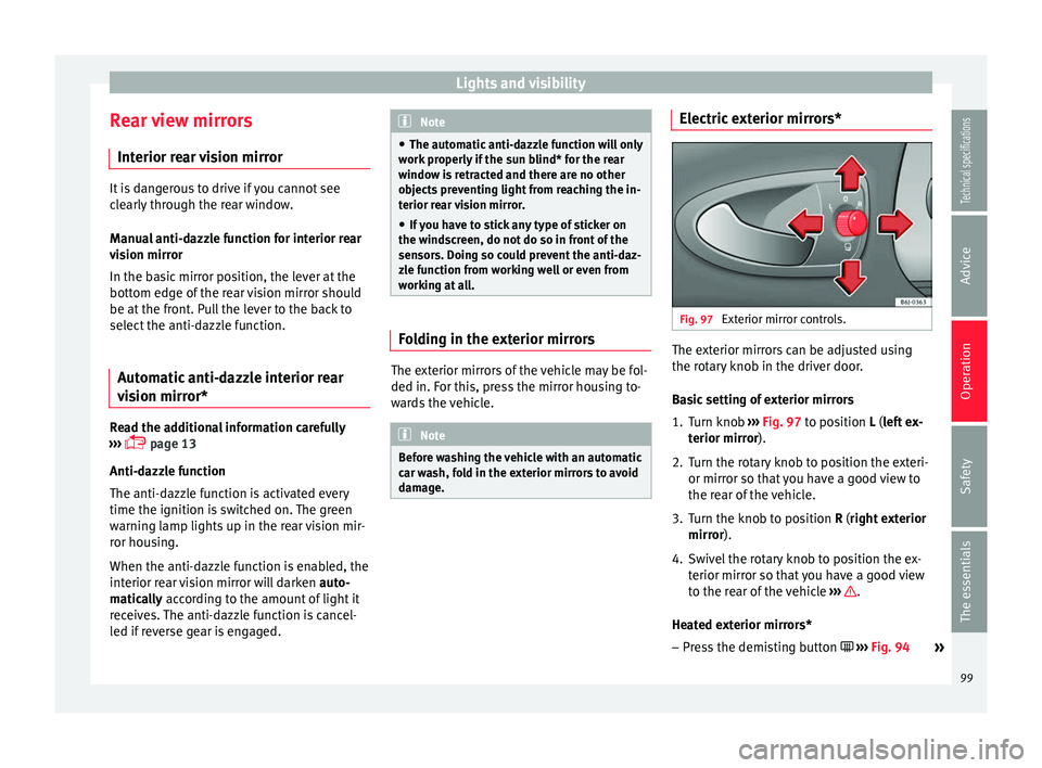
Fig. 97
Exterior mirror controls. The exterior mirrors can be adjusted using
the rotary knob in the driver door.
Basic setting of exterior mirrors
1. Turn knob
››› Fig. 97 to position L (left ex-
t erior mirr
or).
2. T
urn the rotary knob to position the exteri-
or mirror so that you have a good view to
the rear of the vehicle.
3. Turn the knob to position R (right exterior mirror
).
4. Swivel the rotary knob to position the ex- terior mirror so that you have a good view
to the rear of the vehicle ››› .
Heated exterior mirrors* – Press the demisting button ››› Fig. 94
»
99
Technical specifications
Advice
Operation
Safety
The essentials
Page 141 of 240
Driver assistance systems
Driver assistance systems
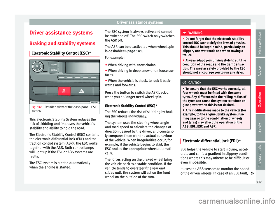
Braking and stability systems Electronic Stability Control (ESC)* Fig. 140
Detailed view of the dash panel: ESC
switch. This Electronic Stability System reduces the
risk of skidding and improves the vehicle's
stability and ability to hold the road.
The Electronic Stability Control (ESC) contains
the electronic differential lock (EDL) and the
traction control system (ASR). The ESC works
together with the ABS. Both control lamps
will light up if the ESC or ABS systems are
faulty.
The ESC system is started automatically
when the engine is started. The ESC system is always active and cannot
be switched off. The ESC switch only switches
the ASR off.
The ASR can be deactivated when wheel spin
is desirable
››› page 141 .
F or e
xample:
● When driving with snow chains.
● When driving in deep snow or on loose sur-
faces.
● When the vehicle is stuck, to rock it back-
wards and forwards.
Press the button to switch the ASR back on
when you no longer need wheel spin.
Electronic Stability Control (ESC)*
The ESC reduces the risk of skidding by brak-
ing the wheels individually.
The system uses the steering wheel angle
and road speed to calculate the changes of
direction desired by the driver, and constant-
ly compares them with the actual behaviour
of the vehicle. When irregularities occur, for
example, if the vehicle begins to skid, the
ESC brakes the appropriate wheel automati-
cally.
The forces acting on the braked wheel bring
the vehicle back to a stable condition. If the
vehicle tends to oversteer (the rear end
slides out), the system will act on the front
wheel on the outside of the turn. WARNING
● Do not forget that the electronic stability
control ESC cannot defy the laws of physics.
This should be kept in mind, particularly on
slippery and wet roads and when towing a
trailer.
● Always adapt your driving style to suit the
condition of the roads and the traffic situa-
tion. The greater safety provided by the ESC
should not encourage you to run any risks. CAUTION
● To ensure that the ESC works correctly, all
four wheels must be fitted with the same
tyres. Any differences in the rolling radius of
the tyres can cause the system to reduce en-
gine power when this is not desired.
● Any modifications made to the vehicle (for
example, to the engine, brake system, run-
ning gear or to the combination of wheels
and tyres) may affect the operation of the
ABS, EDL, ESC and ASR. Electronic differential lock (EDL)*
EDL helps the vehicle to start moving, accel-
erate and climb a gradient in slippery condi-
tions where this may otherwise be difficult or
even impossible.
It uses the ABS sensors to monitor the speed
of the driven wheels. In case of an EDL fault,
»
139Technical specifications
Advice
Operation
Safety
The essentials
Page 144 of 240
Operation
XDS* When taking a curve, the driveshaft differen-
tial mechanism allows the outer wheel to turn
at a higher speed than the inner wheel. In
this way, the wheel that is turning faster (out-
er wheel) receives less drive torque than the
inner wheel. This may mean that in certain
situations the torque delivered to the inner
wheel is too high, causing the wheels to
spin. On the other hand, the outer wheel is
receiving a lower drive torque than it could
transmit. This causes an overall loss of lateral
grip on the front axle, resulting in understeer
or “lengthening” of the trajectory.
The XDS system can detect and correct this
effect via the sensors and signals of the ESC.
Via the ESC, the XDS will brake the inside
wheel and counter the excess driving torque
of that wheel. This means that the driver's
desired trajectory is much more precise,
The XDS system works in combination with
the ESC and is always active, even when ASR
traction control is disconnected.
Brake servo The brake servo increases the pressure you
apply to the brake pedal. It works
only when
the engine is running . If the brake servo is not functioning, e.g. due
to a malfunction, or if the vehicle is being
towed, you will have to press the brake pedal
considerably harder to make up for the lack
of servo assistance.
WARNING
The braking distance can also be affected by
external factors.
● Never let the vehicle coast with the engine
switched off. Failure to follow this instruction
could result in an accident. The braking dis-
tance is increased considerably when the
brake servo is not active.
● If the brake servo is not working, for exam-
ple when the vehicle is being towed, you will
have to press the brake pedal considerably
harder than normal. Start-Stop System*
Description and operation The Start-Stop function stops the engine
when the vehicle is stopped and starts it au-
tomatically when required.
– When the vehicle is stopped, put it in neu-
tral and release the clutch pedal. The en-
gine will stop.
– When the clutch pedal is pressed, the en-
gine starts again. –
The instrument panel display shows infor-
mation about the status of the Start-Stop
function ››› Fig. 142 .
St ar
t-Stop function conditions
● The driver seat belt must be buckled.
● The bonnet must be closed.
● The engine must be at operating tempera-
ture.
● The steering wheel must be straight.
● The vehicle must be on flat ground.
● The vehicle must not be in reverse.
● A trailer must not be connected.
● The temperature of the interior must be
within the comfort limits ( A/C button should
be selected).
● The windscreen de-mist function must be
off.
● If in an increase in airflow is not requested.
● The t emper
ature must not be set to HI or
LO.
● The driver door must be closed.
● The diesel particulate filter must not be in
regeneration mode, for diesel engines.
● The battery charge must not be low for the
next start.
● Battery temperature must be between -1 °C
(+30 °F) and +55 °C (+131 °F).
142
Page 148 of 240
Operation
Parking and manoeuvring with the
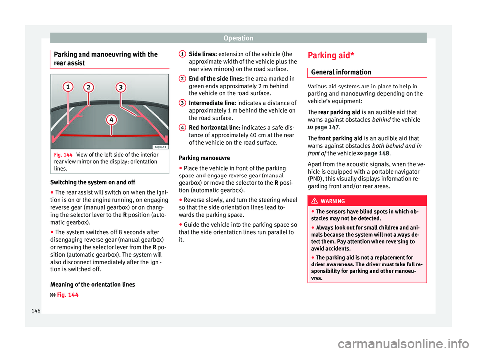
rear assist Fig. 144
View of the left side of the interior
rear view mirror on the display: orientation
lines. Switching the system on and off
● The rear assist will switch on when the igni-
tion is on or the engine running, on engaging
reverse gear (manual gearbox) or on chang-
ing the selector lever to the R position (auto-
m atic
gearbox).
● The system switches off 8 seconds after
disengaging reverse gear (manual gearbox)
or removing the selector lever from the R po-
sition (automatic gearbox). The system will
also disconnect immediately after the igni-
tion is switched off.
Meaning of the orientation lines
››› Fig. 144 Side lines: extension of the vehicle (the
approximate width of the vehicle plus the
rear view mirrors) on the road surface.
End of the side lines:
the area marked in
green ends approximately 2 m behind
the vehicle on the road surface.
Intermediate line: indicates a distance of
approximately 1 m behind the vehicle on
the road surface.
Red horizontal line: indicates a safe dis-
tance of approximately 40 cm at the rear
of the vehicle on the road surface.
Parking manoeuvre
● Place the vehicle in front of the parking
space and engage reverse gear (manual
gearbox) or move the selector to the R posi-
tion (automatic gearbox).
● Reverse slowly, and turn the steering wheel
so that the side orientation lines lead to-
wards the parking space.
● Guide the vehicle into the parking space so
that the side orientation lines run parallel to
it. 1 2
3
4 Parking aid*
General information Various aid systems are in place to help in
parking and manoeuvring depending on the
vehicle’s equipment:
The rear parking aid
is an audible aid that
w
arns against obstacles behind the vehicle
››› page 147.
The front parking aid i
s an audible aid that
warns against obstacles both behind and in
front of the vehicle ›››
page 148.
Apart from the acoustic signals, when the ve-
hicle is equipped with a portable navigator
(PND), this visually displays information re-
garding front and/or rear areas. WARNING
● The sensors have blind spots in which ob-
stacles may not be detected.
● Always look out for small children and ani-
mals because the system will not always de-
tect them. Pay attention when reversing to
avoid accidents.
● The parking aid is not a replacement for
driver awareness. The driver must take full re-
sponsibility for parking and other manoeu-
vres. 146
Page 149 of 240
Driver assistance systems
Rear parking aid The parking aid system will use an audible
warning to indicate of the approach of any
object towards the rear of the vehicle.
Description
The acoustic parking aid system will measure
the distance between the rear of the vehicle
and any possible obstacle using four ultra-
sonic sensors located on the rear bumper.
The measuring range of the sensors starts
approximately and depending on the nature
of the obstacle
at a distance of:
● side of the rear bumper: 0.6 m
● middle of the rear bumper: 1.6 m
Activation
The system is activated by engagement of
the reverse gear. A brief audible warning con-
firms the activation and correct function of
the system.
Reverse gear
The distance warning will begin as soon as
an obstacle is detected by the system. The
frequency of the bleeps emitted by the sys-
tem will increase rapidly as the vehicle ap-
proaches the obstacle. After a distance lower
than approximately 30 cm, a continuous sig-
nal sounds (stop signal). The driver should
not reverse any further. Models with a factory-fitted towing bracket:
when the vehicle is less than 0.35 m away
the warning tone will sound continuously.
The driver should then not reverse any fur-
ther.
The warning tone volume decreases by 30%
3 seconds after it the system is triggered
if
the detected obstacle stays at a constant dis-
tance from the vehicle .
Provided that it is not in continuous mode,
the tone on the parking aid system stops
when it detects a wall parallel to the vehicle.
Trailer towing
For vehicles factory-fitted with a towing bar,
the parking aid system will not be activated
by the engagement of the reverse gear when
pulling a trailer, as the trailer's electric con-
nector will be plugged into the vehicle.
Possible faults
If a continuous beep sounds for some sec-
onds when the reverse gear is engaged, this
indicates that there is a fault in the parking
aid system. If the fault continues until the ig-
nition is turned off, the audible warning of
the fault will not be emitted every time the
system is reactivated (by engaging the re-
verse gear). Thus, the system ready indica-
tion will not sound either. Have the fault re-
paired by technical services as soon as possi-
ble. If there is no ready signal or no acoustic
warning signal, then the parking aid loud-
speaker is faulty and may not warn of obsta-
cles. To ensure that the system works proper-
ly, the sensors must be kept clean and free of
ice and snow.
CAUTION
● Please note that low obstacles detected by
the system may no longer be registered by
the sensors as the car moves closer, so the
system will not give any further warning. Cer-
tain kinds of obstacles, such as wire fences,
chains, thin posts or trailer draw bars, high
kerbs or painted railings, etc., may not al-
ways be detected by the system, so there is a
risk of damaging the vehicle in such cases.
● In some case, obstacles with edges and
bumps may not be detected immediately by
the system due to their geometry. Take spe-
cial care with this type of obstacle (corners,
rectangular objects, etc.), as they can cause
damage to the vehicle.
● Be especially careful when manoeuvring in-
to a corner between two perpendicular walls.
Pay special attention to the side distance
from the wall using the mirrors.
● The parking aid system does not replace
use of the mirrors for manoeuvres.
● External ultra-sonic sources (pneumatic
drills, construction machinery, other vehicles
with PDC) may interfere with the operation of
the system. » 147Technical specifications
Advice
Operation
Safety
The essentials
Page 150 of 240
Operation
●
Periodic cleaning of the sensors, take care
not to damage or scratch them. When clean-
ing with high pressure washers or steam
cleaners, the sensors should be sprayed for
only a very short period and from a distance
of more than 10 cm.
● If the licence plate (especially the front
one) is bent in such a way that it noticeably
juts out from the bumper, false alarms may
sound for the area in front of the vehicle. Rear parking aid with navigator view
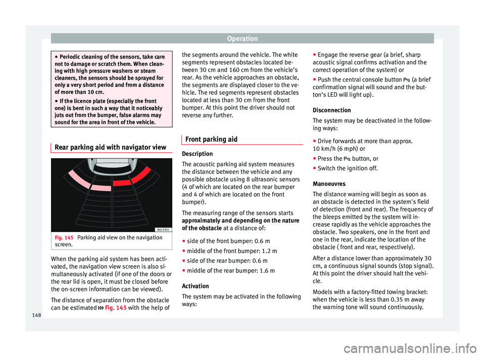
Fig. 145
Parking aid view on the navigation
screen. When the parking aid system has been acti-
vated, the navigation view screen is also si-
multaneously activated (if one of the doors or
the rear lid is open, it must be closed before
the on-screen information can be viewed).
The distance of separation from the obstacle
can be estimated
››› Fig. 145 with the help of the segments around the vehicle. The white
segments represent obstacles located be-
tween 30 cm and 160 cm from the vehicle’s
rear. As the vehicle approaches an obstacle,
the segments are displayed closer to the ve-
hicle. The red segments represent obstacles
located at less than 30 cm from the front
bumper. At this point the driver should not
reverse any further.
Front parking aid Description
The acoustic parking aid system measures
the distance between the vehicle and any
possible obstacle using 8 ultrasonic sensors
(4 of which are located on the rear bumper
and 4 of which are located on the front
bumper).
The measuring range of the sensors starts
approximately and depending on the nature
of the obstacle
at a distance of:
● side of the front bumper: 0.6 m
● middle of the front bumper: 1.2 m
● side of the rear bumper: 0.6 m
● middle of the rear bumper: 1.6 m
Activation
The system may be activated in the following
ways: ●
Engage the reverse gear (a brief, sharp
acoustic signal confirms activation and the
correct operation of the system) or
● Push the central console button (a brief
confirmation signal will sound and the but-
ton’s LED will light up).
Disconnection
The system may be deactivated in the follow-
ing ways:
● Drive forwards at more than approx.
10 km/h (6 mph) or
● Press the button, or
● Switch the ignition off.
Manoeuvres
The distance warning will begin as soon as
an obstacle is detected in the system's field
of detection (front and rear). The frequency of
the bleeps emitted by the system will in-
crease rapidly as the vehicle approaches the
obstacle. Two speakers, one in the front and
one in the rear, indicate the location of the
obstacle ( front and rear, respectively).
After a distance lower than approximately 30
cm, a continuous signal sounds (stop signal).
At this point the driver should halt the vehi-
cle.
Models with a factory-fitted towing bracket:
when the vehicle is less than 0.35 m away
the warning tone will sound continuously.
148
Page 151 of 240
Driver assistance systems
The driver should then not reverse any fur-
ther.
The warning tone volume decreases by 30%
3 seconds after it is triggered if the detected
obstacle stays at a constant distance from
the vehicle.
Provided that it is not in continuous mode,
the tone on the parking aid system stops
when it detects a wall parallel to the vehicle.
Trailer towing
For vehicles factory-fitted with a towing bar,
the parking aid system will not be activated
by the engagement of the reverse gear when
pulling a trailer, as the trailer's electric con-
nector will be plugged into the vehicle.
Possible faults
If a continuous, sharp beep sounds for a few
seconds, there is a fault in the parking aid
system.
If the fault continues until the ignition is
turned off, the audible warning of the fault
will not be emitted every time the system is
reactivated (by engaging the reverse gear or
pressing the button). Thus, the system
ready indication will not sound either. Have
the fault repaired by technical services as
soon as possible.
If there is no ready signal or no acoustic
warning signal, then the parking aid loud- speaker is faulty and may not warn of obsta-
cles. To ensure that the system works proper-
ly, the sensors must be kept clean and free of
ice and snow.
CAUTION
● Please note that low obstacles detected by
the system may no longer be registered by
the sensors as the car moves closer, so the
system will not give any further warning. Cer-
tain kinds of obstacles, such as wire fences,
chains, thin posts or trailer draw bars, high
kerbs or painted railings, etc., may not al-
ways be detected by the system, so there is a
risk of damaging the vehicle in such cases.
● In some cases, obstacles with uniform
edges and bumps may not be detected imme-
diately by the system due to their geometry.
Take special care with this type of obstacle
(corners, rectangular objects, etc.), as they
can cause damage to the vehicle.
● Be especially careful when manoeuvring in-
to a corner between two perpendicular walls.
Pay special attention to the side distance
from the wall using the mirrors.
● The parking aid system does not replace
use of the mirrors for manoeuvres.
● External ultra-sonic sources (e.g. pneumat-
ic drills, construction machinery or other ve-
hicles equipped with PND) may interfere with
the operation of the system.
● Periodic cleaning of the sensors, take care
not to damage or scratch them. When clean-
ing with high pressure washers or steam cleaners, the sensors should be sprayed for
only a very short period and from a distance
of more than 10 cm.
●
If the licence plate (especially the front
one) is bent in such a way that it noticeably
juts out from the bumper, false alarms may
sound for the area in front of the vehicle. Front parking aid with navigator view
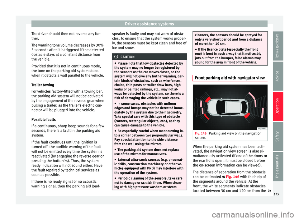
Fig. 146
Parking aid view on the navigation
screen. When the parking aid system has been acti-
vated, the navigation view screen is also si-
multaneously activated (if one of the doors or
the rear lid is open, it must be closed before
the on-screen information can be viewed).
The distance of separation from the obstacle
can be estimated
››› Fig. 146 with the help of
the segments around the vehicle. At the
front, the white segments indicate obstacles
located between 30 cm and 120 cm from the »
149Technical specifications
Advice
Operation
Safety
The essentials