engine Seat Ibiza 5D 2014 Owner's Guide
[x] Cancel search | Manufacturer: SEAT, Model Year: 2014, Model line: Ibiza 5D, Model: Seat Ibiza 5D 2014Pages: 240, PDF Size: 4.89 MB
Page 68 of 240
Operation
Km (miles) - Fuel range The fuel range is calculated using the figures
for tank content and current fuel consump-
tion. This shows how far the vehicle can trav-
el using the same conditions as a reference.
Ø l/100 km - Average fuel consumptionAfter turning on the ignition, average fuel
consumption will be shown after travelling
approximately 100 metres. Until then dashes
will appear in the display. The display will be
updated every 5 seconds while the vehicle is
in motion. The amount of fuel used will not
be shown.
l/100 km o l/h - Current fuel consumption
The display will show the current fuel con-
sumption in ltr/km whilst the vehicle is in
motion or in ltr/hour when the vehicle is at a
standstill with the engine running.
Using this display you can see how your driv-
ing style affects fuel consumption
››› page 134 .
Indic at
ed speed warning
When the required speed has been reached,
enter the “Speed warning” mode in the menu and press button
››› Fig. 74 A
RESET . The set
speed is memorised. If the indicated speed is
exceeded at any time, a warning message is
displayed on the screen and an audible warn-
ing sounds. 1)
This may be deactivated by pressing the RESET button. The speed may be altered us-
ing the rocker switch ››› Fig. 74 B in intervals
of 5 km/h within 5 seconds of the initial
memory value being stored.
Outside temperature display
The measurement margin ranges from -45 °C
(-49 °F) to +58 °C (+136 °F). At temperatures
lower than +4°C (+39 °F), an “ice crystal sym-
bol” is displayed and a “warning” is sounded
if the vehicle is moving at more than 10 km/h
(6 mph) (ice warning). This symbol will flash
for about 10 seconds and remains lit until
the outside temperature rises above +4°C
(+39°F), or if you are driving, the temperature
does not rise above +6°C (+43°F) if it was al-
ready lit.
The lighting of the ice crystal symbol is in-
tended to warn the driver of the risk of ice,
so that he/she proceeds with due care. WARNING
There could be black ice on the road surface
even if the “snowflake symbol” is not shown.
For this reason you should not rely exclusive-
ly on this display - Risk of accident! Note
When the vehicle is at a standstill or when
travelling at very low speeds, the tempera-
ture displayed may be higher than the true
outside temperature as a result of the heat
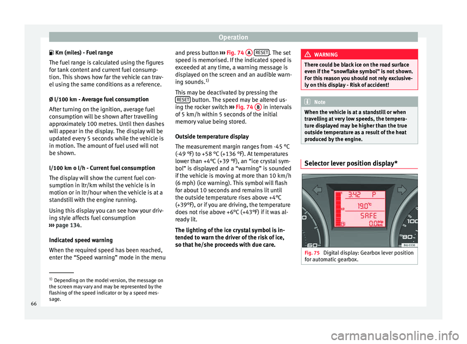
produced by the engine. Selector lever position display*
Fig. 75
Digital display: Gearbox lever position
for automatic gearbox. 1)
Depending on the model version, the message on
the screen may vary and may be represented by the
flashing of the speed indicator or by a speed mes-
sage.
66
Page 69 of 240
Dash panel
The position of the automatic selector lever
will be shown on the display ››› page 129.
Odometer The upper counter in the display registers the
total mileage covered by the vehicle.
The lower counter registers the short jour-
neys. The last digit indicates 100-metre sec-
tions. The trip recorder counter may be reset
by pressing the reset button
››› Fig. 70 5 .
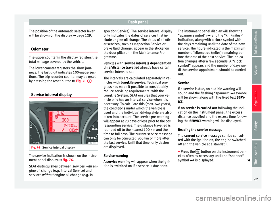
Service interval display Fig. 76
Service interval display The service indication is shown on the instru-
ment panel display
››› Fig. 76 .
S EA
T distinguishes between services with
en-
gine oil change (e.g. Interval Service) and
services without
engine oil change (e.g. In- spection Service). The service interval display
only indicates the dates of services that in-
clude engine oil change. The dates of all oth-
er services, such as Inspection Service or
brake fluid change, appear in the sticker on
the door pillar or in the Maintenance Pro-
gramme.
Vehicles with
service intervals dependent on
time/distance travelled already have certain
service intervals set.
The intervals are calculated separately in ve-
hicles with LongLife service. Technical pro-
gre
ss has made it possible to considerably
reduce servicing requirements. With the
LongLife System, SEAT ensures that your ve-
hicle only has an interval service when it is
necessary. To calculate this (max. two years),
the conditions under which the vehicle is
used and the individual driving style are also
taken into account. The service pre-warning
will appear at 20 days or less prior to the cor-
responding service. The distance travelled is
rounded off to the nearest 100 km and the
time to full days. The current service message
can only be consulted 500 km or more after
the last service. Until that time, only dashes
are displayed.
Service warning
A service warning will appear when the igni-
tion i
s switched on if a service is due soon. The instrument panel display will show the
“spanner symbol”
and the “km (miles)”
indication, along with a clock symbol with
the days remaining until the date of the next
service. The figure indicated is the maximum
number of kilometres (miles) remaining be-
fore the date of the next service. The indica-
tion changes after a few seconds. A “clock
symbol” appears and the number of days un-
til the service appointment should be carried
out.
Service
If a service is due, an audible warning will
sound and the flashing “spanner” symbol
will be shown along with the fixed text SERV-
ICE.
If no service is carried out following the indi-
cation on the instrument panel, the excess
distance travelled and the excess time follow-
ing the SERVICE warning will be displayed.
Reading the service message
The current service message can be c
onsul-
ted with the ignition on, the engine switched
off and the vehicle at a standstill:
● Press the button on the instrument pan-
el as often as necessary until the “spanner”
symbol is displayed.
»
67
Technical specifications
Advice
Operation
Safety
The essentials
Page 85 of 240
Opening and closing
WARNING
● An incorrect use of the keys can cause seri-
ous injuries.
● Never leave children or disabled persons in
the vehicle. In case of emergency, they may
not be able to leave the vehicle or manage on
their own.
● An uncontrolled use of the key could start
the engine or activate any electric equipment
(e.g. electric windows), causing risk of acci-
dent. The doors can be locked using the re-
mote control key. This could become an ob-
stacle for assistance in an emergency situa-
tion.
● Never forget the keys inside the vehicle. An
unauthorised use of your vehicle could result
in injury, damage or theft. Always take the
key with you when you leave the vehicle.
● Never remove the key from the ignition if
the vehicle is in motion. Otherwise, the steer-
ing could suddenly block and it would be im-
possible to steer the vehicle. CAUTION
There are electronic components in the re-
mote control key. Avoid wetting and hitting
the keys. Radio frequency remote
control*
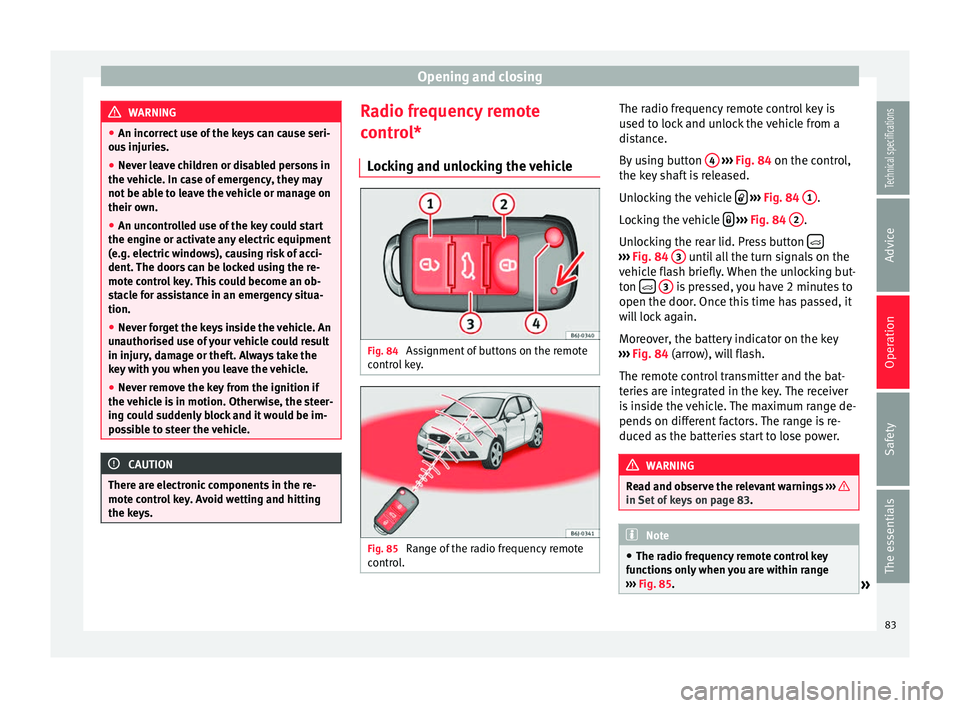
Locking and unlocking the vehicle Fig. 84
Assignment of buttons on the remote
control key. Fig. 85
Range of the radio frequency remote
control. The radio frequency remote control key is
used to lock and unlock the vehicle from a
distance.
By using button
4
››› Fig. 84 on the control,
the k ey
shaft is released.
Unlocking the vehicle
››› Fig. 84 1 .
Locking the vehicle
››› Fig. 84 2 .
Unlocking the rear lid. Press button ›››
Fig. 84 3 until all the turn signals on the
vehicle flash briefly. When the unlocking but-
ton
3 is pressed, you have 2 minutes to
open the door. Once this time has passed, it
will lock again.
Moreover, the battery indicator on the key
››› Fig. 84 (arrow), will flash.
The r emot
e control transmitter and the bat-
teries are integrated in the key. The receiver
is inside the vehicle. The maximum range de-
pends on different factors. The range is re-
duced as the batteries start to lose power. WARNING
Read and observe the relevant warnings ››› in Set of keys on page 83.
Note
● The radio frequency remote control key
functions only when you are within range
››› Fig. 85.
» 83
Technical specifications
Advice
Operation
Safety
The essentials
Page 89 of 240
Opening and closing
A warning appears on the instrument panel
display if the rear lid is open or not properly
closed.* An audible warning is also given if
the boot lid is opened while the vehicle is
moving faster than 6 km/h (4 mph)*. WARNING
● Always close the rear lid properly. Risk of
accident or injury.
● The rear lid must not be opened when the
reverse or rear fog lights are lit. This may
damage the tail lights.
● Do not close the rear lid by pushing it down
with your hand on the rear window. The glass
could smash. Risk of injury!
● Ensure the rear lid is locked after closing it.
If not, it may open unexpectedly while driv-
ing.
● Never allow children to play in or around
the vehicle. A locked vehicle can be subjected
to extremely high and low temperatures, de-
pending on the time of year, thus causing se-
rious injuries/illness. It could even have fatal
consequences. Close and lock both the rear
lid and all the other doors when you are not
using the vehicle.
● Closing the rear lid without observing and
ensuring it is clear could cause serious injury
to you and to third parties. Make sure that no
one is in the path of the rear lid.
● Never drive with the rear lid open or half-
closed, exhaust gases may enter into the in-
terior of the vehicle. Danger of poisoning! ●
If you only open the rear lid, do not leave
the key inside. The vehicle cannot be opened
if the key is left inside. Electric windows
Opening or closing the windows
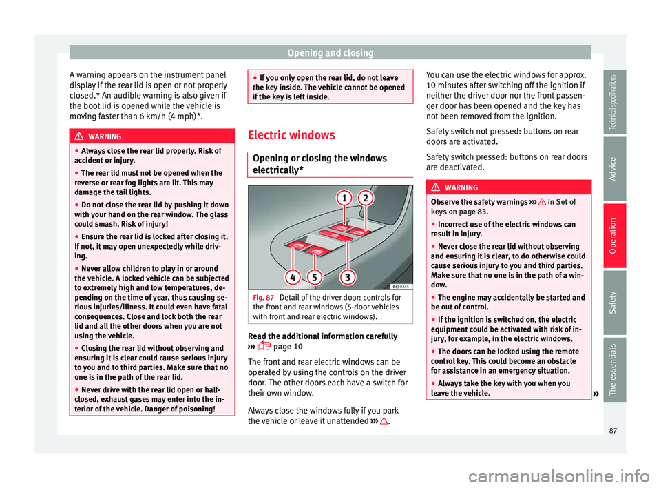
electrically* Fig. 87
Detail of the driver door: controls for
the front and rear windows (5-door vehicles
with front and rear electric windows). Read the additional information carefully
››› page 10
The front and rear electric windows can be
operated by using the controls on the driver
door. The other doors each have a switch for
their own window.
Always close the windows fully if you park
the vehicle or leave it unattended ››› .You can use the electric windows for approx.
10 minutes after switching off the ignition if
neither the driver door nor the front passen-
ger door has been opened and the key has
not been removed from the ignition.
Safety switch not pressed: buttons on rear
doors are activated.
Safety switch pressed: buttons on rear doors
are deactivated.
WARNING
Observe the safety warnings ››› in Set of
keys on page 83.
● Inc orr
ect use of the electric windows can
result in injury.
● Never close the rear lid without observing
and ensuring it is clear, to do otherwise could
cause serious injury to you and third parties.
Make sure that no one is in the path of a win-
dow.
● The engine may accidentally be started and
be out of control.
● If the ignition is switched on, the electric
equipment could be activated with risk of in-
jury, for example, in the electric windows.
● The doors can be locked using the remote
control key. This could become an obstacle
for assistance in an emergency situation.
● Always take the key with you when you
leave the vehicle. » 87
Technical specifications
Advice
Operation
Safety
The essentials
Page 91 of 240
Opening and closing
●
Closing the windows without observing and
ensuring it is clear could cause serious injury
to you and third parties. Make sure that no
one is in the path of a window.
● Never allow people to remain in the vehicle
when you close the vehicle from the outside.
The windows cannot be opened even in an
emergency.
● The roll-back function does not prevent fin-
gers or other parts of the body getting
pinched against the window frame. Risk of
accident. Convenience opening and closing*
Using the door lock*
– Hold the key in the door lock of the driver
door in either the locking or the unlocking
position until all windows are either
opened or closed.
– Release the key to interrupt this function.
Using the remote control
– Keep the locking/unlocking button pressed
for the electric window risers to
open/close; if you stop pressing the but-
ton, the window raising/lowering function
is stopped.
– If the automatic raising is stopped and im-
mediately after, the opening button is kept
pressed, the window risers will lower. –
Once the windows are completely closed,
the turn signals will flash.
Panoramic tilting sunroof* Opening or closing of the
panoramic/tilting sunroof Read the additional information carefully
››› page 10
The panoramic/tilting sunroof is opened and
closed by using the switch when the ignition
is switched on.
Always close the panoramic/tilting sunroof
fully if you park the vehicle or leave it unat-
tended ››› .
The tilting sunroof can be operated for up to
about ten minutes after the ignition has been
switched off, provided the driver door and
the front passenger door are not opened.
Sun visor
The sun visor is opened and closed manually
(independently of the panoramic/tilting sun-
roof). WARNING
● Incorrect use of the tilting sunroof can re-
sult in injury. ●
Never close the tilting sunroof without first
checking that there are no obstructions. Risk
of serious injury to you or others. Make sure
that no one is in the path of the tilting sun-
roof.
● Always take the vehicle key with you when
you leave the vehicle.
● Never leave children or disabled persons in
the vehicle, particularly if they have access to
the keys. Unsupervised use of a key could
mean that the engine is started or that elec-
trical equipment is used (e.g. electric tilting
sunroof) with a risk of accident. The doors
can be locked using the remote control key.
This could become an obstacle for assistance
in an emergency situation.
● The tilting sunroof continues to function
until one of the front doors is opened and the
key removed from the ignition.
● Ensure that no object and/or end is be-
tween the glass and the sunroof when the
one-touch opening/closing function is reset. Convenience closing*
Using the door lock
– Hold the key in the door lock of the driver
door in the locking position until the tilting
sunroof is closed.
– Release the key to interrupt this function.
»
89Technical specifications
Advice
Operation
Safety
The essentials
Page 98 of 240
Operation
Interior lights Front interior light Read the additional information carefully
››› page 15 Note
If not all the vehicle doors are closed, the in-
terior lights will be switched off after approx.
10 minutes, providing the ignition key has
been removed and the courtesy light position
selected. This prevents the battery from dis-
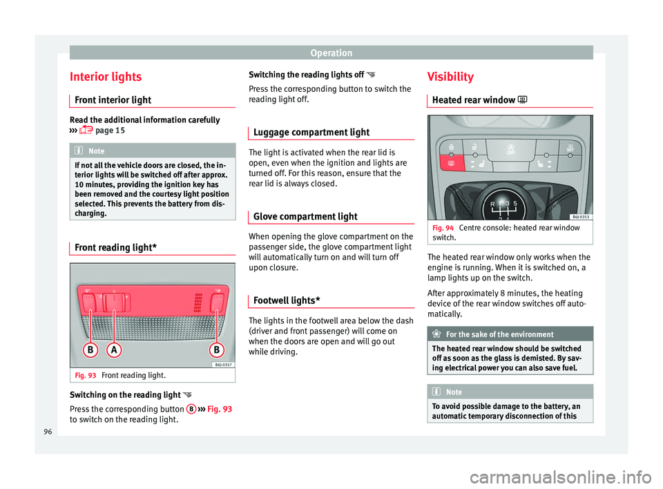
charging. Front reading light*
Fig. 93
Front reading light. Switching on the reading light
Press the corresponding button B
››› Fig. 93
to switch on the reading light. Switching the reading lights off
Press the corresponding button to switch the
reading light off.
Luggage compartment light The light is activated when the rear lid is
open, even when the ignition and lights are
turned off. For this reason, ensure that the
rear lid is always closed.
Glove compartment light When opening the glove compartment on the
passenger side, the glove compartment light
will automatically turn on and will turn off
upon closure.
Footwell lights* The lights in the footwell area below the dash
(driver and front passenger) will come on
when the doors are open and will go out
while driving.Visibility
Heated rear window Fig. 94
Centre console: heated rear window
switch. The heated rear window only works when the
engine is running. When it is switched on, a
lamp lights up on the switch.
After approximately 8 minutes, the heating
device of the rear window switches off auto-
matically.
For the sake of the environment
The heated rear window should be switched
off as soon as the glass is demisted. By sav-
ing electrical power you can also save fuel. Note
To avoid possible damage to the battery, an
automatic temporary disconnection of this 96
Page 104 of 240
Operation
WARNING
● Never drive if the head restraints have been
removed. Risk of injury.
● Never drive if the head restraints are in an
unsuitable position, there is a risk of serious
injury.
● After refitting the head restraint, you must
always adjust it properly for height to achieve
optimal protection.
● Please observe the safety warnings in ››› in Correct adjustment of front head restraints
on page 33.
Note
● To fit and remove the rear head restraints,
gently tilt the seat backrest forwards.
● When fitting the head restraints again, in-
sert the tubes as far as possible into the
guides without pressing the button. Seat functions
Heated seats* Fig. 100
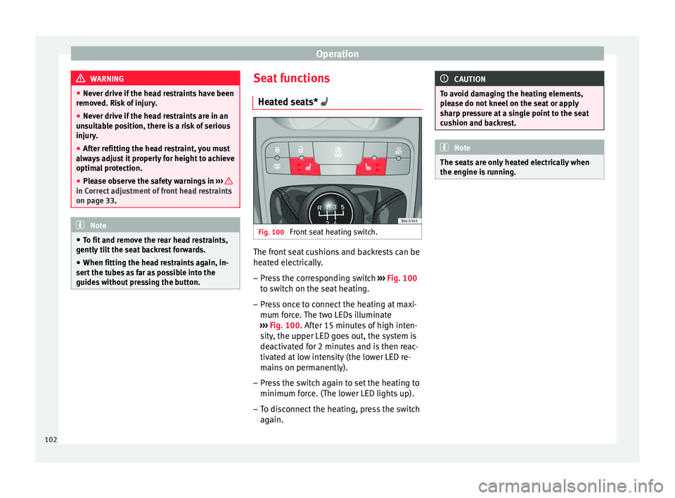
Front seat heating switch. The front seat cushions and backrests can be
heated electrically.
– Press the corresponding switch ››› Fig. 100
to switch on the seat heating.
– Press once to connect the heating at maxi-
mum force. The two LEDs illuminate
››› Fig. 100 . After 15 minutes of high inten-
s ity
, the upper LED goes out, the system is
deactivated for 2 minutes and is then reac-
tivated at low intensity (the lower LED re-
mains on permanently).
– Press the switch again to set the heating to
minimum force. (The lower LED lights up).
– To disconnect the heating, press the switch
again. CAUTION
To avoid damaging the heating elements,
please do not kneel on the seat or apply
sharp pressure at a single point to the seat
cushion and backrest. Note
The seats are only heated electrically when
the engine is running. 102
Page 109 of 240
Transport and practical equipment
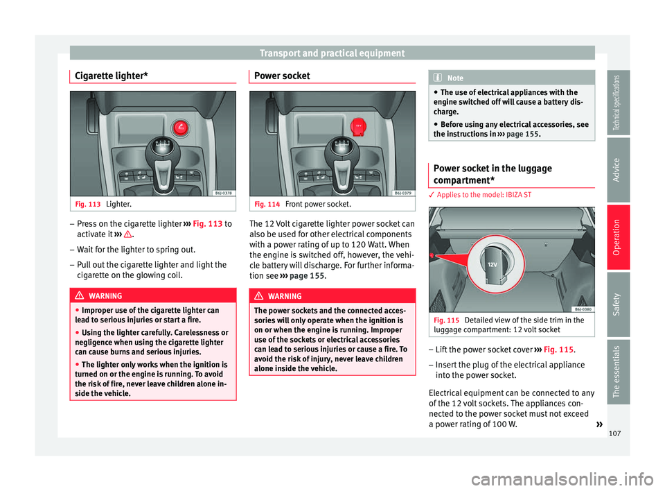
Cigarette lighter* Fig. 113
Lighter. –
Press on the cigarette lighter ››› Fig. 113 to
activ at
e it ››› .
– Wait for the lighter to spring out.
– Pull out the cigarette lighter and light the
cigarette on the glowing coil. WARNING
● Improper use of the cigarette lighter can
lead to serious injuries or start a fire.
● Using the lighter carefully. Carelessness or
negligence when using the cigarette lighter
can cause burns and serious injuries.
● The lighter only works when the ignition is
turned on or the engine is running. To avoid
the risk of fire, never leave children alone in-
side the vehicle. Power socket
Fig. 114
Front power socket. The 12 Volt cigarette lighter power socket can
also be used for other electrical components
with a power rating of up to 120 Watt. When
the engine is switched off, however, the vehi-
cle battery will discharge. For further informa-
tion see
››› page 155 . WARNING
The power sockets and the connected acces-
sories will only operate when the ignition is
on or when the engine is running. Improper
use of the sockets or electrical accessories
can lead to serious injuries or cause a fire. To
avoid the risk of injury, never leave children
alone inside the vehicle. Note
● The use of electrical appliances with the
engine switched off will cause a battery dis-
charge.
● Before using any electrical accessories, see
the instructions in ››› page 155. Power socket in the luggage
compartment*
3 Applies to the model: IBIZA ST
Fig. 115
Detailed view of the side trim in the
luggage compartment: 12 volt socket –
Lift the power socket cover ››› Fig. 115 .
– Inser
t the plug of the electrical appliance
into the power socket.
Electrical equipment can be connected to any
of the 12 volt sockets. The appliances con-
nected to the power socket must not exceed
a power rating of 100 W. »
107
Technical specifications
Advice
Operation
Safety
The essentials
Page 110 of 240
Operation
CAUTION
Always use the correct type of plugs to avoid
damaging the sockets. Note
● The power sockets will only work with the
ignition on.
● The use of electrical appliances with the
engine switched off will cause a battery dis-
charge. Auxiliary audio connection (AUX)*
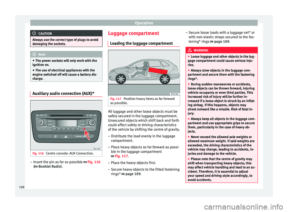
Fig. 116
Centre console: AUX Connection. –
Insert the pin as far as possible ››› Fig. 116
( ››› Booklet Radio ). L
ug gage compartment
Loading the luggage compartment Fig. 117
Position heavy items as far forward
as possible. All luggage and other loose objects must be
safely secured in the luggage compartment.
Unsecured objects which shift back and forth
could affect safety or driving characteristics
of the vehicle by shifting the centre of gravity.
– Distribute the load evenly in the luggage
compartment.
– Place heavy objects as far forward as possi-
ble in the luggage compartment
››› Fig. 117 .
– Plac
e the heavy objects first.
– Secure heavy objects to the fitted fastening
rings* ››› page 109. –
Secur
e loose loads with a luggage net* or
with non-elastic straps secured to the fas-
tening* rings ››› page 109. WARNING
● Loose luggage and other objects in the lug-
gage compartment could cause serious inju-
ries.
● Always stow objects in the luggage com-
partment and secure them with the fastening
rings*.
● During sudden manoeuvres or accidents,
loose objects can be thrown forward, injuring
vehicle occupants or even third parties. This
increased risk of injury will be further in-
creased if a loose object is struck by an inflat-
ing airbag. If this happens, objects may
shoot outward like a missile. Risk of fatal in-
jury.
● Always keep all objects in the luggage com-
partment and use appropriate grips to secure
them, particularly in the case of heavy ob-
jects.
● Never exceed the allowed axle weights or
allowed maximum weight. If said weights are
exceeded, the driving characteristics of the
vehicle may change, leading to accidents, in-
juries and damage to the vehicle.
● Please note that the centre of gravity may
shift when transporting heavy objects; this
may affect vehicle handling and lead to an ac-
cident. Therefore, it is essential to adjust
your speed and driving style accordingly, to
avoid accidents. 108
Page 116 of 240
Operation
Technical Service should be consulted to
check the system.
● To ensure correct operation, the grilles on
both sides of the screen must not be obstruc-
ted ●
When the engine is under extreme strain,
switch off the compressor for a moment. Heating
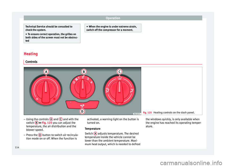
Controls Fig. 125
Heating controls on the dash panel. –
Using the controls A and
C and with the
switch B
››› Fig. 125 you can adjust the
t emper
ature, the air distribution and the
blower speed.
– Press the D button to switch air recircula-
tion mode on or off. When the function is activated, a warning light on the button is
turned on.
Temperature
Switch A adjusts temperature. The desired
temperature inside the vehicle cannot be
lower than the ambient temperature. Maxi-
mum heat output, which is needed to defrost the windows quickly, is only available when
the engine has reached its operating temper-
ature.
114