TSI SEAT IBIZA 5D 2017 Owners Manual
[x] Cancel search | Manufacturer: SEAT, Model Year: 2017, Model line: IBIZA 5D, Model: SEAT IBIZA 5D 2017Pages: 248, PDF Size: 5.24 MB
Page 4 of 248
Related videos
EcoTSI Engine
Ambient light and natural light››› page 118
››› page 122
Fatigue detection››› page 171
Page 11 of 248
The essentials
How it works
Openin g and c
lo
sing
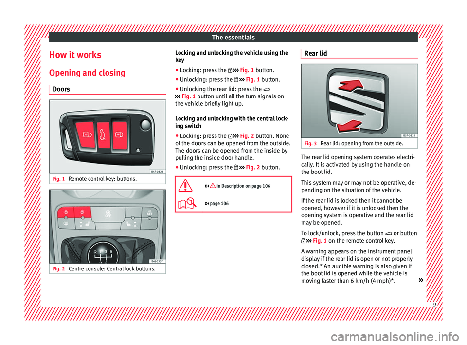
Doors Fig. 1
Remote control key: buttons. Fig. 2
Centre console: Central lock buttons. Locking and unlocking the vehicle using the
k
ey
● Loc
king: press the ›››
Fig. 1 button.
● Unlocking: press the ›››
Fig. 1 button.
● Unlocking the rear lid: press the
›››
Fig. 1 button until all the turn signals on
the vehicle briefly light up.
Locking and unlocking with the central lock-
ing switch
● Locking: press the ›››
Fig. 2 button. None
of the doors can be opened from the outside.
The doors can be opened from the inside by
pulling the inside door handle.
● Unlocking: press the ›››
Fig. 2 button.
››› in Description on page 106
››› page 106 Rear lid
Fig. 3
Rear lid: opening from the outside. The rear lid opening system operates electri-
c
al
ly
. It is activated by using the handle on
the boot lid.
This system may or may not be operative, de-
pending on the situation of the vehicle.
If the rear lid is locked then it cannot be
opened, however if it is unlocked then the
opening system is operative and the rear lid
may be opened.
To lock/unlock, press the button or button
››› Fig. 1 on the remote control key.
A warning appears on the instrument panel
display if the rear lid is open or not properly
closed.* An audible warning is also given if
the boot lid is opened while the vehicle is
moving faster than 6 km/h (4 mph)*. » 9
Page 29 of 248
The essentials
press button
or
several times
› ›
›
Fig. 37.
Select a submenu ● Press the rocker switch ›››
Fig. 36 2 on the
w ind
s
creen wiper lever up or down or turn
the thumbwheel of the multifunction steering
wheel ››› Fig. 37 until the desired option ap-
pears marked on the menu.
● The selected option is displayed between
two horizont
al lines. In addition, a triangle is
displayed on the right:
● To consult the submenu option, press but-
ton ››
› Fig. 36 1 on the windscreen wiper
l ev
er or b
utton on the multifunction steer-
in g wheel
›
›› Fig. 37.
Making changes according to the menu ● Make the desired changes with the rocker
switc
h on the windscreen wiper lever or the
thumbwheel of the multifunction steering
wheel. To increase or decrease the values
more quickly, turn the thumbwheel faster.
● Mark or confirm the selection with button
›››
Fig. 36 1 on the windscreen wiper lever
or b utt
on on the multifunction steering
wheel
›
›
› Fig. 37. Menu
MenuFunction
Driving
dataInformation and possible configura-
tions of the multifunction display (MFD)
››› page 29, ››› page 99.
Assist
systemsInformation and possible configura-
tions of the driver assistance systems
››› page 99.
Navigation
Information instructions from the acti-
vated navigation system: when a route
guidance is activated, the turning ar-
rows and proximity bars are displayed.
The appearance is similar to the Easy
Connect system.
If route guidance is not activated, the
direction of travel (compass) and the
name of the street along which you are
driving are shown ››› Booklet Naviga-
tion system.
Audio
Station display on the radio.
Track name on the CD.
Track name in Media mode ››› Book-
let Radio or ››› Booklet Navigation sys-
tem.
Telephone
Information and possible configura-
tions of the mobile phone preinstalla-
tion ››› Booklet Radio or ››› Booklet Nav-
igation system.
Lap timer *
In a racing circuit, measurement and
memorisation of lap times by the vehi-
cle and comparison with previously
measured best times ››› page 31.
MenuFunction
Vehicle
statusDisplay of the current warning or infor-
mation texts and other system compo-
nents, depending on the equipment
››› page 99. Outside temperature display
When the outside temperature is below +4°C
(+39°F), the “ice c
r
ystal” symbol (warning of
risk of freezing) is also displayed. At first, this
symbol flashes and then it remains lit until
the outside temperature rises above +6°C
(+43°F) ››› in Indications on the display on
p ag
e 96
.
When the vehicle is at a standstill or when
travelling at very low speeds, the tempera-
ture displayed may be higher than the true
outside temperature as a result of the heat
produced by the engine.
The temperatures measured range from
-40°C to +50°C (-40°F to +122°F). 27
Page 33 of 248
The essentials
● To sw
it
ch system on: adjust to the desired
speed within 5 seconds using the rocker
switch on the windscreen wiper lever or
b y
t
urning the thumbwheel on the multifunc-
tion steering wheel. Next, press the button or
again or wait several seconds.
The s peed i
s
stored and the warning activa-
ted.
● To switch system off: press the but-
ton or
. The stored speed is de-
l et
ed.
En
gine oil temperature display The engine reaches its operating temperature
when in norm
al
driv
ing conditions, the oil
temperature is between 80°C (178°F) and
120°C (248°F). If the engine is required to
work hard and the outside temperature is
high, the engine oil temperature can in-
crease. This does not present any problem as
long as the warning lamps ›››
table on
page 36 or ›››
table on page 36 do not
appear on the display.
Vehicles without multifunction steering
wheel
● Press the rocker switch ›››
Fig. 36 2 until
the m ain menu ap
pe
ars. Enter into Driving
data . With the button 2 move to the oil
t emper
at
ure gauge. Vehicles with multifunction steering wheel
●
Enter the submenu Driving data and
turn the thumbwheel
until the oil tempera-
ture display appears.
Additional electrical appliances ●
Operation with the windscreen wiper lever*:
Pre s
s the rocker switch ››› Fig. 36 2 until the
main menu ap pe
ars. Enter into the section
Driving data . With the rocker switch,
move to the display Convenience con-
sumers .
● Operation with the multi-function steering
whee l*:
Move with the buttons 1 or
2 to
Driving data and enter w
ith
OK . Turn the
thumbwheel to the right until the Conven-
ience consumers display appears.
In addition, a scale will inform you of the cur-
rent sum of all the additional appliances.
Saving tips Tips on how to save fuel will be displayed in
c
ondition
s
that increase fuel consumption.
Follow them to reduce consumption. The indi-
cations appear automatically only with the ef-
ficiency programme. After a time, the tips will
disappear automatically. If you wish to hide a saving tip immediately
after it
appears, press any button on the
windscreen wiper lever*/multifunction steer-
ing wheel*. Note
● If y
ou hide a saving tip, it will reappear af-
ter you switch the ignition on again.
● The saving tips do not appear in all situa-
tions, but
rather with a large separation of
time. Timer*
You can access the timer via the selection
menu
››
›
page 27.
It allows you to manually time lap times on a
racing circuit, memorise them and compare
them to the vehicle's previous best times.
The following menus can be displayed:
● Stop
● Lap
● Pause
● Partial time
● Statistics » 31
Page 39 of 248
The essentials
Fault in the battery.›››
page
207
Driving light totally or partially
faulty.›››
page
83
Fault in the cornering light sys-
tem.››› page
117
Diesel particulate filter blocked›››
page
167
Level of windscreen washer fluid
too low.›››
page
207
Flashing: Fault in the oil level de-
tection. Control manually.›››
page
201
Ignition: Insufficient engine oil.
Fault in the gearbox.›››
page
163
Immobiliser active.›››
page
147
Service interval display›››
page
33
Mobile telephone is connected
via Bluetooth to the original tele-
phone device.›››
Book-
let Radio
or
››› Book-
let Navi-
gation
system
Mobile telephone battery charge
meter. Available only for devices
pre-installed in factory.
Freezing warning. The outside
temperature is lower than +4°C
(+39°F).›››
page
27
Start-Stop system activated.›››
page
170
Start-Stop system unavailable.
Low consumption driving status›››
page
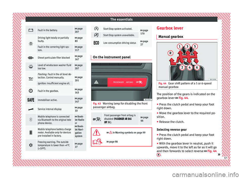
27 On the instrument panel
Fig. 43
Warning lamp for disabling the front
p a
s
senger airbag.
Front passenger front airbag is
disabled (
).
››› page
66
››› in Warning symbols on page 99
›››
page 98 Gearbox lever
M anua
l
gearbox Fig. 44
Gear shift pattern of a 5 or 6-speed
m anual
g
earbox The position of the gears is indicated on the
g
e
arbo
x lever ››› Fig. 44.
● Press the clutch pedal and keep your foot
right down.
● Mo
ve the gearbox lever to the required po-
sition.
● Rel
ease the clutch.
Selecting r
everse gear
● Press the clutch pedal and keep your foot
right down.
● W
ith the gearbox lever in neutral, push it
upwar
ds, move it to the left as far as it will go
and then forwards to select reverse ››› Fig. 44
R .
» 37
Page 60 of 248
Safety
●
Adjus t
the driver's seat so that there is at
least 25 cm distance between the centre of
the chest and the centre of the steering
wheel ››› Fig. 74. If distance is less than 25
cm, the airbag system may not protect you
properly.
● If your physical constitution prevents you
from maint
aining the minimum distance of 25
cm, contact a specialised workshop. The
workshop will help you decide if special spe-
cific modifications are necessary.
● When driving, always hold the steering
wheel with both h
ands on the outside of the
ring at the 9 o'clock and 3 o'clock positions.
This reduces the risk of injury when the driver
airbag is triggered.
● Never hold the steering wheel at the 12
o'clock
position, or in any other manner (e.g.
in the centre of the steering wheel). In such
cases, if the airbag is triggered, you may sus-
tain injuries to the arms, hands and head.
● To reduce the risk of injury to the driver
during sud
den braking manoeuvres or an ac-
cident, never drive with the backrest tilted far
back! The airbag system and seat belts can
only provide optimal protection when the
backrest is in an upright position and the
driver is wearing his or her seat belt correct-
ly.
● Adjust the head restraint properly to ach-
ieve optima
l protection. Adjusting the steering wheel position
Read the additional information carefully
›› ›
page 13 WARNING
● Never a dju
st the position of the steering
wheel when the vehicle is moving, as this
could cause an accident.
● Move the lever up firmly so the steering
wheel pos
ition does not accidentally change
during driving. risk of accident!
● Make sure you are capable of reaching and
firmly ho
lding the upper part of the steering
wheel: risk of accident!
● If you adjust the steering wheel so that it
points t
owards your face, the driver airbag
will not protect you properly in the event of
an accident. Make sure that the steering
wheel points towards your chest. Correct sitting position for front pas-
sen
g
er For your own safety and to reduce the risk of
injur
y
in the ev
ent of an accident, we recom-
mend the following adjustments for the front
passenger:
– Move the front passenger seat back as far
as po
ssible ››› .–
Mo v
e the se
at backrest to an upright posi-
tion so that your back rests completely
against it.
– Adjust the head restraint so that its upper
edge is
at the same level as the top of your
head, or as close as possible to the same
level as the top of your head ››› page 60.
– Always keep both feet in the footwell in
front of
the front passenger seat.
– Fasten your seat belt securely ›››
page 61.
It is possible to deactivate the front passen-
ger airbag in exceptional circumstances
››› page 70.
Adjusting the front passenger seat
››› page 12. WARNING
● An incorr ect
sitting position of the front
passenger can lead to severe injuries.
● Adjust the front passenger seat so that
there is
at least 25 cm between your chest
and the dash panel. If distance is less than
25 cm, the airbag system may not protect you
properly.
● If your physical constitution prevents you
from maint
aining the minimum distance of 25
cm, contact a specialised workshop. The
workshop will help you decide if special spe-
cific modifications are necessary. 58
Page 78 of 248
Emergencies
changed with the temporary spare wheel
fr om another
v
ehicle.
No other type of tyre (normal summer or win-
ter tyre) may be fitted on the compact tempo-
rary spare wheel rim.
Snow chains
For technical reasons, snow chains must not
be used on the temporary spare wheel.
If you have a puncture on one of the front
wheels when using snow chains, fit the tem-
porary spare wheel in place of one of the rear
wheels. Fit the snow chains on the rear wheel
that you have removed and replace the punc-
tured front wheel with this wheel.
Extraction of the spare wheel in vehicles
with SEAT SOUND 6 speakers (with subwoof-
er)*
● Disassemble the subwoofer's
floor panel
(carpet) as follows:
● Pull the carpet upwards to remove it.
● Disconnect the subwoofer's
speaker cable.
● Turn the securing wheel anti-clockwise.
● Remove the subwoofer
speaker and the
spare wheel.
● When replacing the spare wheel, place the
subwoofer
speaker in the direction indicated
by the arrow and with the word “FRONT” fac-
ing forward. ●
Reconnect
the speaker cable and firmly ro-
tate the securing wheel clockwise so that the
subwoofer system and wheel are firmly in
place. WARNING
● Aft er fittin
g the temporary spare wheel,
check the tyre pressures as soon as possible.
Failure to do so may cause an accident. The
tyre pressures are listed on the inside of the
fuel tank flap.
● Do not drive at over 80 km/h (50 mph)
when the temporar
y spare wheel is fitted on
the vehicle: risk of accident!
● Avoid heavy acceleration, hard braking and
fas
t cornering: risk of accident!
● Never use more than one temporary spare
wheel at the s
ame time, risk of accident.
● No other type of tyre (normal summer or
winter ty
re) may be fitted on the compact
temporary spare wheel rim. Tyre repair
TM S
(T
yre Mobility System)* Read the additional information carefully
› ›
›
page 46
The Anti-puncture kit* (Tyre Mobility System)
will reliably seal punctures caused by the
penetration of a foreign body of up to about 4 mm in diameter. Do not remove foreign ob-
ject
s, e.g. screws or nails, from the tyre.
After inserting the sealant residue in the tyre,
you must again check the tyre pressure about
10 minutes after starting the engine.
You should only use the tyre mobility set if
the vehicle is parked in a safe place, you are
familiar with the procedure and you have the
necessary tyre mobility set! Otherwise, you
should seek professional assistance.
Do not use the tyre sealant in the following
cases:
● If the wheel rim has been damaged.
● In outside temperatures below -20°C (-4°F).
● In the event of cuts or perforations in the
tyre gr
eater than 4 mm.
● If you have been driving with very low pres-
sure or a c
ompletely flat tyre.
● If the sealant bottle has passed its use by
date. WARNING
Using the tyre mobility system can be dan-
ger ou
s, especially when filling the tyre at the
roadside. Please observe the following rules
to minimise the risk of injury:
● Stop the vehicle safely as soon as possible.
Park it
at a safe distance from surrounding
traffic to fill the tyre. 76
Page 97 of 248
Instruments and warning/control lamps
CAUTION
● To pr ev
ent damage to the engine, the rev
counter needle should only remain in the red
zone for a short period of time.
● When the engine is cold, avoid high revs
and heavy ac
celeration and do not make the
engine work hard. For the sake of the environment
Changing up a gear in time reduces fuel con-
sumption and noi se.Rev counter
The rev counter indicates the number of en-
gine r
ev
o
lutions per minute ›››
Fig. 113 1 .
T og
ether w
ith the gear-change indicator, the
rev counter offers you the possibility of using
the engine of your vehicle at a suitable
speed.
The start of the red zone on the dial indicates
the maximum engine speed which may be
used briefly when the engine is warm and af-
ter it has been run in properly. Before reach-
ing this range, you should change to a higher
gear for vehicles with a manual gearbox or for
automatic gearboxes put the selector lever in
“D” or take your foot off the accelerator ped-
al. We recommend that you avoid high revs and
that
you follow the recommendations on the
gear-change indicator. Consult the additional
information in ›››
page 28, Gear-change
indicator. CAUTION
Never allow the rev counter needle 1 ›››
Fig. 113 to g o int
o the red zone on the
scale for more than a very brief period, other-
wise there is a risk of engine damage. For the sake of the environment
Changing up a gear early will help you to save
fuel and minimi
se emissions and engine
noise. Indications on the display
A variety of information can be viewed on the
in
s
trument
panel display ›››
Fig. 113 3 de-
pendin g on the
v
ehicle equipment:
● Bonnet, rear lid and doors open
›››
page 28.
● Information and warning texts.
● Mileage.
● Time.
● Navigation instructions.
● Outside temperature.
● Compass. ●
Shift l
ever position ››› page 158.
● Recommended gear (manual gearbox)
›››
page 28.
● Multifunction display (MFD) and menus
with differ
ent setting options ›››
page 25.
● Service interval display ›››
page 33.
● Second speed display ›››
page 25.
● Speed warning function ›››
page 32.
● Start-Stop system status display
›››
page 170.
● Low consumption driving status (ECO)
›››
page 96
● Identifying letters on engine (MKB).
● Active cylinder management display
(ACT ®
)* ››
› page 165
Distance travelled
The odometer registers the total distance
travelled by the car.
The odometer (trip ) shows the distance
travelled since the last odometer reset. The
last digit of the trip recorder indicates distan-
ces of 100 metres or one tenths of a mile.
● Briefly press the button ›››
Fig. 113 4 to re-
set the trip r
ec
order to 0.
● Keep the button 4 pressed for about 3
sec ond
s
and the previous value will be dis-
played. »
95
Technical data
Advice
Operation
Emergencies
Safety
Page 98 of 248
Operation
Time
● To set the time, keep the button ››
› Fig. 113
4 pressed for more than 3 seconds to select
the hour or minut e di
s
play.
● To continue setting the time, press the up-
per or lower p
art of the button 4 . Hold but-
t on do
wn t
o scroll through the numbers
quickly.
● Press the button 4 again in order to finish
settin g the time.
The time c an al
so be set via the key and
Set up function button in the Easy Connect
sy s
t
em ››› page 99.
Compass
With the ignition on and the navigation sys-
tem on, the cardinal point corresponding to
the direction of travel of the vehicle is dis-
played on the instrument panel.
Selector lever position
The selected gear is displayed on the side of
the selector lever and on the instrument pan-
el display. In positions D and S, and with the
Tiptronic, the corresponding gear is also dis-
played.
Recommended gear (manual gearbox)
The recommended gear in order to save fuel
is displayed on the instrument panel while
you are driving ›››
page 28. Second speed display (mph or km/h)
In addition t
o the speedometer, the speed
can also be displayed in a different unit of
measurement (in miles or in km per hour).
This option cannot be deactivated in models
destined for countries in which the second
speed must always be visible.
The second speed display can be adjusted in
the Easy Connect system via the key and
the Set
up function button
››
›
page 99.
Speed warning
When the speed setting is exceeded, this will
be indicated on the instrument panel display.
This is very useful, for example when using
winter tyres that are not designed for driving
at the maximum speed of the vehicle
››› page 32.
The speed warning settings can be adjusted
in the Easy Connect system via the key
and the Set
up function button
››
›
page 99.
Start-Stop operating display
Updated information relating to the status is
displayed on the instrument panel
››› page 170.
Low consumption driving status (ECO)*
Depending on the equipment, when driving,
the “ECO ” display appears on the instrument
panel when the vehicle is in low consump- tion status due to active cylinder manage-
ment (A
CT®
)* ›››
page 30.
Identifying letters on engine (MKB)
Hold the button ››› Fig. 113 4 down for more
th an 15 sec
ond
s to display the identifying
letters of the vehicle engine (MKB). To do
this, the ignition must be switched on and
the engine switched off. WARNING
Observe the safety warnings ›››
in Warning
symbol s on p
age 99. WARNING
Even though outside temperatures are above
freez in
g, some roads and bridges may be icy.
● At outside temperatures above +4°C
(+39°F), even when the “ice c
rystal symbol”
is not visible, there may still be patches of ice
on the road.
● Do not rely on the outside temperature in-
dicator! Note
● Differ ent
versions of the instrument panel
are available and therefore the versions and
instructions on the display may vary. In the
case of displays without warning or informa-
tion texts, faults are indicated exclusively by
the warning lamps. 96
Page 99 of 248
Instruments and warning/control lamps
●
Dependin g on the equipment, some set
-
tings and instructions can also be carried out
in the Easy Connect system.
● When several warnings are active at the
same time, the symbol
s are shown succes-
sively for a few seconds and will stay on until
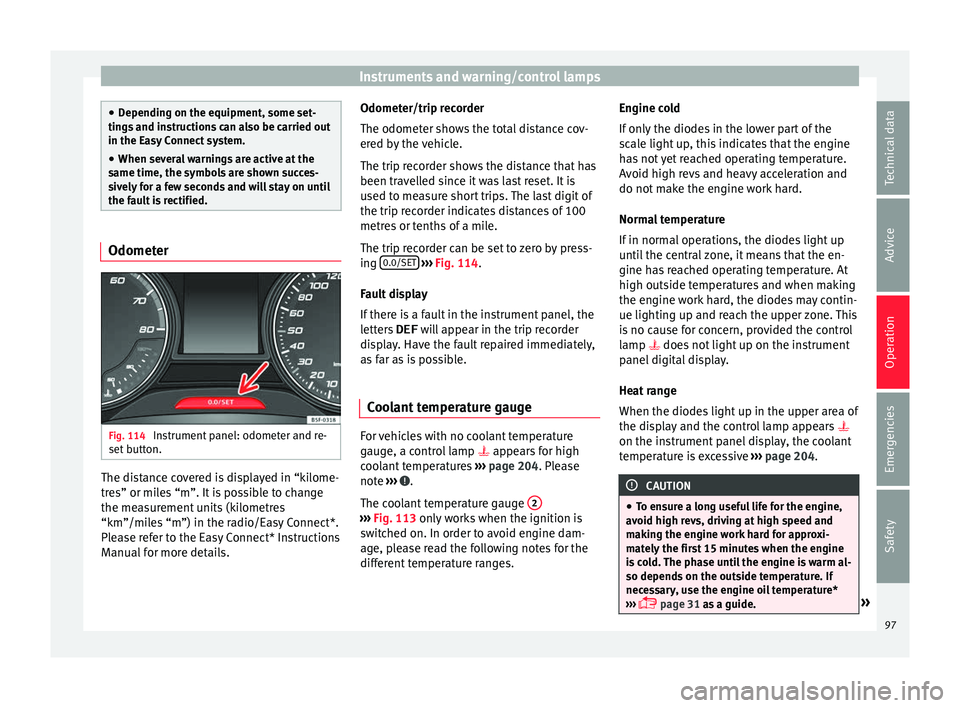
the fault is rectified. Odometer
Fig. 114
Instrument panel: odometer and re-
set b
utt
on. The distance covered is displayed in “kilome-
tr
e
s” or mi
les “m”. It is possible to change
the measurement units (kilometres
“km”/miles “m”) in the radio/Easy Connect*.
Please refer to the Easy Connect* Instructions
Manual for more details. Odometer/trip recorder
The odometer show
s the total distance cov-
ered by the vehicle.
The trip recorder shows the distance that has
been travelled since it was last reset. It is
used to measure short trips. The last digit of
the trip recorder indicates distances of 100
metres or tenths of a mile.
The trip recorder can be set to zero by press-
ing 0.0/SET
› ››
Fig. 114
.
F
ault display
If there is a fault in the instrument panel, the
letters DEF will appear in the trip recorder
display. Have the fault repaired immediately,
as far as is possible.
Coolant temperature gauge For vehicles with no coolant temperature
g
aug
e, a c
ontrol lamp appears for high
coolant temperatures ›››
page 204. Please
note ››› .
The c oo
l
ant temperature gauge 2 ›››
Fig. 113 only w
orks when the ignition is
switched on. In order to avoid engine dam-
age, please read the following notes for the
different temperature ranges. Engine cold
If on
ly
the diodes in the lower part of the
scale light up, this indicates that the engine
has not yet reached operating temperature.
Avoid high revs and heavy acceleration and
do not make the engine work hard.
Normal temperature
If in normal operations, the diodes light up
until the central zone, it means that the en-
gine has reached operating temperature. At
high outside temperatures and when making
the engine work hard, the diodes may contin-
ue lighting up and reach the upper zone. This
is no cause for concern, provided the control
lamp does not light up on the instrument
panel digital display.
Heat range
When the diodes light up in the upper area of
the display and the control lamp appears
on the instrument panel display, the coolant
temperature is excessive ››› page 204. CAUTION
● To en s
ure a long useful life for the engine,
avoid high revs, driving at high speed and
making the engine work hard for approxi-
mately the first 15 minutes when the engine
is cold. The phase until the engine is warm al-
so depends on the outside temperature. If
necessary, use the engine oil temperature*
››› page 31 as a guide. » 97
Technical data
Advice
Operation
Emergencies
Safety