light Seat Ibiza SC 2012 Owner's manual
[x] Cancel search | Manufacturer: SEAT, Model Year: 2012, Model line: Ibiza SC, Model: Seat Ibiza SC 2012Pages: 280, PDF Size: 3.67 MB
Page 233 of 280
231
If and when
– Move the loop ⇒ Fig. 144 1
in the direction of the arrow and
remove the cover.
– Remove the bulb holder 4
⇒ Fig. 146 outwards.
– Replace the bulb by pulling it out and inserting the replace-
ment.
– Installation is done in the reverse order.
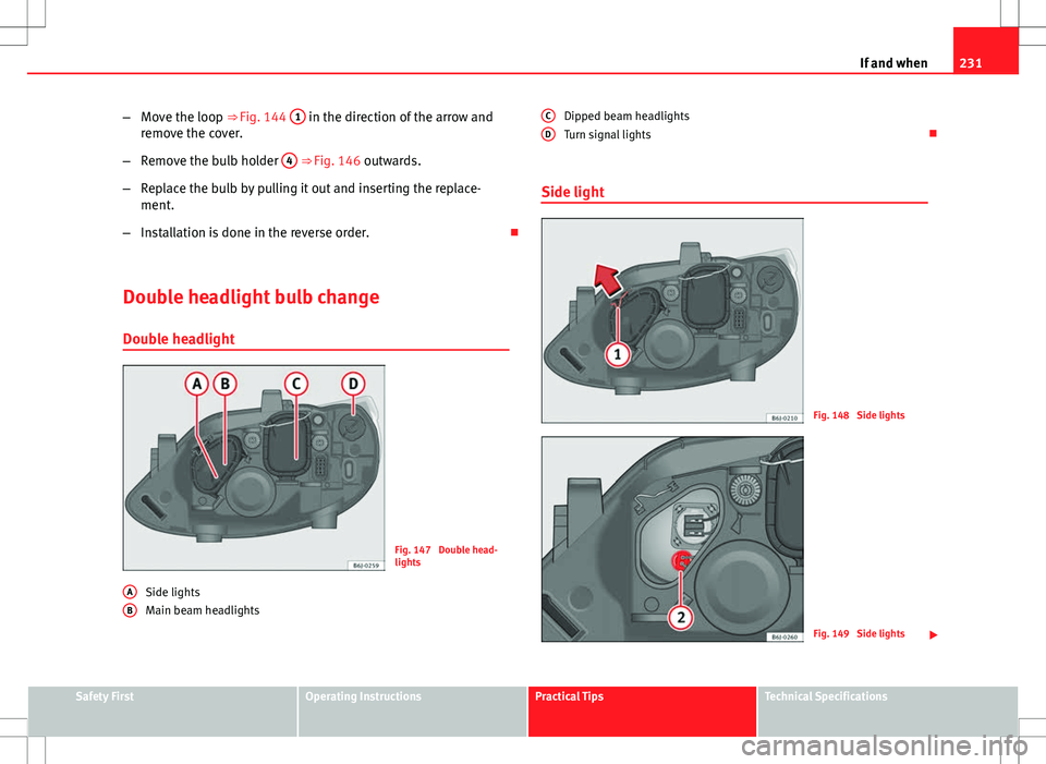
Double headlight bulb change Double headlight
Fig. 147 Double head-
lights
Side lights
Main beam headlights
A
B
Dipped beam headlights
Turn signal lights
Side light
Fig. 148 Side lights
Fig. 149 Side lights
C
D
Safety FirstOperating InstructionsPractical TipsTechnical Specifications
Page 234 of 280
232If and when
–Raise the bonnet.
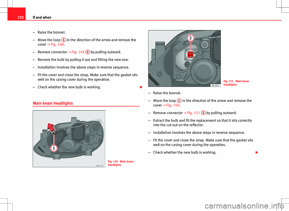
– Move the loop 1
in the direction of the arrow and remove the
cover ⇒ Fig. 148.
– Remove connector ⇒ Fig. 149 2
by pulling outward.
– Remove the bulb by pulling it out and fitting the new one.
– Installation involves the above steps in reverse sequence.
– Fit the cover and close the strap. Make sure that the gasket sits
well on the casing cover during the operation.
– Check whether the new bulb is working.
Main beam headlights
Fig. 150 Main beam
headlights
Fig. 151 Main beam
headlights
– Raise the bonnet.
– Move the loop 1
in the direction of the arrow and remove the
cover ⇒ Fig. 150.
– Remove connector ⇒ Fig. 151 2
by pulling outward.
– Extract the bulb and fit the replacement so that it sits correctly
into the cut-out on the reflector.
– Installation involves the above steps in reverse sequence.
– Fit the cover and close the strap. Make sure that the gasket sits
well on the casing cover during the operation.
– Check whether the new bulb is working.
Page 235 of 280
233
If and when
Dipped beam headlights
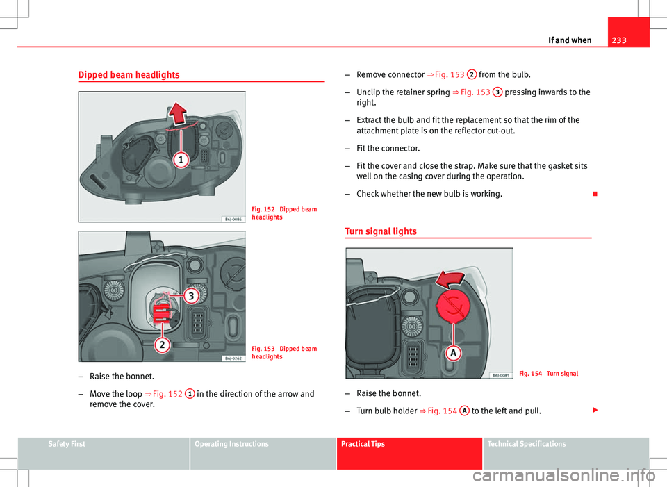
Fig. 152 Dipped beam
headlights
Fig. 153 Dipped beam
headlights
– Raise the bonnet.
– Move the loop ⇒ Fig. 152 1
in the direction of the arrow and
remove the cover. –
Remove connector ⇒ Fig. 153 2
from the bulb.
– Unclip the retainer spring ⇒ Fig. 153 3
pressing inwards to the
right.
– Extract the bulb and fit the replacement so that the rim of the
attachment plate is on the reflector cut-out.
– Fit the connector.
– Fit the cover and close the strap. Make sure that the gasket sits
well on the casing cover during the operation.
– Check whether the new bulb is working.
Turn signal lights
Fig. 154 Turn signal
– Raise the bonnet.
– Turn bulb holder ⇒ Fig. 154 A
to the left and pull.
Safety FirstOperating InstructionsPractical TipsTechnical Specifications
Page 237 of 280
235
If and when
Changing the bulbs of AFS headlights
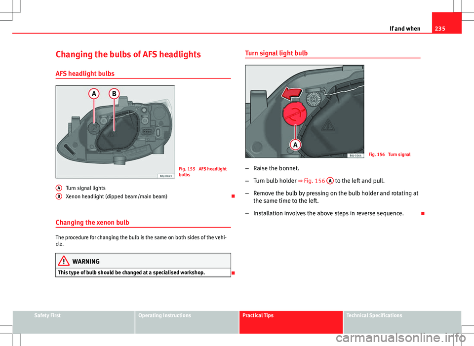
AFS headlight bulbs
Fig. 155 AFS headlight
bulbs
Turn signal lights
Xenon headlight (dipped beam/main beam)
Changing the xenon bulb
The procedure for changing the bulb is the same on both sides of the vehi-
cle.
WARNING
This type of bulb should be changed at a specialised workshop.
A
B
Turn signal light bulb
Fig. 156 Turn signal
– Raise the bonnet.
– Turn bulb holder ⇒ Fig. 156 A
to the left and pull.
– Remove the bulb by pressing on the bulb holder and rotating at
the same time to the left.
– Installation involves the above steps in reverse sequence.
Safety FirstOperating InstructionsPractical TipsTechnical Specifications
Page 238 of 280
236If and when
Changing the fog light bulbs
Fog light bulb
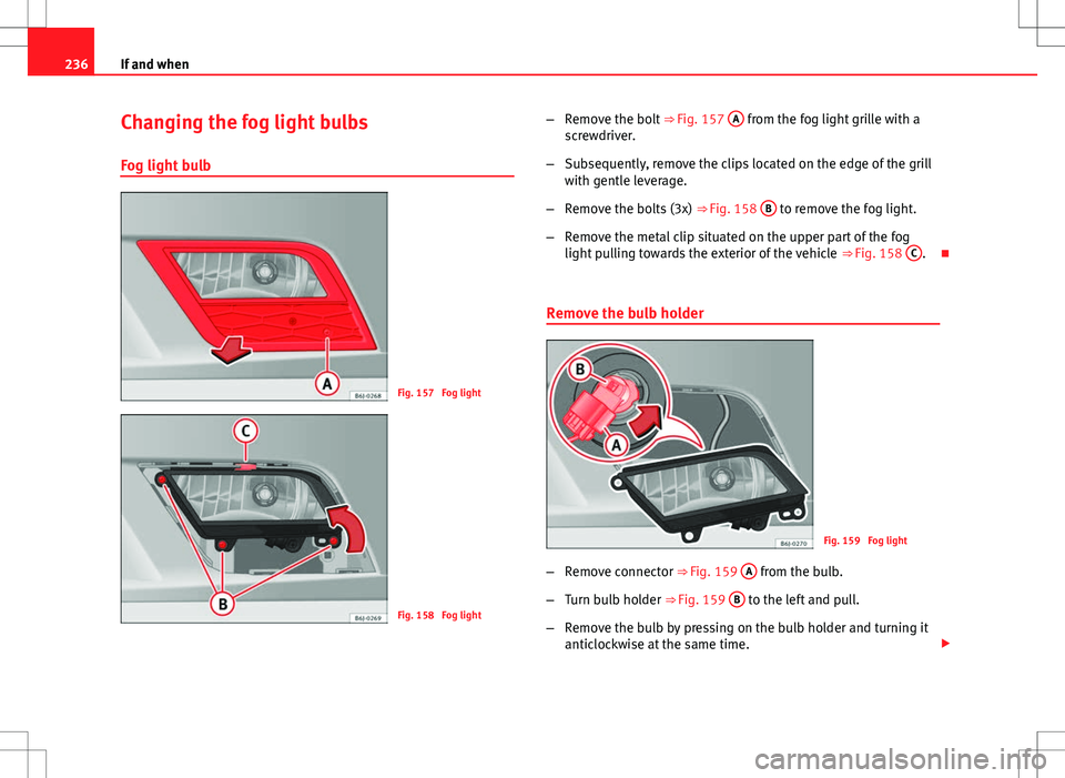
Fig. 157 Fog light
Fig. 158 Fog light –
Remove the bolt ⇒ Fig. 157 A
from the fog light grille with a
screwdriver.
– Subsequently, remove the clips located on the edge of the grill
with gentle leverage.
– Remove the bolts (3x) ⇒ Fig. 158 B
to remove the fog light.
– Remove the metal clip situated on the upper part of the fog
light pulling towards the exterior of the vehicle ⇒ Fig. 158 C
.
Remove the bulb holder
Fig. 159 Fog light
– Remove connector ⇒ Fig. 159 A
from the bulb.
– Turn bulb holder ⇒ Fig. 159 B
to the left and pull.
– Remove the bulb by pressing on the bulb holder and turning it
anticlockwise at the same time.
Page 239 of 280
237
If and when
– Installation involves the above steps in reverse sequence.
– Check that the bulb works properly.
Changing the rear, side and interior light
bulbs Summary of LED tail lights
LEDS
● Brake lights
● Side lights
Bulbs
● Rear fog light
● Reversing light
● Turn signal Tail lights
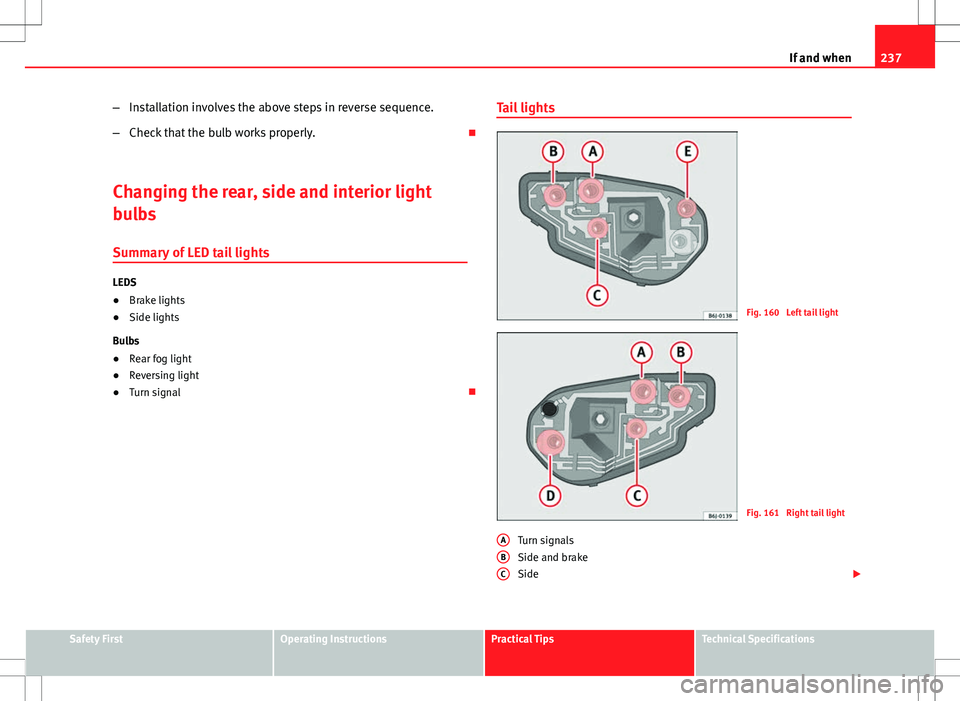
Fig. 160 Left tail light
Fig. 161 Right tail light
Turn signals
Side and brake
Side
A
BC
Safety FirstOperating InstructionsPractical TipsTechnical Specifications
Page 240 of 280
238If and when
Retro-fog light (left tail light)
Reverse light (right tail light)
Note
In countries driving on the right (left-driving), both D and E headlights are
placed the other way round (Retro-fog light on driver side and reverse light
on passenger side).
Access to tail lights
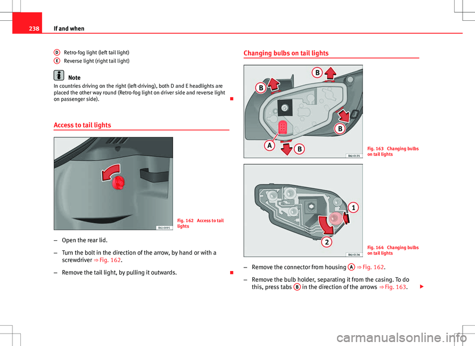
Fig. 162 Access to tail
lights
– Open the rear lid.
– Turn the bolt in the direction of the arrow, by hand or with a
screwdriver ⇒
Fig. 162.
– Remove the tail light, by pulling it outwards.
D
EChanging bulbs on tail lights
Fig. 163 Changing bulbs
on tail lights
Fig. 164 Changing bulbs
on tail lights
– Remove the connector from housing A
⇒ Fig. 162.
– Remove the bulb holder, separating it from the casing. To do
this, press tabs B
in the direction of the arrows
⇒ Fig. 163.
Page 241 of 280
239
If and when
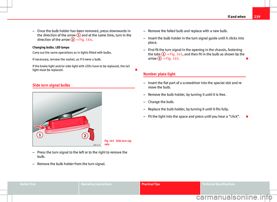
– Once the bulb holder has been removed, press downwards in
the direction of the arrow 1
and at the same time, turn in the
direction of the arrow 2 ⇒ Fig. 164.
Changing bulbs. LED lamps
Carry out the same operations as in lights fitted with bulbs.
If necessary, remove the socket, as if it were a bulb.
If the brake light and/or side light with LEDs have to be replaced, the tail
light must be replaced.
Side turn signal bulbs
Fig. 165 Side turn sig-
nals
– Press the turn signal to the left or to the right to remove the
bulb.
– Remove the bulb holder from the turn signal. –
Remove the failed bulb and replace with a new bulb.
– Insert the bulb holder in the turn signal guide until it clicks into
place.
– First fit the turn signal in the opening in the chassis, fastening
the tabs 1
⇒ Fig. 165, and then fit in the bulb as shown by the
arrow 2 ⇒ Fig. 165.
Number plate light
– Insert the flat part of a screwdriver into the special slot and re-
move the bulb.
– Remove the bulb holder, by turning it until it is free.
– Change the bulb.
– Replace the bulb holder, by turning it until it fits fully.
– Fit the light into the space and press until you hear a “click”.
Safety FirstOperating InstructionsPractical TipsTechnical Specifications
Page 242 of 280
240If and when
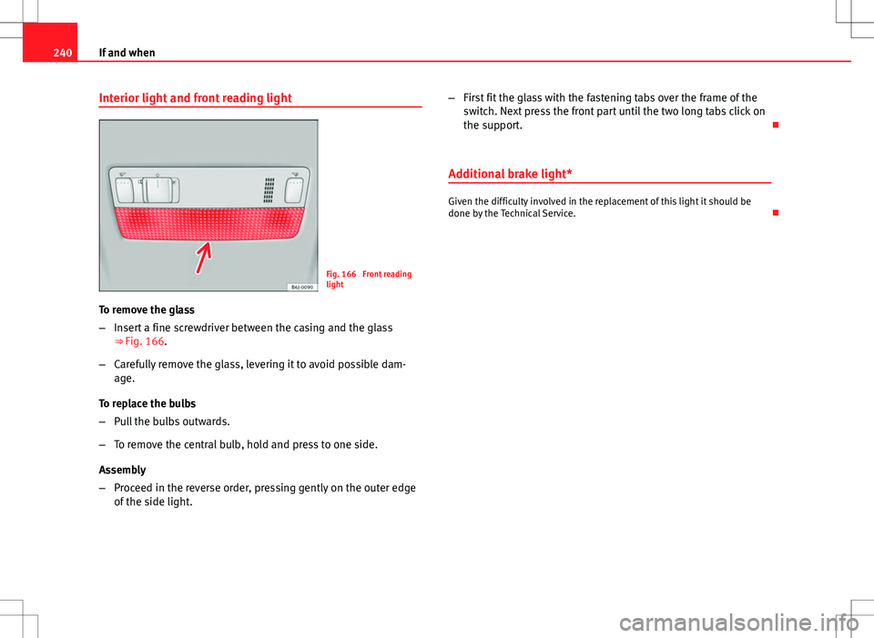
Interior light and front reading light
Fig. 166 Front reading
light
To remove the glass
– Insert a fine screwdriver between the casing and the glass
⇒ Fig. 166.
– Carefully remove the glass, levering it to avoid possible dam-
age.
To replace the bulbs
– Pull the bulbs outwards.
– To remove the central bulb, hold and press to one side.
Assembly
– Proceed in the reverse order, pressing gently on the outer edge
of the side light. –
First fit the glass with the fastening tabs over the frame of the
switch. Next press the front part until the two long tabs click on
the support.
Additional brake light*
Given the difficulty involved in the replacement of this light it should be
done by the Technical Service.
Page 243 of 280
241
If and when
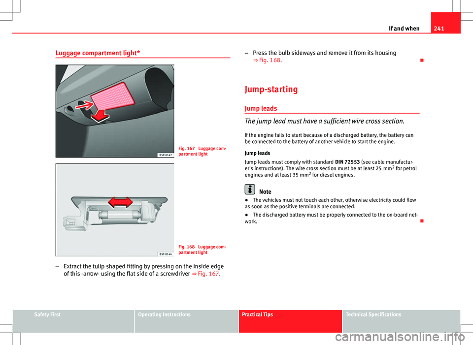
Luggage compartment light*
Fig. 167 Luggage com-
partment light
Fig. 168 Luggage com-
partment light
– Extract the tulip shaped fitting by pressing on the inside edge
of this -arrow- using the flat side of a screwdriver ⇒ Fig. 167.–
Press the bulb sideways and remove it from its housing
⇒ Fig. 168.
Jump-starting
Jump leads
The jump lead must have a sufficient wire cross section. If the engine fails to start because of a discharged battery, the battery can
be connected to the battery of another vehicle to start the engine.
Jump leads
Jump leads must comply with standard DIN 72553 (see cable manufactur-
er's instructions). The wire cross section must be at least 25 mm 2
for petrol
engines and at least 35 mm 2
for diesel engines.
Note
● The vehicles must not touch each other, otherwise electricity could flow
as soon as the positive terminals are connected.
● The discharged battery must be properly connected to the on-board net-
work.
Safety FirstOperating InstructionsPractical TipsTechnical Specifications