technical specifications Seat Ibiza SC 2012 Repair Manual
[x] Cancel search | Manufacturer: SEAT, Model Year: 2012, Model line: Ibiza SC, Model: Seat Ibiza SC 2012Pages: 280, PDF Size: 3.67 MB
Page 125 of 280
123
Seats and storage compartments
Cigarette lighter*
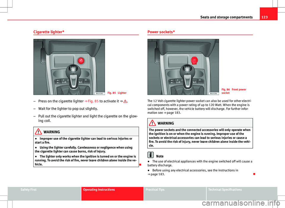
Fig. 85 Lighter
– Press on the cigarette lighter ⇒ Fig. 85 to activate it ⇒
.
– Wait for the lighter to pop out slightly.
– Pull out the cigarette lighter and light the cigarette on the glow-
ing coil.
WARNING
● Improper use of the cigarette lighter can lead to serious injuries or
start a fire.
● Using the lighter carefully. Carelessness or negligence when using
the cigarette lighter can cause burns, risk of injury.
● The lighter only works when the ignition is turned on or the engine is
running. To avoid the risk of fire, never leave children alone inside the ve-
hicle.
Power sockets*
Fig. 86 Front power
socket
The 12 Volt cigarette lighter power socket can also be used for other electri-
cal components with a power rating of up to 120 Watt. When the engine is
switched off, however, the vehicle battery will discharge. For further infor-
mation see ⇒ page 183.
WARNING
The power sockets and the connected accessories will only operate when
the ignition is on or when the engine is running. Improper use of the
sockets or electrical accessories can lead to serious injuries or cause a
fire. To avoid the risk of injury, never leave children alone inside the vehi-
cle.
Note
● The use of electrical appliances with the engine switched off will cause a
battery discharge.
● Before using any electrical accessories, see the instructions in
⇒ page 183.
Safety FirstOperating InstructionsPractical TipsTechnical Specifications
Page 127 of 280
125
Seats and storage compartments
Luggage compartment
Storing objects
All luggage must be securely stowed. Please observe the following points to ensure the vehicle handles
well at all times:
– Distribute the load as evenly as possible.
– Place heavy objects as far forward in the luggage compartment
as possible.
WARNING
● Loose luggage and other loose items in the vehicle may cause serious
injuries.
● Loose objects in the luggage compartment can suddenly move and
change the way the vehicle handles.
● In case of sudden manoeuvres or accidents, loose objects in the inte-
rior can be flung forward, injuring passengers.
● Always put objects in the luggage compartment.
● When you transport heavy objects, always take into account that a
change in the centre of gravity can also cause changes in vehicle han-
dling.
● Please observe information on safe driving ⇒ page 7, Safe driving.
CAUTION
Hard objects on the rear shelf could chafe against the wires of the heating
element in the heated rear window and cause damage.
Note
The ventilation slots in front of the rear side windows must not be covered
as this would prevent stale air being extracted from the vehicle.
Rear shelf
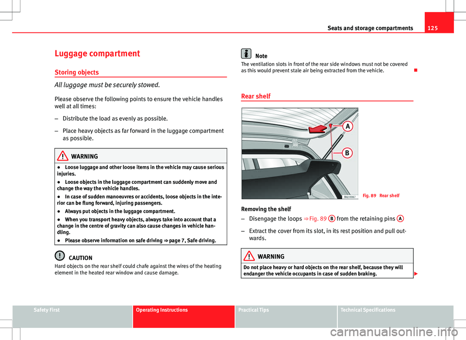
Fig. 89 Rear shelf
Removing the shelf
– Disengage the loops ⇒
Fig. 89 B
from the retaining pins A
–
Extract the cover from its slot, in its rest position and pull out-
wards.
WARNING
Do not place heavy or hard objects on the rear shelf, because they will
endanger the vehicle occupants in case of sudden braking.
Safety FirstOperating InstructionsPractical TipsTechnical Specifications
Page 129 of 280
127
Air conditioning
Air conditioning Heating
Controls
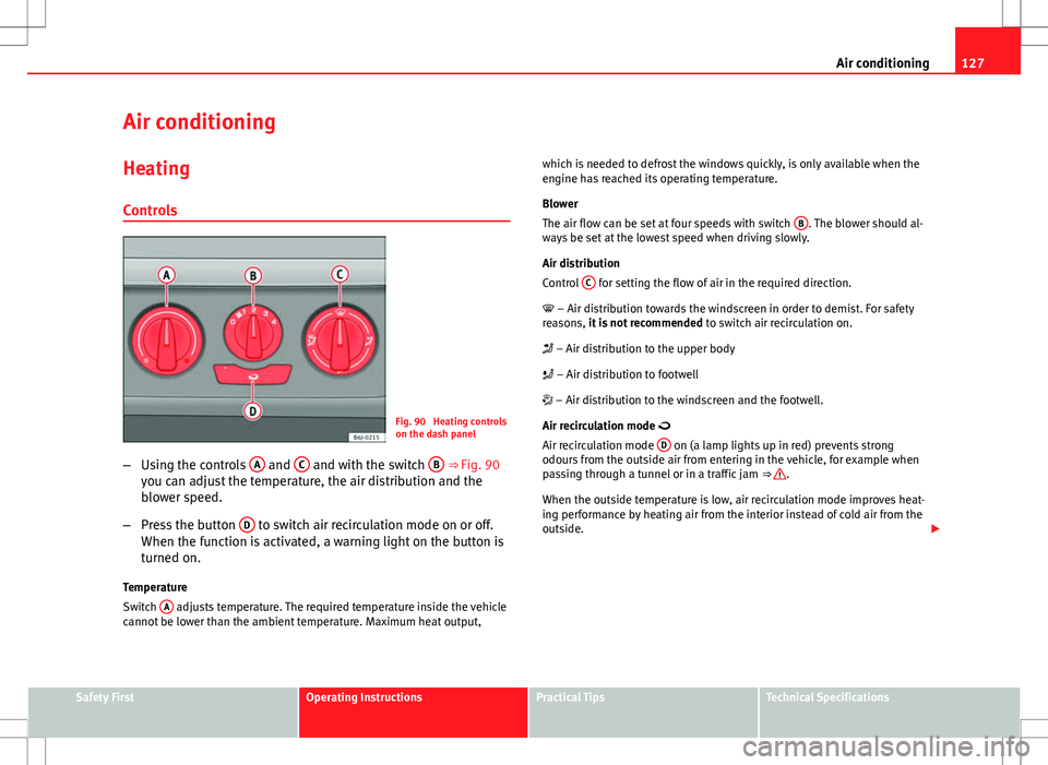
Fig. 90 Heating controls
on the dash panel
– Using the controls A
and C and with the switch B ⇒ Fig. 90
you can adjust the temperature, the air distribution and the
blower speed.
– Press the button D
to switch air recirculation mode on or off.
When the function is activated, a warning light on the button is
turned on.
Temperature
Switch A
adjusts temperature. The required temperature inside the vehicle
cannot be lower than the ambient temperature. Maximum heat output, which is needed to defrost the windows quickly, is only available when the
engine has reached its operating temperature.
Blower
The air flow can be set at four speeds with switch
B
. The blower should al-
ways be set at the lowest speed when driving slowly.
Air distribution
Control C
for setting the flow of air in the required direction.
– Air distribution towards the windscreen in order to demist. For safety
reasons, it is not recommended to switch air recirculation on.
– Air distribution to the upper body
– Air distribution to footwell
– Air distribution to the windscreen and the footwell.
Air recirculation mode
Air recirculation mode D
on (a lamp lights up in red) prevents strong
odours from the outside air from entering in the vehicle, for example when
passing through a tunnel or in a traffic jam ⇒
.
When the outside temperature is low, air recirculation mode improves heat-
ing performance by heating air from the interior instead of cold air from the
outside.
Safety FirstOperating InstructionsPractical TipsTechnical Specifications
Page 131 of 280
129
Air conditioning
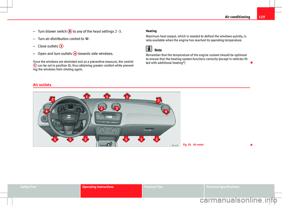
– Turn blower switch B
to any of the head settings 2 -3.
– Turn air distribution control to .
– Close outlets 3
–
Open and turn outlets 4 towards side windows.
Once the windows are demisted and as a preventive measure, the control C
can be set in position , thus obtaining greater comfort while prevent-
ing the windows from misting again. Heating
Maximum heat output, which is needed to defrost the windows quickly, is
only available when the engine has reached its operating temperature.
Note
Remember that the temperature of the engine coolant should be optimum
to ensure that the heating system functions correctly (except in vehicles fit-
ted with additional heating*)
Air outlets
Fig. 92 Air vents
Safety FirstOperating InstructionsPractical TipsTechnical Specifications
Page 133 of 280
131
Air conditioning
WARNING
For your safety, the windows should never be fogged up or covered with
snow or ice. This is essential to ensure good visibility. Please familiarise
yourself with the correct operation of the heating and ventilation system,
including the demist/defrost functions for the windows.
Note
Please consider the general notes.
Vehicle interior heating or cooling system
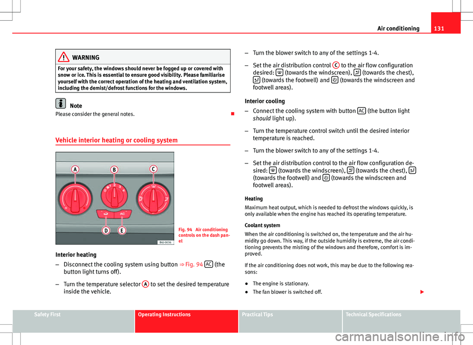
Fig. 94 Air conditioning
controls on the dash pan-
el
Interior heating
– Disconnect the cooling system using button ⇒ Fig. 94 AC
(the
button light turns off).
– Turn the temperature selector A
to set the desired temperature
inside the vehicle. –
Turn the blower switch to any of the settings 1-4.
– Set the air distribution control C
to the air flow configuration
desired: (towards the windscreen), (towards the chest),
(towards the footwell) and (towards the windscreen and
footwell areas).
Interior cooling
– Connect the cooling system with button AC
(the button light
should light up).
– Turn the temperature control switch until the desired interior
temperature is reached.
– Turn the blower switch to any of the settings 1-4.
– Set the air distribution control to the air flow configuration de-
sired:
(towards the windscreen), (towards the chest), (towards the footwell) and (towards the windscreen and
footwell areas).
Heating
Maximum heat output, which is needed to defrost the windows quickly, is
only available when the engine has reached its operating temperature.
Coolant system
When the air conditioning is switched on, the temperature and the air hu-
midity go down. This way, if the outside humidity is extreme, the air condi-
tioning prevents the misting of the windows and therefore, comfort is im-
proved.
If the air conditioning does not work, this may be due to the following rea-
sons:
● The engine is stationary.
● The fan blower is switched off.
Safety FirstOperating InstructionsPractical TipsTechnical Specifications
Page 135 of 280
133
Air conditioning
Climatronic Controls
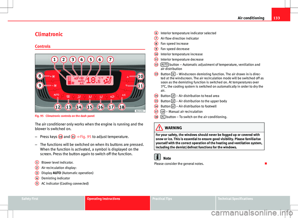
Fig. 95 Climatronic controls on the dash panelThe air conditioner only works when the engine is running and the
blower is switched on.
– Press keys 10
and 11 ⇒ Fig. 95 to adjust temperature.
– The functions will be switched on when its buttons are pressed.
When the function is activated, a symbol is displayed on the
screen. Press the button again to switch off the function.
Blower level indicator.
Air recirculation display:
Display AUTO (Automatic operation)
Demisting indicator
AC indicator (Cooling connected)
1
2345
Interior temperature indicator selected
Air flow direction indicator
Fan speed increase
Fan speed decrease
Interior temperature increase
Interior temperature decrease
AUTO
button – Automatic adjustment of temperature, ventilation and
air distribution
Button
– Windscreen demisting function. The air drawn in is direc-
ted at the windscreen. The air recirculation mode will be switched off as
soon as the demisting function is switched on. At temperatures over
3°C, the cooling system is switched on automatically in order to dry the
air.
Button
– Air distribution to head area
Button – Air distribution to the upper body
Button – Air distribution to footwell
– Manual air recirculation
AC button – To switch on the air conditioning.
WARNING
For your safety, the windows should never be fogged up or covered with
snow or ice. This is essential to ensure good visibility. Please familiarise
yourself with the correct operation of the heating and ventilation system,
including the demist/defrost functions for the windows.
Note
Please consider the general notes.
6
789101112
13
1415161718
Safety FirstOperating InstructionsPractical TipsTechnical Specifications
Page 137 of 280
135
Air conditioning
Air recirculation mode
Air recirculation mode prevents fumes or unpleasant smells
from coming from the outside. – Press the button
to switch air recirculation mode on or off.
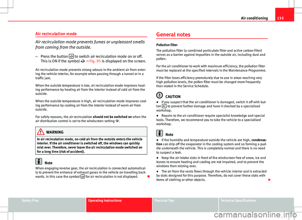
This is ON if the symbol ⇒ Fig. 95 is displayed on the screen.
Air recirculation mode prevents strong odours in the ambient air from enter-
ing the vehicle interior, for example when passing through a tunnel or in a
traffic jam.
When the outside temperature is low, air recirculation mode improves heat-
ing performance by heating air from the interior instead of cold air from the
outside.
When the outside temperature is high, air recirculation mode improves cool-
ing performance by cooling air from the interior instead of warm air from
outside.
For safety reasons, the air recirculation should not be switched on when the
air distribution control is set to the windscreen setting .
WARNING
In air recirculation mode, no cold air from the outside enters the vehicle
interior. If the air conditioner is switched off, the windows can quickly
mist over. Therefore, never leave the air recirculation mode switched on
for a long time (risk of accident).
Note
When engaging reverse gear, the air recirculation is connected automatical-
ly to prevent the entrance of exhaust gases in the vehicle on travelling back-
wards. In this case the symbol
for air recirculation is not displayed. General notes
Pollution filter
The pollution filter (a combined particulate filter and active carbon filter)
serves as a barrier against impurities in the outside air, including dust and
pollen.
For the air conditioner to work with maximum efficiency, the pollution filter
must be replaced at the specified intervals in the Maintenance Programme.
If the filter loses efficiency prematurely due to use in areas reaching very
high pollution levels, the pollen filter must be changed more frequently
than stated in the Service Schedule.
CAUTION
● If you suspect that the air conditioner is damaged, switch it off with but-
ton AC
to prevent further damage and have it checked by a specialised
workshop.
● Repairs to the air conditioner require specialist knowledge and special
tools. Therefore, we recommend you to take the vehicle to a specialised
workshop.
Note
● If the humidity and temperature outside the vehicle are high, condensa-
tion can drip off the evaporator in the cooling system and so forming a pud-
dle underneath the vehicle. This is completely normal and there is no need
to suspect a leak.
● Keep the air intake slots in front of the windscreen free of snow, ice and
leaves to ensure heating and cooling are not impaired, and to prevent the
windows from misting over.
● The air from the vents flows through the vehicle interior and is extracted
by slots designed for this purpose. Therefore, do not cover these slots with
items of clothing or other objects.
Safety FirstOperating InstructionsPractical TipsTechnical Specifications
Page 139 of 280
137
Driving
Driving SteeringAdjusting the steering wheel position
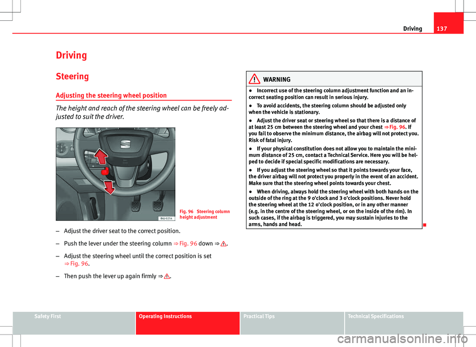
The height and reach of the steering wheel can be freely ad-
justed to suit the driver.
Fig. 96 Steering column
height adjustment
– Adjust the driver seat to the correct position.
– Push the lever under the steering column ⇒ Fig. 96 down ⇒
.
– Adjust the steering wheel until the correct position is set
⇒ Fig. 96.
– Then push the lever up again firmly ⇒
.
WARNING
● Incorrect use of the steering column adjustment function and an in-
correct seating position can result in serious injury.
● To avoid accidents, the steering column should be adjusted only
when the vehicle is stationary.
● Adjust the driver seat or steering wheel so that there is a distance of
at least 25 cm between the steering wheel and your chest ⇒ Fig. 96. If
you fail to observe the minimum distance, the airbag will not protect you.
Risk of fatal injury.
● If your physical constitution does not allow you to maintain the mini-
mum distance of 25 cm, contact a Technical Service. Here you will be hel-
ped to decide if special specific modifications are necessary.
● If you adjust the steering wheel so that it points towards your face,
the driver airbag will not protect you properly in the event of an accident.
Make sure that the steering wheel points towards your chest.
● When driving, always hold the steering wheel with both hands on the
outside of the ring at the 9 o'clock and 3 o'clock positions. Never hold
the steering wheel at the 12 o'clock position, or in any other manner
(e.g. in the centre of the steering wheel, or on the inside of the rim). In
such cases, if the airbag is triggered, you may sustain injuries to the
arms, hands and head.
Safety FirstOperating InstructionsPractical TipsTechnical Specifications
Page 141 of 280
139
Driving
Ignition switched off, steering lock 1
In this position
⇒ Fig. 98 the ignition and the engine are OFF and the steer-
ing may get locked.
For the Steering lock to operate without the ignition key, turn the steering
wheel until it locks with an audible sound. You should always lock the steer-
ing wheel when you leave your vehicle. This will help prevent vehicle theft
⇒
.
Switching the ignition or the glow plug system on 2
Turn the ignition key to this position and release it. If the key cannot be
turned or it is difficult to turn from position 1 to position 2, move the
steering wheel from one side to the other until it is released.
Starting 3
The engine is started when the key is in this position. Electrical components
with a high power consumption are switched off temporarily.
Every time the vehicle is started again, the ignition key must be turned to
position 1
. The
repetitive start prevention lock of the ignition prevents
possible damage to the starter motor if the engine is already running.
WARNING
● The ignition key must NOT be removed from the lock until the vehicle
comes to a standstill. Otherwise, the steering could be immediately
blocked- Risk of accident!
● Always remove the key from the ignition when leaving the vehicle,
even for a short period. This is especially important if children or disa-
bled people are left alone in the vehicle. They could accidentally start the
engine or work electrical equipment such as the electric windows, conse-
quently resulting in an accident.
● Unsupervised use of the keys could start the engine or any electrical
system, such as the electric window. This could result in serious injury.
CAUTION
The starter motor will only work when the engine is stopped (ignition key
position 3
).
Electronic immobiliser
The electronic immobiliser prevents unauthorised persons
from driving the vehicle.
Inside the key there is a chip that deactivates the electronic immobiliser au-
tomatically when the key is inserted into the ignition.
The electronic immobiliser will be activated again automatically as soon as
you pull the key out of the ignition lock.
The engine can only be started using a genuine SEAT key with its correct
code.
Note
A perfect operation of the vehicle is ensured if genuine SEAT keys are used.
Safety FirstOperating InstructionsPractical TipsTechnical Specifications
Page 143 of 280
141
Driving
Starting diesel engines
The engine can only be started using a genuine SEAT key
with its correct code. – Move the gearbox lever to the neutral position and depress the
clutch pedal thoroughly and hold it in this position for the start-
er to turn the engine on.
– Turn the ignition key to the starting position.
– Turn the ignition key to position ⇒ Fig. 98 2
. The warning lamp
will light for engine pre-heating.
– When the lamp turns off, turn the ignition key to position 3
to
start the engine. Do not press the accelerator.
– Let go of the ignition key as soon as the engine starts, the start-
er motor must not be allowed to run on with the engine.
When starting a very cold engine, it may be a little noisy for the first few sec-
onds until oil pressure has built up in the hydraulic valve compensators.
This is quite normal, and no cause for concern.
If there are problems starting the engine, see the ⇒ page 241.
Glow plug system for the diesel engine
To avoid unnecessary discharging of the battery, do not use any other major
electrical equipment while the glow plugs are pre-heating.
Start the engine as soon as the glow plug warning lamp goes out.
Starting the diesel engine after the fuel tank has been completely run dry
If the fuel tank has been completely run dry, it may take longer than normal
(up to one minute) to start a diesel engine after refuelling. This is because
the fuel system must eliminate air first.
WARNING
● Never start or run the engine in unventilated or closed rooms. The ex-
haust gases contain carbon monoxide, an odourless and colourless poi-
sonous gas. Risk of fatal accidents. Carbon monoxide can cause loss of
consciousness. It can also result in death.
● Never leave the vehicle unattended if the engine is running.
● Never use “cold start sprays”, they could explode or cause the engine
to run at high revs. Risk of injury.
CAUTION
● When the engine is cold, you should avoid high engine speeds, driving
at full throttle and over-loading the engine. Risk of engine damage.
● The vehicle should not be pushed or towed more than 50 metres to start
the engine. Unburnt fuel could enter the catalytic converter and damage it.
● Before attempting to push-start or tow a vehicle in order to start it, you
should first try to start it using the battery of another vehicle. Note and fol-
low the instructions in ⇒ page 241, Jump-starting.
For the sake of the environment
Do not warm-up the engine by running the engine with the vehicle station-
ary. You should drive off as soon as you start the engine. This helps the en-
gine reach operating temperature faster and reduces emissions.
Switching off the engine
– Stop the vehicle.
– Turn the ignition key to position ⇒ Fig. 98 1
.
After switching the engine off, the radiator fan may run on for up to 10 mi-
nutes. It is also possible that the fan turns itself on once more if the coolant
Safety FirstOperating InstructionsPractical TipsTechnical Specifications