engine Seat Ibiza SC 2015 Owner's Guide
[x] Cancel search | Manufacturer: SEAT, Model Year: 2015, Model line: Ibiza SC, Model: Seat Ibiza SC 2015Pages: 248, PDF Size: 4.77 MB
Page 102 of 248
Operation
●
Addition a
l lights and other accessories in
front of the air inlet reduce the cooling effect
of the coolant. At high outside temperatures
and high engine loads, there is a risk of the
engine overheating.
● The front spoiler also ensures proper distri-
bution of the c
ooling air when the vehicle is
moving. If the spoiler is damaged this can re-
duce the cooling effect, which could cause
the engine to overheat. Seek specialist assis-
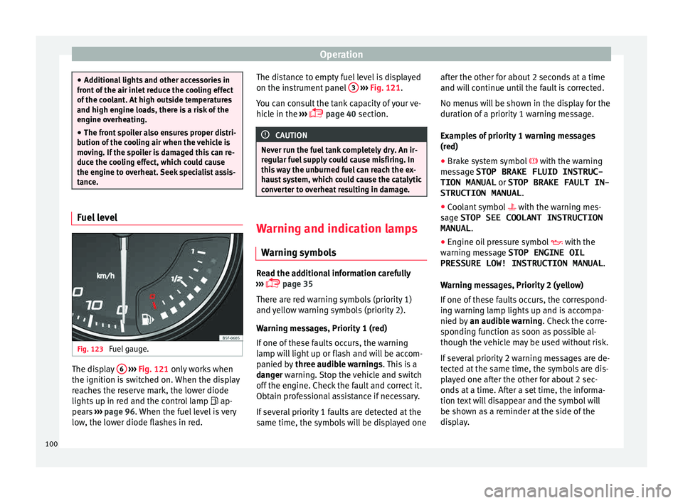
tance. Fuel level
Fig. 123
Fuel gauge. The display
6
› ›
› Fig. 121
only works when
the ignition is switched on. When the display
reaches the reserve mark, the lower diode
lights up in red and the control lamp ap-
pears ››› page 96. When the fuel level is very
low, the lower diode flashes in red. The distance to empty fuel level is displayed
on the instrument
panel 3
› ››
Fig. 121
.
Y
ou can consult the tank capacity of your ve-
hicle in the ›››
page 40 section. CAUTION
Never run the fuel tank completely dry. An ir-
re gu
lar fuel supply could cause misfiring. In
this way the unburned fuel can reach the ex-
haust system, which could cause the catalytic
converter to overheat resulting in damage. Warning and indication lamps
W arnin
g symbo
ls Read the additional information carefully
› ›
›
page 35
There are red warning symbols (priority 1)
and yellow warning symbols (priority 2).
Warning messages, Priority 1 (red)
If one of these faults occurs, the warning
lamp will light up or flash and will be accom-
panied by three audible warnings. This is a
danger warning. Stop the vehicle and switch
off the engine. Check the fault and correct it.
Obtain professional assistance if necessary.
If several priority 1 faults are detected at the
same time, the symbols will be displayed one after the other for about 2 seconds at a time
and wil
l continue until the fault is corrected.
No menus will be shown in the display for the
duration of a priority 1 warning message.
Examples of priority 1 warning messages
(red)
● Brake system symbol with the warnin
g
message STOP BRAKE FLUID INSTRUC-
TION MANUAL or STOP BRAKE FAULT IN-
STRUCTION MANUAL .
● Coolant symbol with the warnin
g mes-
sage STOP SEE COOLANT INSTRUCTION
MANUAL .
● Engine oil pressure symbol with the
warnin
g message STOP ENGINE OIL
PRESSURE LOW! INSTRUCTION MANUAL .
Warning messages, Priority 2 (yellow)
If one of these faults occurs, the correspond-
ing warning lamp lights up and is accompa-
nied by an audible warning. Check the corre-
sponding function as soon as possible al-
though the vehicle may be used without risk.
If several priority 2 warning messages are de-
tected at the same time, the symbols are dis-
played one after the other for about 2 sec-
onds at a time. After a set time, the informa-
tion text will disappear and the symbol will
be shown as a reminder at the side of the
display.
100
Page 103 of 248
Instruments and warning/control lamps
Priority 2 warning messages will not be
sho wn u
ntil all Priority 1 warning messages
have been dealt with!
Examples of priority 2 warning reports (yel-
low):*
● Fuel warning light with the information text
PLEASE REFUEL .WARNING
If the warning lamps and messages are ignor-
ed, the v ehic
le may stall in traffic, or may
cause accidents and severe injuries.
● Never ignore the warning lamps or text
mess
ages.
● Stop the vehicle safely as soon as possible.
● Park the vehicle away from traffic and en-
sure th
at there are no highly flammable ma-
terials under the vehicle that could come into
contact with the exhaust system (e.g. dry
grass, fuel).
● A faulty vehicle represents a risk of acci-
dent for the driv
er and for other road users. If
necessary, switch on the hazard warning
lamps and put out the warning triangle to ad-
vise other drivers.
● Before opening the bonnet, switch off the
engine and al
low it to cool.
● In any vehicle, the engine compartment is a
hazar
dous area and could cause severe inju-
ries ››› page 201. CAUTION
Failure to heed the control lamps and text
mes s
ages when they appear may result in
faults in the vehicle. Engine management*
This warning lamp monitors the engine man-
agement
sy
stem for petrol engines.
The warning lamp (Electronic Power Con-
trol) lights up when the ignition is switched
on while system operation is being verified. It
should go out once the engine is started.
If there is a fault in the electronic engine
management system while you are driving,
this warning lamp will light up. Stop the vehi-
cle and seek technical assistance.
Engine pre-heating/fault system* The warning lamp lights up to show that the
glo
w p
lug
s are preheating the diesel engine.
The control lamp lights up
If the control lamp lights up when the en-
gine is started it means that the glow plugs
are preheating. When the warning lamp goes
off, the engine should be started straight
away. Control lamp
flashe
s
If a fault develops in the engine management
system while you are driving, the glow plug
system lamp will flash . Take the vehicle to
a specialised workshop as soon as possible
and have the engine checked.
Accumulation of soot in the diesel en-
gine partic
ulate filter* If the control lamp
lights up
y
ou should
help the filter clean itself by driving in the ap-
propriate manner.
To do this, drive about 15 minutes in fourth
or fifth gear (automatic gearbox: S gear
range) at a minimum speed of 60 km/h
(37 mph), with the engine running at approxi-
mately 2,000 rpm. In this way, the soot build
up in the filter is burned. When cleaning is
successful, the control lamp turns off.
If the lamp does not turn off, or the three
lamps turn on (particulate filter , fault in
the emission control system and glow
plugs ), drive the vehicle to a specialised
workshop and have the fault repaired at the
earliest opportunity. »
101
Technical data
Advice
Operation
Emergencies
Safety
Page 104 of 248
Operation
WARNING
● Alw a
ys drive according to the road weather
conditions, the terrain and traffic. Driving rec-
ommendations should never lead to illegal
manoeuvres in surrounding traffic.
● The diesel engine particulate filter may
reac
h extremely high temperatures; in this
case the vehicle should be parked so that it
does not enter into contact with highly flam-
mable materials underneath the vehicle. Oth-
erwise there is a risk of fire. Engine oil pressure
If this warning lamp
is
r
ed it indicates
that the engine oil pressure is too low.
If this warning symbol starts to flash, and is
accompanied by three audible warnings,
switch off the engine and check the oil level.
If necessary, add more oil ›››
page 206.
If the warning lamp flashes although the oil
level is correct, stop driving. Do not even run
the engine at idle speed! Obtain technical as-
sistance.
Checking the oil level
If the warning lamp is yellow the engine
oil level should be checked as soon as possi-
ble. Top up the oil ›››
page 206 at the next
opportunity. Oil level sensor faulty*
If the
y
ellow warning lamp flashes, take
the vehicle to a specialised workshop to have
the oil level sensor checked. Until then it is
advisable to check the oil level every time
you refuel.
Lamp fault* The warning lamp lights up when there is
a f
au
lt on the turn signals, headlights, side
lights and fog lights.
Windscreen washer fluid* This warning lamp lights up to indicate that
the w
ind
s
creen washer level is very low.
This serves as a reminder to fill up the reser-
voir at the earliest opportunity ›››
page 209.
Rear fog light* The warning lamp lights
up when the r
e
ar
fog light is switched on. For further informa-
tion see ›››
page 123. Anti-lock brake system (ABS)* The control lamp
lights up for a f
ew sec-
onds when the ignition is switched on. It
goes out again after the system has run
through an automatic test sequence.
There is a fault in the ABS if:
● The control lamp does not
light up when
the ignition is switched on.
● The control lamp does not go out again af-
ter a few sec
onds.
● The control lamp lights up when the vehicle
is mo
ving.
The vehicle can still be braked in the normal
way, without the ABS function. Take the vehi-
cle to a specialised workshop as soon as
possible. For further information on the ABS
see the ›››
page 171.
If there is a fault in the ABS, the ESC* and the
tyre pressure control lamp will also light up.
Brake system fault
If the ABS warning lamp lights up together
with the brake warning lamp , there is a
fault in the ABS function and in the brake
system ››› .
102
Page 105 of 248
Instruments and warning/control lamps
WARNING
● Bef or
e opening the bonnet, read and ob-
serve the warnings ››› page 201, Working in
the engine compartment.
● If the brake system warning lamp should
light
up together with the ABS warning lamp
, stop the vehicle immediately and check
the brake fluid level in the reservoir
››› page 208, Brake fluid. If the brake fluid
level has dropped below the “MIN” mark you
must not drive on. Risk of accident. Obtain
technical assistance.
● If the brake fluid level is correct, the fault in
the brake sy
stem may have been caused by a
failure of the ABS system. This could cause
the rear wheels to lock quickly when you
brake. This could cause the rear to break
away. Risk of skidding. Stop the vehicle and
seek technical assistance. Differential lock fault (EDS)*
The EDL operates along with the ABS in vehi-
c
l
e
s equipped with Electronic Stability Con-
trol (ESC)*.
A malfunction in the EDL is indicated by the
ABS control lamp . Take the vehicle to a
specialised workshop as soon as possible.
For further information on the EDL see
››› page 170, Electronic differential lock
(EDS)*. Traction control system (ASR)* / The traction control system prevents the driv-
en wheels
fr
om spinning when the vehicle is
accelerating.
There are two control lamps for the traction
control system: and . Both control lamps
light up together when the ignition is switch-
ed on and should turn off after approximately
2 seconds. This is the time taken for the func-
tion check.
The lamp has the following function:
● It flashes when the ASR is working if the ve-
hicl e i
s moving.
If the system is deactivated or if it has any
fault, the warning lamp will remain lit. The
warning lamp will also light up if a fault
should occur in the ABS because the ASR op-
erates in conjunction with the ABS. For fur-
ther information, see ›››
page 172.
The lamp provides information about the
disconnection status of the system:
● It stays lit when the ASR is disconnected
via E
asy Connect.
By means of Easy Connect, the ASR function
is reactivated and the warning lamp switched
off. Electronic Stability Control (ESC)*
/ There are two control lamps for the electronic
st
ab
ility control. The lamp provides infor-
mation concerning function and disconnec-
tion status.
Both control lamps light up together when
the ignition is switched on and should turn
off after approximately 2 seconds. This is the
time taken for the function check.
This programme includes the ABS, EDL and
ASR. It also includes emergency braking as-
sistance (BAS).
The control lamp has the following func-
tions:
● It flashes whilst driving when the ASR/ESC
is activ
ated.
● It will light up if there is a fault in the ESC.
● As the ESC operates in conjunction with the
ABS, the ESC light
will also come on if a fault
should occur in the ABS.
If the ESC control lamp lights up and stays
on after the engine is started, this may mean
that the control system has temporarily
switched off the ESC. In this case the ESC can
be reactivated by switching the ignition off
and then on again. If the control lamp goes
out, this means the system is fully functional. »
103
Technical data
Advice
Operation
Emergencies
Safety
Page 107 of 248
Instruments and warning/control lamps
WARNING
● When the tyr e pr
essure control lamp lights
up, reduce speed immediately and avoid any
sudden turning or braking manoeuvre. Stop
when possible, and check the tyre pressure
and status.
● The driver is responsible for maintaining
correct
tyre pressures. For this reason, tyre
pressure must be regularly checked.
● Under certain circumstances (e.g. when
driving in a s
porty manner, in winter condi-
tions or on a dirt track) the tyre control lamp
may light up belatedly or may function incor-
rectly. Note
If the battery is disconnected, the yellow
warnin g l
amp lights up after turning the
ignition on. This should turn off after a brief
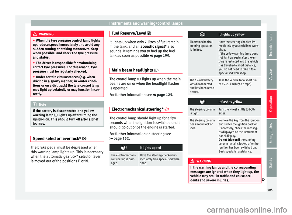
journey. Speed selector lever lock*
The brake pedal must be depressed when
thi
s
w
arning lamp lights up. This is necessary
when the automatic gearbox* selector lever
is moved out of the positions P or N.Fuel Reserve/Level
It lights up when only 7 litres of fuel remain
in the tank, and an
ac
oustic signal* also
sounds. It reminds you to fuel up the fuel
tank as soon as possible ››› page 199.
Main beam headlights The control lamp
lights up when the m ain
be
ams are on or when the headlight flasher
is operated.
For further information see ›››
page 125.
Electromechanical steering* The control lamp should light up for a few
sec
ond
s
when the ignition is switched on. It
should go out once the engine is started.
For further information on steering see
››› page 152.
It lights up red
The electromechani-
cal steering is dam-
aged.Have the steering checked im-
mediately by a specialised work-
shop.
It lights up yellow
Electromechanical
steering operation
is limited.Have the steering checked im-
mediately by a specialised work-
shop.
If the yellow warning lamp does
not light up again after the en-
gine is restarted and the vehicle
has travelled a short distance,
you do not need to take it to a
specialised workshop.
The 12-volt battery
was disconnected
and has been recon-
nected.Take the vehicle for a short run
at 15-20 km/h (9-12 mph).
It flashes yellow
The steering column
is tight.Turn the wheel a little to both
sides.
The steering column
does not unlock or
lock.Remove the key from the ignition
and switch the ignition back on.
If necessary, check the messag-
es displayed on the instrument
panel display.
Do not drive on if
the steering
column remains locked after the
ignition has been switched on.
Seek specialist assistance. WARNING
If the warning lamps and the corresponding
mes s
ages are ignored when they light up, the
vehicle may stall in traffic and cause acci-
dents and severe injuries. » 105
Technical data
Advice
Operation
Emergencies
Safety
Page 108 of 248
Operation
●
Never ignor e the w
arning lamps or messag-
es.
● Stop the vehicle at the next opportunity
and in a safe p
lace. Note
Failure to heed the control lamps and corre-
s pondin g t
ext messages when they light up
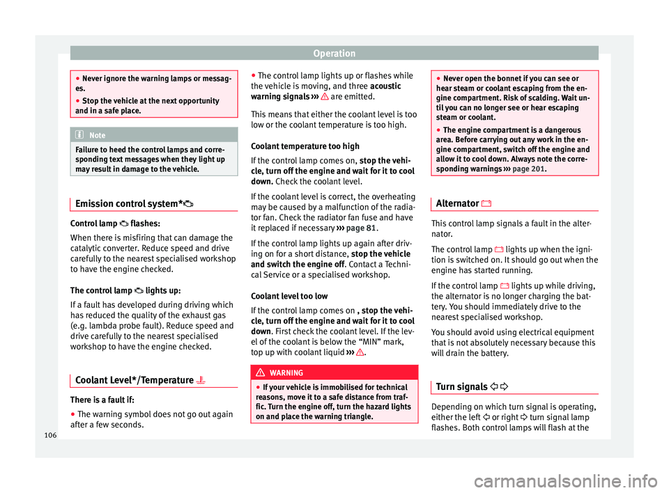
may result in damage to the vehicle. Emission control system*
Control lamp
fla
she
s:
When there is misfiring that can damage the
catalytic converter. Reduce speed and drive
carefully to the nearest specialised workshop
to have the engine checked.
The control lamp lights up:
If a fault has developed during driving which
has reduced the quality of the exhaust gas
(e.g. lambda probe fault). Reduce speed and
drive carefully to the nearest specialised
workshop to have the engine checked.
Coolant Level*/Temperature There is a fault if:
● The warning symbol does not go out again
af t
er a f
ew seconds. ●
The contro
l lamp lights up or flashes while
the vehicle is moving, and three acoustic
warning signals ››› are emitted.
Thi s
me
ans that either the coolant level is too
low or the coolant temperature is too high.
Coolant temperature too high
If the control lamp comes on, stop the vehi-
cle, turn off the engine and wait for it to cool
down. Check the coolant level.
If the coolant level is correct, the overheating
may be caused by a malfunction of the radia-
tor fan. Check the radiator fan fuse and have
it replaced if necessary ››› page 81.
If the control lamp lights up again after driv-
ing on for a short distance, stop the vehicle
and switch the engine off. Contact a Techni-
cal Service or a specialised workshop.
Coolant level too low
If the control lamp comes on , stop the vehi-
cle, turn off the engine and wait for it to cool
down. First check the coolant level. If the lev-
el of the coolant is below the “MIN” mark,
top up with coolant liquid ››› .
WARNING
● If y
our vehicle is immobilised for technical
reasons, move it to a safe distance from traf-
fic. Turn the engine off, turn the hazard lights
on and place the warning triangle. ●
Never open the bonnet if
you can see or
hear steam or coolant escaping from the en-
gine compartment. Risk of scalding. Wait un-
til you can no longer see or hear escaping
steam or coolant.
● The engine compartment is a dangerous
area. B
efore carrying out any work in the en-
gine compartment, switch off the engine and
allow it to cool down. Always note the corre-
sponding warnings ››› page 201. Alternator
This control lamp signals a fault in the alter-
n
at
or
.
The control lamp lights up when the igni-
tion is switched on. It should go out when the
engine has started running.
If the control lamp lights up while driving,
the alternator is no longer charging the bat-
tery. You should immediately drive to the
nearest specialised workshop.
You should avoid using electrical equipment
that is not absolutely necessary because this
will drain the battery.
Turn signals Depending on which turn signal is operating,
either the l
ef
t
or right turn signal lamp
flashes. Both control lamps will flash at the
106
Page 109 of 248
Introduction to the Easy Connect system*
same time when the hazard warning lights
ar e sw
it
ched on.
If any of both turn signals fails, the warning
lamp will start flashing twice faster than nor-
mal.
For further information on the turn signals,
please see ››› page 125.
Electronic immobiliser “SAFE”* This warning lamp flashes if an unauthorised
k
ey
i
s used.
Inside the key there is a chip that deactivates
the electronic immobiliser automatically
when the key is inserted into the ignition.
The electronic immobiliser will be activated
again automatically as soon as you pull the
key out of the ignition lock.
If the following message* is shown on the in-
strument panel display: SAFE, the vehicle
cannot be started.
The engine can, however, be started if the
appropriate coded SEAT genuine key is used. Note
The vehicle cannot operate properly if you do
not h av
e a genuine SEAT key. Introduction to the Easy
C
onnect
sy
stem*
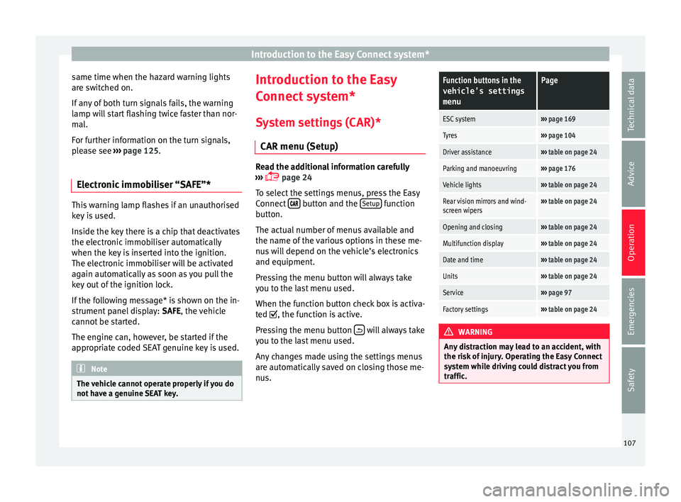
System settings (CAR)* CAR menu (Setup) Read the additional information carefully
›› ›
page 24
To select the settings menus, press the Easy
Connect button and the
Set
up function
b utt
on.
The act
ual number of menus available and
the name of the various options in these me-
nus will depend on the vehicle’s electronics
and equipment.
Pressing the menu button will always take
you to the last menu used.
When the function button check box is activa-
ted , the function is active.
Pressing the menu button will always take
y ou t
o the l
ast menu used.
Any changes made using the settings menus
are automatically saved on closing those me-
nus.
Function buttons in the vehicle’s settings
menuPage
ESC system››› page 169
Tyres››› page 104
Driver assistance››› table on page 24
Parking and manoeuvring››› page 176
Vehicle lights››› table on page 24
Rear vision mirrors and wind-
screen wipers››› table on page 24
Opening and closing››› table on page 24
Multifunction display››› table on page 24
Date and time››› table on page 24
Units››› table on page 24
Service››› page 97
Factory settings››› table on page 24 WARNING
Any distraction may lead to an accident, with
the risk of
injury. Operating the Easy Connect
system while driving could distract you from
traffic. 107
Technical data
Advice
Operation
Emergencies
Safety
Page 118 of 248
Operation
and clockwise for the right-hand side
door s.
D e
activating the childproof lock
– Unlock the vehicle and open the door
whose chi
ldproof lock you want to deacti-
vate.
– With the door open, rotate the groove in
the door usin
g the ignition key, anti-clock-
wise for the right-hand side doors, and
clockwise for the left-hand side doors
››› Fig. 129.
Once the childproof lock is activated, the
door can only be opened from the outside.
The childproof lock can be activated or deac-
tivated by inserting the key in the groove
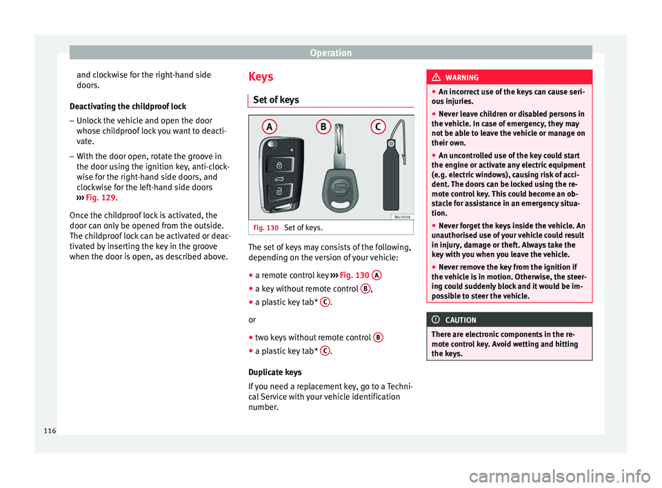
when the door is open, as described above. Keys
Set of k
eys Fig. 130
Set of keys. The set of keys may consists of the following,
dependin
g on the
v
ersion of your vehicle:
● a remote control key ›››
Fig. 130 A ●
a key without remote control B ,
● a plastic key tab* C .
or
● two keys without remote control B ●
a plastic key tab* C .
D up
lic
ate keys
If you need a replacement key, go to a Techni-
cal Service with your vehicle identification
number. WARNING
● An incorr ect
use of the keys can cause seri-
ous injuries.
● Never leave children or disabled persons in
the vehic
le. In case of emergency, they may
not be able to leave the vehicle or manage on
their own.
● An uncontrolled use of the key could start
the engine or activat
e any electric equipment
(e.g. electric windows), causing risk of acci-
dent. The doors can be locked using the re-
mote control key. This could become an ob-
stacle for assistance in an emergency situa-
tion.
● Never forget the keys inside the vehicle. An
unauthori
sed use of your vehicle could result
in injury, damage or theft. Always take the
key with you when you leave the vehicle.
● Never remove the key from the ignition if
the vehic
le is in motion. Otherwise, the steer-
ing could suddenly block and it would be im-
possible to steer the vehicle. CAUTION
There are electronic components in the re-
mote c ontr
ol key. Avoid wetting and hitting
the keys. 116
Page 125 of 248
Lights and visibility
●
Never c lo
se the tilting sunroof without first
checking that there are no obstructions. Risk
of serious injury to you or others. Make sure
that no one is in the path of the tilting sun-
roof.
● Always take the vehicle key with you when
you le
ave the vehicle.
● Never leave children or disabled persons in
the vehic
le, particularly if they have access to
the keys. Unsupervised use of a key could
mean that the engine is started or that elec-
trical equipment is used (e.g. electric tilting
sunroof) with a risk of accident. The doors
can be locked using the remote control key.
This could become an obstacle for assistance
in an emergency situation.
● The tilting sunroof continues to function
until
one of the front doors is opened and the
key removed from the ignition.
● Ensure that no object and/or end is be-
tween the gla
ss and the sunroof when the
one-touch opening/closing function is reset. Convenience closing*
Using the door lock
– Hold the key in the door lock of the driver
door in the loc k
in
g position until the tilting
sunroof is closed.
– Release the key to interrupt this function. Using the remote control
– Push the lock button on the remote control
for appr
oximately 3 seconds. The tilting
sunroof closes.
– Press the unlock button to interrupt the
function.
R
oll-back function of the tilting panor-
amic su
nroof* The tilting panoramic sunroof has a
ro
l
l-back
function which prevents larger objects get-
ting trapped when the roof is closed. The roll-
back function does not prevent fingers get-
ting pinched against the roof opening. The
tilting sunroof stops and opens again imme-
diately if it is obstructed when closing. Lights and visibility
Light s
Sw it
ching lights on and off Read the additional information carefully
›› ›
page 21
Switching on the front fog lights*
– Turn the switch from position or to
the firs
t stop and pull it. The symbol of
the light control lights up.
Switching on the rear fog light (vehicles with
front fog lights)
– Turn the lights control from position or
to the sec ond s
top and pull out ››› . A
c ontr
o
l lamp on the instrument panel lights
up.
Switching on the rear fog light (vehicles with
no front fog lights)
– Turn the light control to the end from posi-
tion or and pul
l it. A control lamp on
the instrument panel lights up. WARNING
Never drive with just the side lights on, there
is a ri
sk of accident. The side lights are not
bright enough to illuminate the road ahead » 123
Technical data
Advice
Operation
Emergencies
Safety
Page 136 of 248
Operation
– Mak
e s
ure that the head restraint engages
securely in one of its positions ››› page 60.
Removing the head restraint – Push the head restraint up as far as it will
go.
– Pr
ess the button ›››
Fig. 141 (arrow).
– Pull head restraint out of fitting without re-
lea
sing the button.
Fitting the head restraint
– Insert the head restraint into the guides on
the corre
sponding backrest.
– Push head restraint down.
– Adjust the head restraint to suit body size
›››
page 60. WARNING
● Never driv e if
the head restraints have been
removed. Risk of injury.
● Never drive if the head restraints are in an
uns
uitable position (the lowest position) as
there is a risk of serious injury.
● After refitting the head restraint, you must
alwa
ys adjust it properly for height to achieve
optimal protection.
● Please observe the safety warnings in ›››
in Correct adjustment of front head restraints
on pag
e 60
. Note
● To fit and r
emove the rear head restraints,
gently tilt the seat backrest forwards.
● When fitting the head restraints again, in-
sert the t
ubes as far as possible into the
guides without pressing the button. Seat functions
Heat ed se
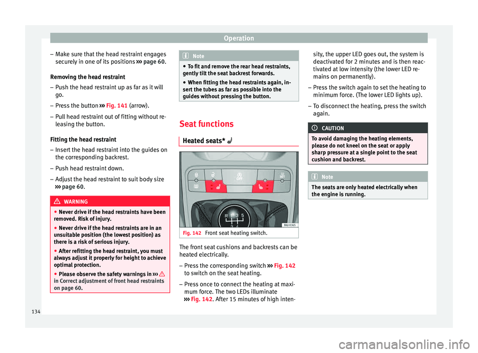
ats* Fig. 142
Front seat heating switch. The front seat cushions and backrests can be
he
at
ed el
ectrically.
– Press the corresponding switch ›››
Fig. 142
to switch on the seat heating.
– Press once to connect the heating at maxi-
mum forc
e. The two LEDs illuminate
››› Fig. 142. After 15 minutes of high inten- sity, the upper LED goes out, the system is
deactivat
ed for 2 minutes and is then reac-
tivated at low intensity (the lower LED re-
mains on permanently).
– Press the switch again to set the heating to
minimum forc
e. (The lower LED lights up).
– To disconnect the heating, press the switch
again. CAUTION
To avoid damaging the heating elements,
pl e
ase do not kneel on the seat or apply
sharp pressure at a single point to the seat
cushion and backrest. Note
The seats are only heated electrically when
the engine i s
running.134