gearbox Seat Ibiza ST 2016 User Guide
[x] Cancel search | Manufacturer: SEAT, Model Year: 2016, Model line: Ibiza ST, Model: Seat Ibiza ST 2016Pages: 252, PDF Size: 5.56 MB
Page 84 of 252
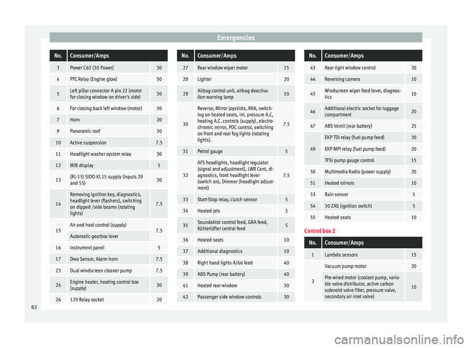
EmergenciesNo.Consumer/Amps
3Power C63 (30 Power)30
4PTC Relay (Engine glow)50
5Left pillar connector A pin 22 (motor
for closing window on driver's side)30
6For closing back left window (motor)30
7Horn20
9Panoramic roof30
10Active suspension7.5
11Headlight washer system relay30
12MIB display5
13(RL-15) SIDO Kl.15 supply (inputs 29
and 55)30
14
Removing ignition key, diagnostics,
headlight lever (flashers), switching
on dipped /side beams (rotating
lights)
7.5
15Air and heat control (supply)7.5Automatic gearbox lever
16Instrument panel5
17Dwa Sensor, Alarm horn7.5
23Dual windscreen cleaner pump7.5
24Engine heater, heating control box
(supply)30
2612V Relay socket20
No.Consumer/Amps
27Rear window wiper motor15
28Lighter20
29Airbag control unit, airbag deactiva-
tion warning lamp10
30
Reverse, Mirror joysticks, RKA, switch-
ing on heated seats, int. pressure A.C,
heating A.C. controls (supply), electro-
chromic mirror, PDC control, switching
on front and rear fog lights (rotating
lights).
7.5
31Petrol gauge5
32
AFS headlights, headlight regulator
(signal and adjustment), LWR Cent, di-
agnostics, front headlight lever
(switch on), Dimmer (headlight adjust-
ment)
7.5
33Start-Stop relay, clutch sensor5
34Heated jets5
35Soundaktor control feed, GRA feed,
Kühlerlüfter central feed5
36Heated seats10
37Additional diagnostics10
38Right hand lights A/66 feed40
39ABS Pump (rear battery)40
41Heated rear window30
42Passenger side window controls30
No.Consumer/Amps
43Rear right window control30
44Reversing camera10
45Windscreen wiper feed lever, diagnos-
tics10
46Additional electric socket for luggage
compartment20
47ABS Ventil (rear battery)25
49
EKP TDI relay (fuel pump feed)30
EKP MPI relay (fuel pump feed)20
TFSI pump gauge control15
50Multimedia Radio (power supply)20
51Heated mirrors10
53Rain sensor5
5430 ZAS (ignition switch)5
55Heated seats10
Control box 2
No.Consumer/Amps
1Lambda sensors15
2
Vacuum pump motor20
Pre-wired motor (coolant pump, varia-
ble valve distributor, active carbon
solenoid valve filter, pressure valve,
secondary air inlet valve)
10
82
Page 97 of 252
Controls and displays
Operation
C ontr
ol
s and displays
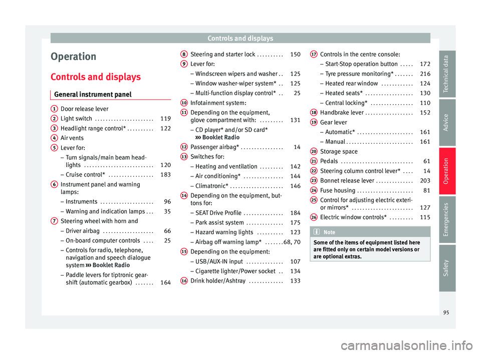
General instrument panel Door release lever
Light swit
c
h . . . . . . . . . . . . . . . . . . . . . . 119
Headlight range control* . . . . . . . . . .122
Air vents
Lever for:
– T
urn signals/main beam head-
lights . . . . . . . . . . . . . . . . . . . . . . . . . . 120
– Cruise c ontr
ol* . . . . . . . . . . . . . . . . . 183
Instrument panel and warning
lamps:
– Ins
truments . . . . . . . . . . . . . . . . . . . . 96
– Warning and indic ation l
amps . . . 35
Steering wheel with horn and – Driver airbag . . . . . . . . . . . . . . . . . . . 66
– On-board comp
uter controls . . . .25
– Control
s for radio, telephone,
navigation and speech dialogue
system ›››
Booklet Radio
– Paddle levers for tiptronic gear-
shift (automatic gearbox) . . . . . . .164
1 2
3
4
5
6
7 Steering and starter lock
. . . . . . . . . .150
Lever for: – Wind
sc
reen wipers and washer . .125
– Window wa
sher-wiper system* . .125
– Multi-fu
nction display control* . .25
Infotainment system:
Depending on the equipment,
glov
e compartment with: . . . . . . . . .131
– CD play
er* and/or SD card*
››› Booklet Radio
Passenger airbag* . . . . . . . . . . . . . . . . 14
Switches for:
– Heating and v
entilation . . . . . . . . . 142
– Air conditioning* . . . . . . . . . . . . . . . 144
– Clim
atronic* . . . . . . . . . . . . . . . . . . . . 146
D
epending on the equipment, but-
tons f
or:
– SEAT Drive Profile . . . . . . . . . . . . . . . 184
– Park a s
sist system . . . . . . . . . . . . . . 175
– Hazard warnin
g lights . . . . . . . . . . 123
– Airbag off warnin
g lamp* . . . . . . .68, 70
Depending on the equipment:
– USB/AUX-IN inp ut . . . . . . . . . . . . . . 107
– C
igar ett
e lighter/Power socket . .134
Drink holder/Ashtray . . . . . . . . . . . . .133
8 9
10
11
12
13
14
15
16 Controls in the centre console:
– St ar
t-
Stop operation button . . . . .172
– Tyre pr
essure monitoring* . . . . . . .216
– Heated re
ar window . . . . . . . . . . . . 124
– Heated seats* . . . . . . . . . . . . . . . . . . 130
– C
entral loc
king* . . . . . . . . . . . . . . . . 110
Handbrake lever . . . . . . . . . . . . . . . . . . 152
Gear lever – Automatic* . . . . . . . . . . . . . . . . . . . . . 161
– Manual . . . . . . . . . . . . . . . . . . . . . . . . . 161
St
orag
e space
Pedals . . . . . . . . . . . . . . . . . . . . . . . . . . . 61
St
eering column control lever* . . . .14
Bonnet release lever . . . . . . . . . . . . . .203
Fuse housing . . . . . . . . . . . . . . . . . . . . . 81
Control for adjusting electric exteri-
or mirrors* . . . . . . . . . . . . . . . . . . . . . . . 127
Electric
window controls* . . . . . . . . .115 Note
Some of the items of equipment listed here
are fitted on ly
on certain model versions or
are optional extras. 17
18
19
20
21
22
23
24
25
26
95
Technical data
Advice
Operation
Emergencies
Safety
Page 99 of 252
Instruments and warning/control lamps
CAUTION
● To prev ent
damage to the engine, the rev
counter needle should only remain in the red
zone for a short period of time.
● When the engine is cold, avoid high revs
and heavy acc
eleration and do not make the
engine work hard. For the sake of the environment
Changing up a gear in time reduces fuel con-
sumption and noise. Rev counter
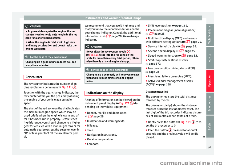
The rev counter indicates the number of en-
gine r
ev
olution
s per minute ›››
Fig. 121 1 .
T og
ether w ith the g
ear-change indicator, the
rev counter offers you the possibility of using
the engine of your vehicle at a suitable
speed.
The start of the red zone on the dial indicates
the maximum engine speed which may be
used briefly when the engine is warm and af-
ter it has been run in properly. Before reach-
ing this range, you should change to a higher
gear for vehicles with a manual gearbox or for
automatic gearboxes put the selector lever in
“D” or take your foot off the accelerator ped-
al. We recommend that you avoid high revs and
that y
ou follow the recommendations on the
gear-change indicator. Consult the additional
information in ›››
page 28, Gear-change
indicator. CAUTION
Never allow the rev counter needle 1 ›››
Fig. 121 to go int o the r
ed zone on the
scale for more than a very brief period, other-
wise there is a risk of engine damage. For the sake of the environment
Changing up a gear early will help you to save
fuel and minimi se emi
ssions and engine
noise. Indications on the display
A variety of information can be viewed on the
in
s
trument p
anel display ›››
Fig. 121 3 de-
pendin g on the
vehic
le equipment:
● Bonnet, rear lid and doors open
››› p
age 28.
● Information and warning texts.
● Mileage.
● Time.
● Navigation instructions.
● Outside temperature.
● Compass. ●
Shift lev
er position ››› page 161.
● Recommended gear (manual gearbox)
››› p
age 28.
● Multifunction display (MFD) and menus
with different
setting options ›››
page 25.
● Service interval display ›››
p
age 33.
● Second speed display ›››
p
age 25.
● Speed warning function ›››
p
age 32.
● Start-Stop system status display
››› p
age 172.
● Low consumption driving status (ECO)
››› p
age 98
● Identifying letters on engine (MKB).
● Active cylinder management display
(ACT ®
)* ›››
page 168
Distance travelled
The odometer registers the total distance
travelled by the car.
The odometer (trip ) shows the distance
travelled since the last odometer reset. The
last digit of the trip recorder indicates distan-
ces of 100 metres or one tenths of a mile.
● Briefly press the button ››› Fig. 121
4 to re-
set the trip r
ecor
der to 0.
● Keep the button 4 pressed for about 3
sec ond
s and the pr
evious value will be dis-
played. »
97
Technical data
Advice
Operation
Emergencies
Safety
Page 100 of 252
Operation
Time
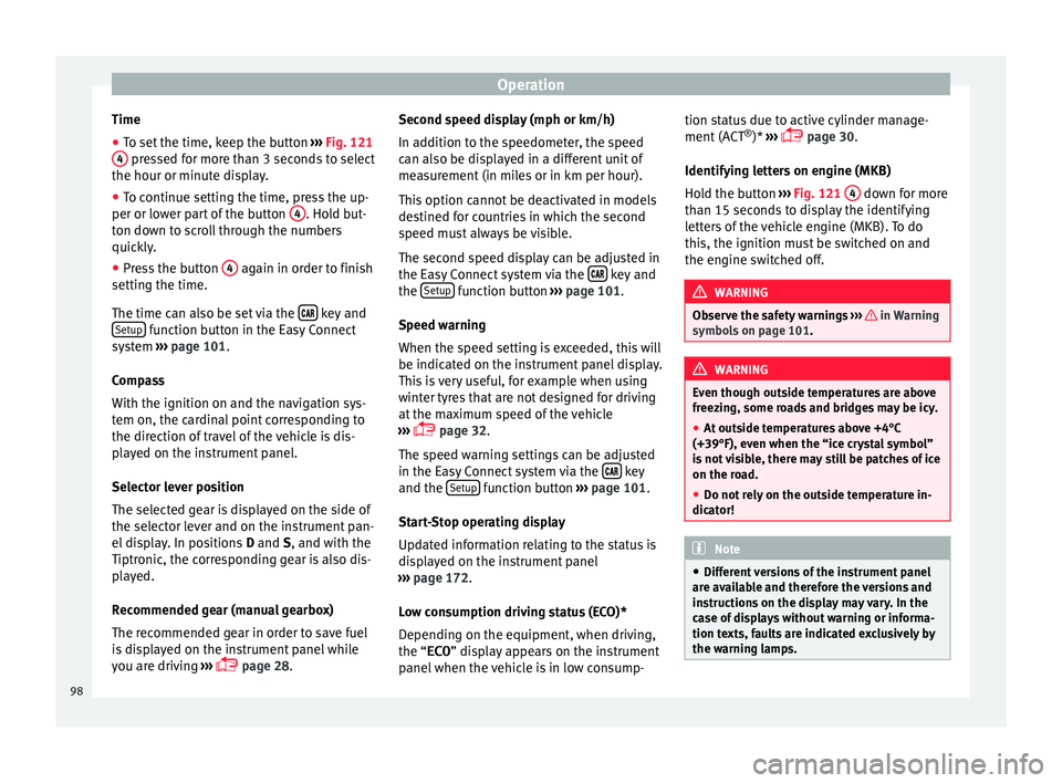
● To set the time, keep the button ››
›
Fig. 121
4 pressed for more than 3 seconds to select
the hour or minut e di
sp
lay.
● To continue setting the time, press the up-
per or lower par
t of the button 4 . Hold but-
t on do
wn to s
croll through the numbers
quickly.
● Press the button 4 again in order to finish
settin g the time.
The time c an also be set
via the key and
Set up function button in the Easy Connect
sy s
tem
›
›› page 101.
Compass
With the ignition on and the navigation sys-
tem on, the cardinal point corresponding to
the direction of travel of the vehicle is dis-
played on the instrument panel.
Selector lever position
The selected gear is displayed on the side of
the selector lever and on the instrument pan-
el display. In positions D and S, and with the
Tiptronic, the corresponding gear is also dis-
played.
Recommended gear (manual gearbox)
The recommended gear in order to save fuel
is displayed on the instrument panel while
you are driving ›››
page 28. Second speed display (mph or km/h)
In addition to the s
peedometer, the speed
can also be displayed in a different unit of
measurement (in miles or in km per hour).
This option cannot be deactivated in models
destined for countries in which the second
speed must always be visible.
The second speed display can be adjusted in
the Easy Connect system via the key and
the Set
up function button
››
›
p
age 101.
Speed warning
When the speed setting is exceeded, this will
be indicated on the instrument panel display.
This is very useful, for example when using
winter tyres that are not designed for driving
at the maximum speed of the vehicle
››› page 32.
The speed warning settings can be adjusted
in the Easy Connect system via the key
and the Set
up function button
››
›
p
age 101.
Start-Stop operating display
Updated information relating to the status is
displayed on the instrument panel
››› page 172.
Low consumption driving status (ECO)*
Depending on the equipment, when driving,
the “ECO ” display appears on the instrument
panel when the vehicle is in low consump- tion status due to active cylinder manage-
ment (ACT
®
)* ›
›› page 30.
Identifying letters on engine (MKB)
Hold the button ››› Fig. 121 4 down for more
th an 15 sec
onds
to display the identifying
letters of the vehicle engine (MKB). To do
this, the ignition must be switched on and
the engine switched off. WARNING
Observe the safety warnings ››› in Warning
symbols on p ag
e 101. WARNING
Even though outside temperatures are above
freezin g, some r
oads and bridges may be icy.
● At outside temperatures above +4°C
(+39°F), even when the “ice cr
ystal symbol”
is not visible, there may still be patches of ice
on the road.
● Do not rely on the outside temperature in-
dicator! Note
● Different
versions of the instrument panel
are available and therefore the versions and
instructions on the display may vary. In the
case of displays without warning or informa-
tion texts, faults are indicated exclusively by
the warning lamps. 98
Page 125 of 252
Lights and visibility
The instrument lighting (needles) is switched
on when the ignition i s
on and the light i
s
off. The instrument lighting is dimmed auto-
matically as the daylight starts to fade. It
goes out completely when ambient light is
very low. This function is intended to remind
the driver to switch on the dipped beam
headlights in good time when light condi-
tions become poor.
Headlight range control
By using the electrical headlight range con-
trol you can adjust the headlight range to the
load level that is being carried in the vehicle
››› Fig. 135. This way, it is possible to avoid
dazzling oncoming traffic more than necessa-
ry. At the same time, by using the correct
headlight settings, the driver has the best
possible lighting for the road ahead.
The headlights can only be adjusted when
the dipped beam is switched on. Turn the
wheel downwards to lower the headlight
beam from the basic setting 0.
Dynamic headlight range control
Vehicles with gas discharge bulbs (xenon
bulbs) are equipped with dynamic headlight
range control. When you switch on the lights,
their range regulates itself according to the
vehicle load.
Vehicles with gas discharge bulbs do not
have headlight range control. Hazard warning lights
Read the additional information carefully
›››
p
age 22
The hazard warning lights are used to draw
the attention of other road users to your vehi-
cle in emergencies.
If your vehicle breaks down:
1. Park your vehicle at a safe distance from moving tr
affic.
2. Press the button to switch on the hazard warning lights ›
›› .
3. Switch the ignition off.
4. Apply the handbrake.
5. For a manual gearbox, engage 1st gear; for an aut
omatic
gearbox, move the gear
lever to P.
6. Use the warning triangle to draw the atten- tion of other roa
d users to your vehicle.
7. Always take the vehicle key with you when you leav
e the vehicle.
All turn signals flash simultaneously when
the hazard warning lights are switched on.
The two turn signal turn signal lamps
and the turn signal lamp in the switch will
flash at the same time. The simultaneous
hazard warning lights also work when the ig-
nition is switched off. WARNING
● The risk of an ac
cident increases if your ve-
hicle breaks down. Always use the hazard
warning lights and a warning triangle to draw
the attention of other road users to your sta-
tionary vehicle.
● Due to the high temperatures that the cata-
lytic conv
erter can reach, never park in an
area where the catalytic converter could come
into contact with highly inflammable materi-
als, for example dry grass or spilt petrol. This
could start a fire. Note
● The batter y
will run down if the hazard
warning lights are left on for a long time,
even if the ignition is switched off.
● The use of the hazard warning lights de-
scribed here i
s subject to the relevant statu-
tory requirements. Interior lights
Int erior and r
ea
ding lights Read the additional information carefully
› ›
›
p
age 23
Luggage compartment lighting
The light is activated when the rear lid is
open, even when the ignition and lights are »
123
Technical data
Advice
Operation
Emergencies
Safety
Page 153 of 252
Driving
Note
A perfect operation of the vehicle is ensured
if genuine S
EAT keys are used.Starting petrol engines
The engine can only be started using a genu-
ine SEA
T k
ey with its correct code.
– Move the gearbox lever to the neutral posi-
tion and depress
the clutch pedal thor-
oughly and hold it in this position for the
starter to turn the engine on.
– Turn the ignition key to the starting posi-
tion ›››
p
age 150.
– Let go of the ignition key as soon as the en-
gine starts; the s
tarter motor must not run
on with the engine.
After starting a very hot engine, you may
need to slightly press down the accelerator.
When starting a cold engine, it may be a little
noisy for the first few seconds until oil pres-
sure has built up in the hydraulic valve com-
pensators. This is quite normal, and no cause
for concern.
If the engine does not start immediately,
switch the starter off after 10 seconds and try
again after half a minute. If the engine still
does not start, the fuel pump fuse should be
checked ›››
page 81, Fuses. WARNING
● Never st ar
t or run the engine in unventila-
ted or closed rooms. The exhaust gases con-
tain carbon monoxide, an odourless and col-
ourless poisonous gas. Risk of fatal acci-
dents. Carbon monoxide can cause loss of
consciousness and result in death.
● Never leave the vehicle unattended if the
engine is ru
nning.
● Never use “cold start sprays”, they could
explode or cau
se the engine to run at high
revs. Risk of injury. CAUTION
● When the engine is c
old, you should avoid
high engine speeds, driving at full throttle
and over-loading the engine. Risk of engine
damage.
● The vehicle should not be pushed or towed
more than 50 metre
s to start the engine. Un-
burnt fuel could enter the catalytic converter
and damage it.
● Before attempting to push-start or tow a ve-
hicle in order t
o start it, you should first try to
start it using the battery of another vehicle.
Please observe and follow the notes on the
››› page 52, How to jump start. For the sake of the environment
Do not warm-up the engine by running the
engine with the v
ehicle stationary. Start off
immediately, driving gently. This helps the engine reach operating temperature faster
and reduce
s
emissions. Starting diesel engines
The engine can only be started using a genu-
ine SEA
T k
ey with its correct code.
– Move the gearbox lever to the neutral posi-
tion and depress
the clutch pedal thor-
oughly and hold it in this position for the
starter to turn the engine on.
– Turn the ignition key to position ››› Fig. 168
2 . The warning lamp
wi
ll
light for en-
gine pre-heating.
– When the lamp turns off, turn the ignition
key to po
sition 3 to start the engine. Do
not pr
es
s the accelerator.
– Release the ignition key as soon as the en-
gine starts.
The starter motor should not
turn at the same time.
When starting a cold engine, it may be a little
noisy for the first few seconds until oil pres-
sure has built up in the hydraulic valve com-
pensators. This is quite normal, and no cause
for concern.
If there are problems starting the engine, see
the ›››
page 52. »
151
Technical data
Advice
Operation
Emergencies
Safety
Page 156 of 252
Operation
Applying the handbrake
– Pull the handbrake lever up firmly
› ›
›
Fig. 169
.
Releasing the handbrake
– Pull the lever up slightly and press the re-
lease kno
b in the direction of the arrow
››› Fig. 169 and guide the handbrake lever
down fully ››› .
A lw
ay
s pull the handbrake all the way up, so
there is less risk of driving off with it still en-
gaged ››› .
The h andbr
ake w
arning lamp lights up
when the handbrake is applied and the igni-
tion switched on. The warning lamp turns off
when the handbrake is released. WARNING
● Never use the h andbr
ake to stop the vehi-
cle when it is in motion. The braking distance
is considerably longer, because braking is
only applied to the rear wheels. Risk of acci-
dent!
● If the handbrake is only partially released,
this wi
ll cause the rear brakes to overheat,
which can impair the function of the brake
system and could lead to an accident. This al-
so causes premature wear on the rear brake
pads. CAUTION
Always apply the handbrake before you leave
the vehic l
e. Put it in 1st gear as well. In vehi-
cles with an automatic gearbox, place the
gear lever in position P. Parking
The handbrake should always be firmly ap-
plied when the v
ehic
le is parked.
Always note the following points when park-
ing the vehicle: – Use the brake pedal to stop the vehicle.
– Apply the handbrake.
– Put it in 1st gear.
– Switch the engine off and remove the key
from the ignition. T urn the s
teering wheel
slightly to engage the steering lock.
– Always take you keys with you when you
leave the
vehicle ››› .
Ad dition
al
notes on parking the vehicle on
gradients:
Turn the steering wheel so that the vehicle
rolls against the kerb if it started to roll.
● If the vehicle is parked facing downhill
,
turn the front wheels so that they point to-
wards the kerb . ●
If the vehic
le is parked facing uphill, turn
the front wheels so that they point away from
the kerb.
● Secure the vehicle as usual by applying the
handbrake firm
ly and putting it in 1st gear. WARNING
● Take me a
sures to reduce the risk of injury
when you leave your vehicle unattended.
● Never park where the hot exhaust system
could ignit
e inflammable materials, such as
dry grass, low bushes, spilt fuel etc.
● Never allow vehicle occupants to remain in
the vehicl
e when it is locked. They would be
unable to open the vehicle from the inside,
and could become trapped in the vehicle in
an emergency. In the event of an emergency,
locked doors will delay assistance to vehicle
occupants.
● Never leave children alone in the vehicle.
They coul
d set the vehicle in motion, for ex-
ample, by releasing the handbrake or the
gearbox lever.
● Depending on weather conditions, it may
become extremely
hot or cold inside the vehi-
cle. This can be fatal. 154
Page 162 of 252
Operation
grip on the front axle, resulting in understeer
or “l en
gthenin
g” of the trajectory.
The XDS system can detect and correct this
effect via the sensors and signals of the ESC.
Via the ESC, the XDS will brake the inside
wheel and counter the excess driving torque
of that wheel. This means that the driver's
desired trajectory is much more precise.
The XDS system works in combination with
the ESC and is always active, even when ASR
traction control is disconnected or the ESC is
in Sport mode.
Brake servo The brake servo increases the pressure you
ap
p
ly t
o the brake pedal. It works only when
the engine is running .
If the brake servo is not functioning, e.g. due
to a malfunction, or if the vehicle is being
towed, you will have to press the brake pedal
considerably harder to make up for the lack
of servo assistance. WARNING
The braking distance can also be affected by
extern a
l factors.
● Never let the vehicle coast with the engine
switched off
. Failure to follow this instruction
could result in an accident. The braking dis- tance is increased considerably when the
brake ser
v
o is not active.
● If the brake servo is not working, for exam-
ple when the v
ehicle is being towed, you will
have to press the brake pedal considerably
harder than normal. Hill driving assistant*
This function is only included in vehicles with
ESC.
The hil l
driving assistant helps the driver to
move off and upward on a hill when the vehi-
cle is stationary.
The system maintains brake pressure for ap-
proximately two seconds after the driver
takes his foot off the brake pedal to prevent
the vehicle from lurching backward when it is
started. During these 2 seconds, the driver
has enough time to release the clutch pedal
and accelerate without the vehicle moving
and without having to use the handbrake,
making start-up easier, more comfortable
and safer.
These are the basic operation conditions:
● being on a ramp or hill/slope,
● doors closed,
● vehicle completely stationary,
● engine running and foot on the brake, ●
beside s
having a gear engaged or being in
neutral for manual gear change and with the
selector lever at position S, D or R for an au-
tomatic gearbox.
This system is also active when reversing up-
hill. WARNING
● If y ou do not
start the vehicle immediately
after taking your foot off the brake pedal, the
vehicle may start to roll back under certain
conditions. Depress the brake pedal or use
the hand brake immediately.
● If the engine stalls, depress the brake ped-
al or use the h
and brake immediately.
● When following a line of traffic uphill, if you
want to pr
event the vehicle from rolling back
accidentally when starting off, hold the brake
pedal down for a few seconds before starting
off. Note
The Official Service or a specialist workshop
can tel l
you if your vehicle is equipped with
this system. 160
Page 163 of 252
Driving
Manual gearbox Driv in
g w ith m
anual gearboxRead the additional information carefully
›››
p
age 37
Certain versions of the model may include a
6-speed manual gearbox, and its diagram is
shown on the gearbox lever.
The reverse gear can only be engaged when
the car is stationary. When the engine is run-
ning and before engaging this gear, wait
about 6 seconds with the clutch pressed
down thoroughly in order to protect the gear-
box.
The reverse lights switch on when the reverse
gear is selected and the ignition is on. WARNING
● When the engine is ru
nning, the vehicle
will start to move as soon as a gear is engag-
ed and the clutch released.
● Never select the reverse gear when the ve-
hicle is
in motion. Risk of accident. Note
● Do not re s
t your hand on the gear lever
while driving. The pressure of your hand
could cause premature wear on the selector
forks in the gearbox. ●
When chan gin
g gear, you should always
depress the clutch fully to avoid unnecessary
wear and damage.
● Do not “slip” the clutch to hold the vehicle
on a hill.
This causes premature wear and
damage to the clutch.
● Do not leave your foot on the clutch pedal;
although the pres
sure may seem insignifi-
cant, it can cause the premature wear of the
clutch plate. Use the foot rest when you do
not need to change gear. Gear-change indicator
3 Valid for vehicles: with a manual gearbox
The r ec
ommended gear for saving fuel is in-
dicated on the dash screen of certain vehi-
cles during driving.
DisplayMeaning
The optimal gear is selected.
Changing to a higher gear is recommended.
Changing to a lower gear is recommended.
Information regarding the “cleanliness” of
the die
sel
par
ticulate filter
The exhaust system manager detects that the
diesel particulate filter is nearly saturated
and contributes to self-cleaning by recom-
mending the optimal gear. For this purpose, it might be necessary to drive momentarily
with a high rpm
›››
page 170. WARNING
The gear change indicator is only an auxiliary
function and in no c a
se should be a substi-
tute for careful driving.
● The responsibility of choosing the correct
gear depending on the s
ituation (e.g. over-
taking, driving up or down a slope or towing a
trailer) lies with the driver. For the sake of the environment
Selecting the correct gear can help to save
fuel. Note
The recommended gear display is switched
off when the clut c
h pedal is pressed. Automatic gearbox*
Driv ing pr
ogr
ammes Read the additional information carefully
› ›
›
p
age 38
The automatic gearbox has got two gearbox
programmes. »
161
Technical data
Advice
Operation
Emergencies
Safety
Page 164 of 252
Operation
Selecting the normal programme
– Put the selector lever into position D.
Sel ectin
g the s por
t programme
– Put the selector lever into position S.
If you sel
ect the normal programme, D, you
will drive in the economy mode, i.e. the pro-
gramme is designed to reduce fuel consump-
tion. The gearbox changes up into a higher
gear as soon as possible and down into a
lower gear as late as possible.
If you select the sport programme, S, you will
drive in a sporty mode, i.e. a programme in
which shifts into high gears are postponed in
order to use the full power of the engine.
Selector lever positions Read the additional information carefully
› ›
›
p
age 38
Selector lever positions
The selected gear is displayed on the side of
the selector lever and on the instrument pan-
el display. The currently selected gear for the
automatic gearbox will also be shown on the
display. Tiptronic gear indicator
If the automatic
gearbox is shifted manually,
the selected gears are shown on the screen.
P - parking lock
When the selector lever is in this position,
the driven wheels are locked mechanically.
Position P on the lever must only be selected
if the vehicle is stationary.
To move selector lever from position P, the
locking button on the selector lever handle
must be pressed and the brake pedal de-
pressed at the same time while the ignition is
switched on.
To put the selector lever in position P, simply
press the lock button down and, if necessary,
depress the brake pedal down.
R - Reverse gear
The reverse gear is engaged in this position.
Reverse gear must be engaged only when the
vehicle is stationary and the engine is idling.
To move the selector lever to position R,
press the lock button down and, at the same
time, press the brake pedal down, with the
ignition switched on.
With the selector lever in position R and the
ignition switched on the following occurs:
● Reverse lights light up. ●
The air conditioner automatic ally changes
the air recirculation mode.
● The wiper starts if the windscreen washer is
on.
● The parking distance warning system*
switche
s on.
N - Neutral (idling)
If this position is selected, the gearbox is in
neutral. Power is not transmitted to the
wheels and the engine does not have a brak-
ing function.
Never use the N position to drive down a long
hill. There is no engine braking and the
brakes are subjected to excessive stain.
You could damage the automatic gearbox if
you drive down hills with the gearbox lever in
position N and the engine switched off.
D - Drive (forward)
In this position the gearbox automatically
changes to a lower or higher gear, according
to the engine's requirements, the driving
style and speed. The braking effect of the en-
gine when driving downhill is very limited
when the selector is in this position. The in-
strument panel display shows the selected
gear as well as the selector lever in position
D.
When travelling at speeds lower than 5 km/h
(3 mph) or when the vehicle is stationary,
162