service interval Seat Leon 5D 2006 Maintenance programme
[x] Cancel search | Manufacturer: SEAT, Model Year: 2006, Model line: Leon 5D, Model: Seat Leon 5D 2006Pages: 292, PDF Size: 8.86 MB
Page 61 of 292
Cockpit59
Safety First
Operating instructions
Tips and Maintenance
Te c h n i c a l D a t a
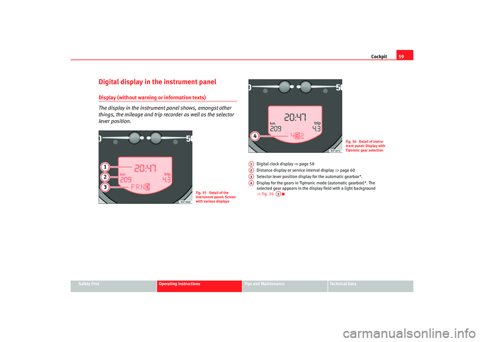
Digital display in the instrument panelDisplay (without warning or information texts)
The display in the instrument panel shows, amongst other
things, the mileage and trip recorder as well as the selector
lever position.
Digital clock display ⇒page 58
Distance display or service interval display ⇒page 60
Selector lever position display for the automatic gearbox*.
Display for the gears in Tiptronic mode (automatic gearbox)*. The
selected gear appears in the display field with a light background
⇒ fig. 36
Fig. 35 Detail of the
instrument panel: Screen
with various displays
Fig. 36 Detail of instru-
ment panel: Display with
Tiptronic gear selection
A1A2A3A4
A5
leon_ingles Seite 59 Donner stag, 24. August 2006 1:56 13
Page 62 of 292
Cockpit
60Displayed categories
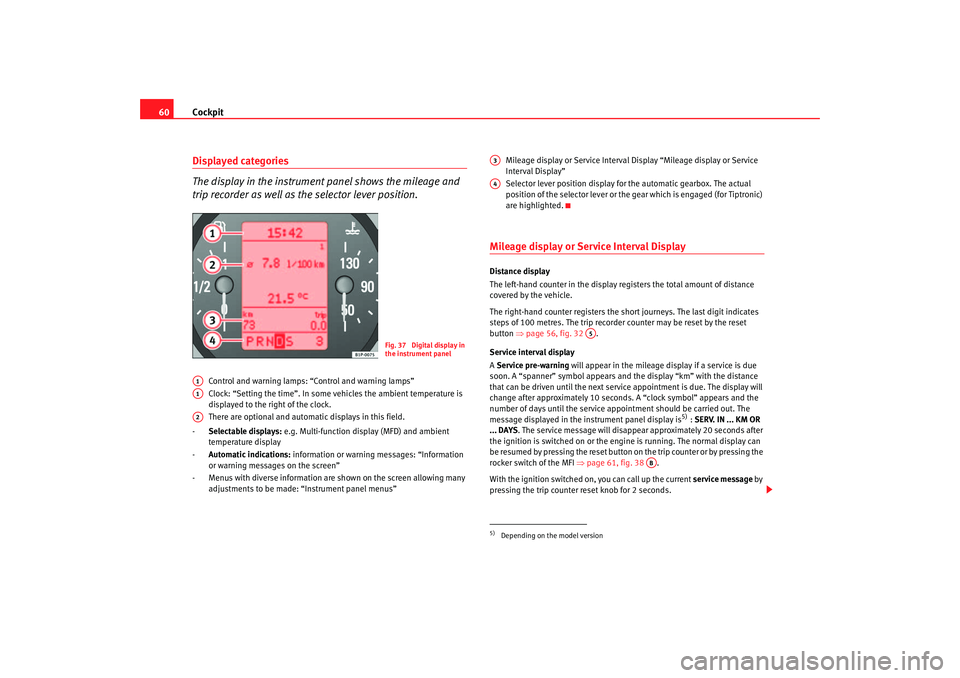
The display in the instrument panel shows the mileage and
trip recorder as well as the selector lever position.
Control and warning lamps: “Control and warning lamps”
Clock: “Setting the time”. In some vehicles the ambient temperature is
displayed to the right of the clock.
There are optional and automatic displays in this field.
- Selectable displays: e.g. Multi-function display (MFD) and ambient
temperature display
- Automatic indications: information or warning messages: “Information
or warning messages on the screen”
- Menus with diverse information are shown on the screen allowing many adjustments to be made: “Instrument panel menus” Mileage display or Service Interval Display “Mileage display or Service
Interval Display”
Selector lever position display for the automatic gearbox. The actual
position of the selector lever or the gear which is engaged (for Tiptronic)
are highlighted.
Mileage display or Service Interval DisplayDistance display
The left-hand counter in the display registers the total amount of distance
covered by the vehicle.
The right-hand counter regi
sters the short journeys. The last digit indicates
steps of 100 metres. The trip recorder counter may be reset by the reset
button ⇒page 56, fig. 32 .
Service interval display
A Service pre-warning will appear in the mileage display if a service is due
soon. A “spanner” symbol appears and the display “km” with the distance
that can be driven until the next service appointment is due. The display will
change after approximately 10 seconds. A “clock symbol” appears and the
number of days until the service appointment should be carried out. The
message displayed in the instrument panel display is
5) : SERV. IN ... KM OR
... DAYS . The service message will disappear approximately 20 seconds after
the ignition is switched on or the en gine is running. The normal display can
be resumed by pressing the reset button on the trip counter or by pressing the
rocker switch of the MFI ⇒page 61, fig. 38 .
With the ignition switched on, you can call up the current service message by
pressing the trip counter reset knob for 2 seconds.
Fig. 37 Digital display in
the instrument panel
A1A1A2
5)Depending on the model versionA3A4
A5
AB
leon_ingles Seite 60 Donner stag, 24. August 2006 1:56 13
Page 122 of 292

Lights and visibility
120Optional heated w indscreen in the wiper bl
ade* area
In some c
ou
ntries and with some versions, there is the possibility of heating
the windscreen in the area of the windscreen wiper blades in order to aid de-
icing in the zone.
This function is activated by turning the exterior heated rearview mirror*
control forwards ⇒ page 124.
WARNING
•
Worn and dirty wiper blades obstruct visibility and reduce safety levels.
•
In cold conditions, you should not use the wash / wipe system unless
you have warmed the windscreen with the heating and ventilation system.
The washer fluid could otherwise freeze on the windscreen and obscure
your view of the road.
•
Always note the corresponding warnings on ⇒page 209.Caution
In icy conditions, always check that the wiper blades are not frozen to the
glass before using the wipers for the first time. If you switch on the wipers
when the wiper blades are frozen to the windscreen, you could damage both
the wiper blades and the wiper motor.
Note
•
The windscreen wipers will only work when the ignition is switched on.
•
In vehicles fitted with alarms and in certain versions, the windscreen
wipers only operate when the ignition is on and the bonnet closed.
•
When in use, the wipers do not go as far as the rest position. When the
lever is moved to the 0 position, they move to the rest position.
•
The next speed down will automatically be selected if speed
⇒ page 119, fig. 81 or is selected when the vehicle stops. The set speed
will be resumed when the vehicle starts again.
•
The windscreen will be wiped again after approximately five seconds once
the “automatic wipe/wash system” has been operated while the vehicle is in
transit (automatic function). If the windscreen wiper function is activated
within three seconds of the automatic function, a new cleaning cycle begins
without performing the final wipe. To reactivate the “automatic” function the
ignition must be turned off and on again.
•
When the “intermittent wipe function” is on, the intervals are directly
proportional to the speed. This way, the higher the vehicle speed the shorter
the intervals.
•
The wiper will try to wipe away any obstacles that are on the windscreen.
The wiper will stop moving if the obstacle blocks its path. Remove the
obstacle and switch the wiper back on again.
•
Before removing any objects that may be trapped in the side areas of the
windscreen, always move the wiper arms to the service position
(horizontal).
A2
A3
leon_ingles Seite 120 Donnerstag, 24. August 2006 1:56 13
Page 151 of 292
Heating, Ventilation and Air conditioning 149
Safety First
Operating instructions
Tips and Maintenance
Te c h n i c a l D a t a
General notesThe pollen filter
The pollution filter (a combined pa rticulate filter and activated carbon filter)
serves as a barrier against impurities in the outside air, including dust and
pollen.
For the air conditioning system to work with maximum efficiency, the pollen
filter must be replaced at the intervals specified in the Service Schedule.
If the filter loses efficiency prematurely due to use in areas with very high
levels of air pollution, the pollen filter must be changed more frequently than
stated in the Service Schedule.
Caution
•
If you suspect that the air conditioner is damaged, switch off the air condi-
tioner with button to prevent further damage and have it checked by a
qualified workshop.
•
Repairs to the air conditioning system require specialist knowledge and
special tools. Therefore, we recommend that you take the vehicle to a quali-
fied workshop should problems occur.Note
•
If the humidity and temperature outside the vehicle are high, condensa-
tion can drip off the evaporator in the cooling system and form a pool under-
neath the vehicle, this is completely normal and there is no need to suspect
a leak.
•
Keep the air intake slots in front of the windscreen free of snow, ice and
leaves to ensure heating and cooling is not impaired, and to prevent the
windows misting over.
•
The air from the vents flows through the passenger compartment and is
extracted by slots designed for this purpose. Do not cover these slots with
articles of clothing or other objects.
•
The air conditioning system operates most effectively with the windows
and the sliding/tilting roof* closed. However, if the sun has heated up the
vehicle, the air inside can be cooled more quickly by opening the windows for
a short period.
•
Do not smoke while air recirculation mode is on, as smoke drawn into the
air conditioning system leaves a residue on the evaporator, producing a
permanent unpleasant odour.
•
The air conditioning should be turned on at least once a month, to lubri-
cate the system gaskets and prevent leaks. If a decrease in the cooling
capacity is detected, an Authorised Service Centre should be consulted to
check the system.
ECON
leon_ingles Seite 149 Donnerstag, 24. August 2006 1:56 13
Page 181 of 292
Driving and the environment179
Safety First
Operating instructions
Tips and Maintenance
Te c h n i c a l D a t a
Connectors
Your vehicle is fitted with a 12-pin co
nnector for the electrical connection
between the trailer and the vehicle.
If the trailer has a 7-pin plug you will need to use an adapter cable. This is
available from any SEAT dealer.
Trailer weight / draw bar loading
Never exceed the authorised towing limit. If you do not load the trailer up to
the maximum permitted trailer weight , you can then climb correspondingly
steeper gradients.
The maximum trailer weights listed are only applicable for altitudes up to
1,000 m above sea level. With increasing altitude the engine power and
therefore the vehicle's climbing ability are impaired because of the reduced
air density. The maximum trailer weight has to be reduced accordingly. The
weight of the vehicle and trailer co mbination must be reduced by 10% for
every further 1,000 m (or part thereof). The gross combination weight is the
actual weight of the laden vehicle plus the actual weight of the laden trailer.
Where possible, operate the trailer with the maximum permitted draw bar
weight on the ball joint of the towing bracket, but do not exceed the specified
limit.
The figures for trailer weights and draw bar weights that are given on the
data plate of the towing bracket are for certification purposes only. The
correct figures for your sp ecific model, which may be lower than these figures
for the towing bracket, are given in the registration documents ⇒Section
“Technical data”.
Distributing the load
Distribute loads in the trailer so that heavy objects are as near to the axle as
possible. Loads carried in the trailer must be secured to prevent them
moving. Tyre pressure
Set tyre pressure to the maximum permissible pressure shown on the sticker
on the inside of the fuel tank flap. Set the tyre pressure of the trailer tyres in
accordance with the trailer manufacturer's recommendations.
Exterior mirrors
Check whether you can see enough of the road behind the trailer with the
standard mirrors. If this is not the case you should have additional mirrors
fitted. Both exterior mirrors should be mounted on hinged extension
brackets. Adjust the mirrors to give sufficient vision to the rear.
WARNING
Never transport people in a trailer. This could result in fatal accidents.
Note
•
Towing a trailer places additional demands on the vehicle. We recom-
mend additional services between the normal inspection intervals if the
vehicle is used frequently for towing a trailer.
•
Find out whether special regulations apply to towing a trailer in your
country.
Ball coupling of towing bracket*Depending on the model version, the ball coupling for the towing bracket may
be found in the tool box.
The ball coupling is provided with in structions on fitting and removing the
ball coupling of the towing bracket.
leon_ingles Seite 179 Donnerstag, 24. August 2006 1:56 13
Page 189 of 292

Cleaning and caring for your vehicle187
Safety First
Operating instructions
Tips and Maintenance
Te c h n i c a l D a t a
WARNING
•
Never wash tyres with a cylindrical jet. Even at large spraying distances
and short cleaning times, visible and invisible damage can occur to the
tyres. This may cause an accident.
•
Moisture, ice and salt on the brakes may affect braking efficiency. Risk
of accident. If possible, avoid sudden braking immediately after washing
the vehicle. You must “dry” the brakes by applying the brakes carefully
several times ⇒ page 173, “Braking effect and braking distance”.
Cleaning alloy wheelsEvery two weeks
– Wash salt and brake dust from alloy wheels.
– Use an acid free detergent to clean the wheels.
Every three months
– Apply a hard wax compound to the wheels.Alloy wheels require regular attention to preserve their appearance. It is
important to remove road salt and brake dust by washing the wheels at
regular intervals, otherwise the finish will be impaired.
Always use an acid-free detergent for alloy wheels.
Car polish or other abrasive agents should not be used. If the protective
coating is damaged, e.g. by stone impact, the damaged area should be
repaired immediately.
WARNING
•
Never wash tyres with a cylindrical jet. Even at large spraying distances
and short cleaning times, visible and invisible damage can occur to the
tyres. This may cause an accident.
•
Moisture, ice and salt on the brakes may affect braking efficiency. Risk
of accident. If possible, avoid sudden braking immediately after washing
the vehicle. You must “dry” the brakes by applying the brakes carefully
several times ⇒ page 173, “Braking effect and braking distance”.
Underbody sealant
The underside of the vehicle is coated to protect it from corro-
sion and damage.The protective coating could be damage d when driving. We recommend that
the protective coating under the body and on the running gear should be
checked, and reinstated if necessary, before and after the winter season.
We recommend that repair work and addi tional anti-corrosion work is carried
out by your Authorised Service Centre.
WARNING
Do not apply underseal or anti-corros ion coatings to the exhaust pipes,
catalytic converter or the heat shield s on the exhaust system. The heat of
the exhaust system or the engine could cause them to ignite! This is a fire
hazard.
leon_ingles Seite 187 Donnerstag, 24. August 2006 1:56 13
Page 207 of 292
Checking and refilling levels205
Safety First
Operating instructions
Tips and Maintenance
Te c h n i c a l D a t a
Changing engine oil
The engine oil must be changed at the intervals given in the
service schedule.We recommend that you have the engine oil changed by an Authorised
Service Centre.
The two different oil change intervals are shown in the ⇒Booklet “Service
schedule”.
WARNING
Only change the oil yourself if you have the specialist knowledge required!•
Before opening the bonnet, read and observe the warnings
⇒ page 198, “Safety instructions on working in the engine compartment”.
•
Wait for the engine to cool down. Hot oil may cause burn injuries.
•
Wear eye protection to avoid injuries caused by splashes of oil.
•
When removing the oil drain plug with your fingers, keep your arm hori-
zontal to help prevent oil from running down your arm.
•
Wash your skin thoroughly if it comes into contact with engine oil.
•
Engine oil is poisonous! Used oil must be stored in a safe place out of
the reach of children until it is disposed of.Caution
No additives should be used with engine oil. This could result in engine
damage. Any damage caused by the use of such additives would not be
covered by the factory warranty.
For the sake of the environment
•
Because of the disposal problems, the necessary special tools and
specialist knowledge required, we recommend that you have the engine oil
and filter changed by an Authorised Service Centre.
•
Never pour oil down drains or into the ground.
•
Use a suitable container when draining the used oil. It has to be large
enough to hold all the engine oil
CoolantCoolant specifications
Coolant is a mixture of water and at least 40% coolant addi-
tive.The cooling system must be filled with a mixture of water and at least 40 % of
our coolant additive G 12+ or an addi tive with the specification TT-VW 774 F
(it is dyed purple). This mixture gives the necessary frost protection down to
-25°C and protects the alloy parts of th e cooling system against corrosion. It
also prevents scaling and raises the boiling point of the coolant.
The concentration of coolant must always be at least 40% - even if frost
protection is not required.
If greater frost protection is required in very cold climates, the proportion of
the antifreeze additive G 12+ can be increased. However, the percentage of
coolant additives should not exceed 60%, as this would reduce the frost
protection. It would also reduce th e cooling effect. A mixture with 60%
coolant additive will give frost protection to approx. -40°C.
leon_ingles Seite 205 Donnerstag, 24. August 2006 1:56 13
Page 213 of 292
Checking and refilling levels211
Safety First
Operating instructions
Tips and Maintenance
Te c h n i c a l D a t a
Brake fluidChecking the brake fluid level
The brake fluid is checked at the intervals given in the service
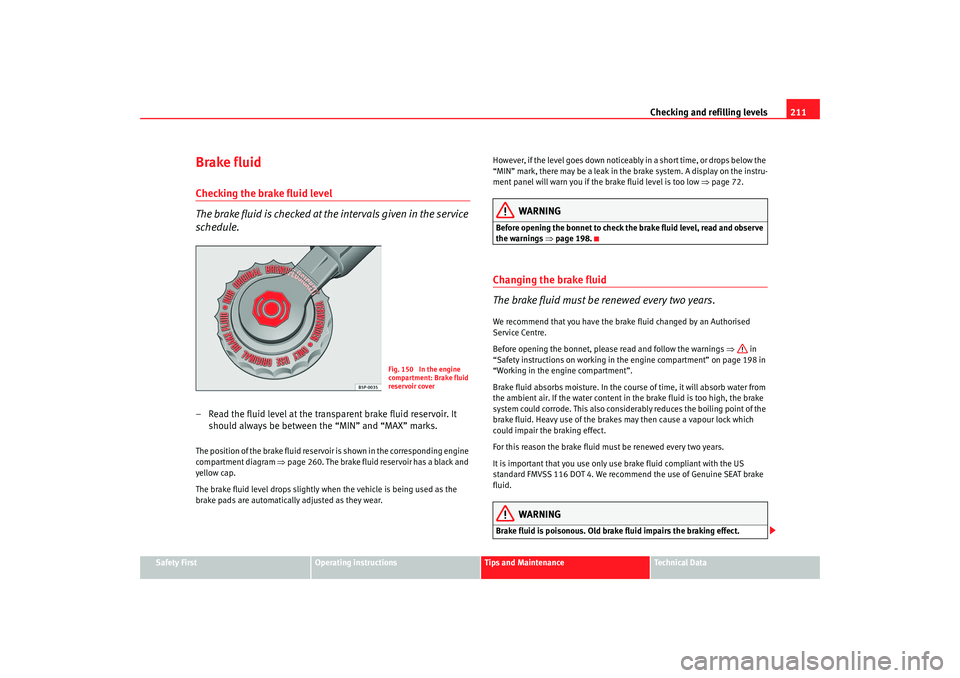
schedule.– Read the fluid level at the transparent brake fluid reservoir. It
should always be between the “MIN” and “MAX” marks.The position of the brake fluid reservoir is shown in the corresponding engine
compartment diagram ⇒page 260. The brake fluid reservoir has a black and
yellow cap.
The brake fluid level drops slightly when the vehicle is being used as the
brake pads are automatically adjusted as they wear. However, if the level goes down noticeably in a short time, or drops below the
“MIN” mark, there may be a leak in the brake system. A display on the instru-
ment panel will warn you if the brake fluid level is too low
⇒page 72.
WARNING
Before opening the bonnet to check the brake fluid level, read and observe
the warnings ⇒ page 198.Changing the brake fluid
The brake fluid must be renewed every two years.We recommend that you have the brake fluid changed by an Authorised
Service Centre.
Before opening the bonnet, please read and follow the warnings ⇒ in
“Safety instructions on working in the engine compartment” on page 198 in
“Working in the engine compartment”.
Brake fluid absorbs moisture. In the course of time, it will absorb water from
the ambient air. If the water content in the brake fluid is too high, the brake
system could corrode. This also considerably reduces the boiling point of the
brake fluid. Heavy use of the brakes may then cause a vapour lock which
could impair the braking effect.
For this reason the brake fluid must be renewed every two years.
It is important that you use only use brake fluid compliant with the US
standard FMVSS 116 DOT 4. We recommend the use of Genuine SEAT brake
fluid.
WARNING
Brake fluid is poisonous. Old brake fluid impairs the braking effect.
Fig. 150 In the engine
compartment: Brake fluid
reservoir cover
leon_ingles Seite 211 Donnerstag, 24. August 2006 1:56 13
Page 289 of 292
Index287
Seat belts . . . . . . . . . . . . . . . . . . . . . . . . . . . . . . . 19
adjustment . . . . . . . . . . . . . . . . . . . . . . . . . . . 24
Incorrectly fastened . . . . . . . . . . . . . . . . . . . . 28
Not worn . . . . . . . . . . . . . . . . . . . . . . . . . . . . . 22
Safety notes . . . . . . . . . . . . . . . . . . . . . . . . . . 23
Warning lamp . . . . . . . . . . . . . . . . . . . . . . . . . 19
Seat belts protect . . . . . . . . . . . . . . . . . . . . . . . . 23
Seat heating . . . . . . . . . . . . . . . . . . . . . . . . . . . . 130
Seats . . . . . . . . . . . . . . . . . . . . . . . . . . . . . . . . . . . 19
Selective opening* . . . . . . . . . . . . . . . . . . . . . . . 94
Selector lever locking . . . . . . . . . . . . . . . . . . . . 158
Selector lever positions . . . . . . . . . . . . . . . . . . . 157
Service interval display . . . . . . . . . . . . . . . . . . . . 60
Shoes . . . . . . . . . . . . . . . . . . . . . . . . . . . . . . . . . . 16
Side airbags . . . . . . . . . . . . . . . . . . . . . . . . . . . . . 37 Description . . . . . . . . . . . . . . . . . . . . . . . . . . . 37
Function . . . . . . . . . . . . . . . . . . . . . . . . . . . . . 39
Safety notes . . . . . . . . . . . . . . . . . . . . . . . . . . 40
Side lights . . . . . . . . . . . . . . . . . . . . . . . . . . . . . 111
Sitting position Driver . . . . . . . . . . . . . . . . . . . . . . . . . . . . . . . 10
Front passenger . . . . . . . . . . . . . . . . . . . . . . . 11
Incorrect sitting position . . . . . . . . . . . . . . . . 15
Passengers . . . . . . . . . . . . . . . . . . . . . . . . . . . 12
Sitting position, occupants . . . . . . . . . . . . . . . . . 10
Sliding/tilting roof . . . . . . . . . . . . . . . . . . . . . . . 108
Snow chains . . . . . . . . . . . . . . . . . . . . . . . 220, 259
Soot accumulation in the diesel engine particulate filter *
Indicator . . . . . . . . . . . . . . . . . . . . . . . . . . . . . 79
Spare wheel* . . . . . . . . . . . . . . . . . . . . . . . . . . . 223 Starting Petrol engines . . . . . . . . . . . . . . . . . . . 154
Starting the engine . . . . . . . . . . . . . . . . . 153, 154
After the fuel tank has been run dry . . . . . . 155
Steam cleaners . . . . . . . . . . . . . . . . . . . . . . . . . 184
Steering . . . . . . . . . . . . . . . . . . . . . . . . . . . . . . . 150 Steering lock . . . . . . . . . . . . . . . . . . . . . . . . 152
Steering wheel audio controls audio + telephone version . . . . . . . . . . . . . . 84
audio version . . . . . . . . . . . . . . . . . . . . . . . . . 84
Steering wheel controls Lighting . . . . . . . . . . . . . . . . . . . . . . . . . . . . . 92
Steering wheel height adjustment . . . . . . . . . . 150
Stowage area Other stowage areas . . . . . . . . . . . . . . . . . . 133
Stowage compartment Front passenger side . . . . . . . . . . . . . . . . . . 131
Stowage compartments Front left hand side seat . . . . . . . . . . . . . . . 132
Sun visors . . . . . . . . . . . . . . . . . . . . . . . . . . . . . 118
Sunroof . . . . . . . . . . . . . . . . . . . . . . . . . . . . . . . . 108
Sunroof blind Sliding/tilting roof . . . . . . . . . . . . . . . . . . . . 109
Switch Hazard warning lights . . . . . . . . . . . . . . . . . 114
Switches Electric windows . . . . . . . . . . . . . . . . . . . . . 106
Electrical exterior mirrors . . . . . . . . . . . . . . 124
Sliding/tilting roof . . . . . . . . . . . . . . . . . . . . 108
Switching off the engine . . . . . . . . . . . . . . . . . . 155
Switching on hazard warni ng lamps . . . . . . . . 115
TTailgate . . . . . . . . . . . . . . . . . . . . . . . . . . . . . . . 104
Emergency opening . . . . . . . . . . . . . . . . . . . 105
Warning lamp . . . . . . . . . . . . . . . . . . . . . . . . 82
Tank fuel level . . . . . . . . . . . . . . . . . . . . . . . . . . . . . 57
reserve indicator . . . . . . . . . . . . . . . . . . . . . . 57
tank capacity . . . . . . . . . . . . . . . . . . . . . . . . . 57
TCS . . . . . . . . . . . . . . . . . . . . . . . . . . . . . . . . . . . 170
TCS (Traction control system) Warning lamp . . . . . . . . . . . . . . . . . . . . . . . . 79
The danger of not using the seat belt . . . . . . . . 22
Tightening torque of wheel bo lts . . . . . . . . . . . 259
To fold down the seat back . . . . . . . . . . . . . . . . 130
Tools . . . . . . . . . . . . . . . . . . . . . . . . . . . . . . . . . . 222
Towing . . . . . . . . . . . . . . . . . . . . . . . . . . . . . . . . 251
Towing a trailer . . . . . . . . . . . . . . . . . . . . 178, 258
Towing bracket . . . . . . . . . . . . . . . . . . . . . . . . . 179
Towing bracket, fitting . . . . . . . . . . . . . . . . . . . 193
Towing eye . . . . . . . . . . . . . . . . . . . . . . . . . . . . . 251
Tow-starting . . . . . . . . . . . . . . . . . . . . . . . . . . . . 251
Traction control system warning lamp . . . . . . . . . . . . . . . . . . . . . . . . . 79
Trailer turn signals Indicator lamps . . . . . . . . . . . . . . . . . . . . . . . 76
Warning lamp . . . . . . . . . . . . . . . . . . . . . . . 116
Trailer weights . . . . . . . . . . . . . . . . . . . . . . . . . . 258
Turn signals . . . . . . . . . . . . . . . . . . . . . . . . . . . . 115 Warning lamp . . . . . . . . . . . . . . . . . . . . 76, 116
leon_ingles Seite 287 Donnerstag, 24. August 2006 1:56 13