Seat Leon 5D 2008 Workshop Manual
Manufacturer: SEAT, Model Year: 2008, Model line: Leon 5D, Model: Seat Leon 5D 2008Pages: 293, PDF Size: 8.67 MB
Page 51 of 293
Child safety
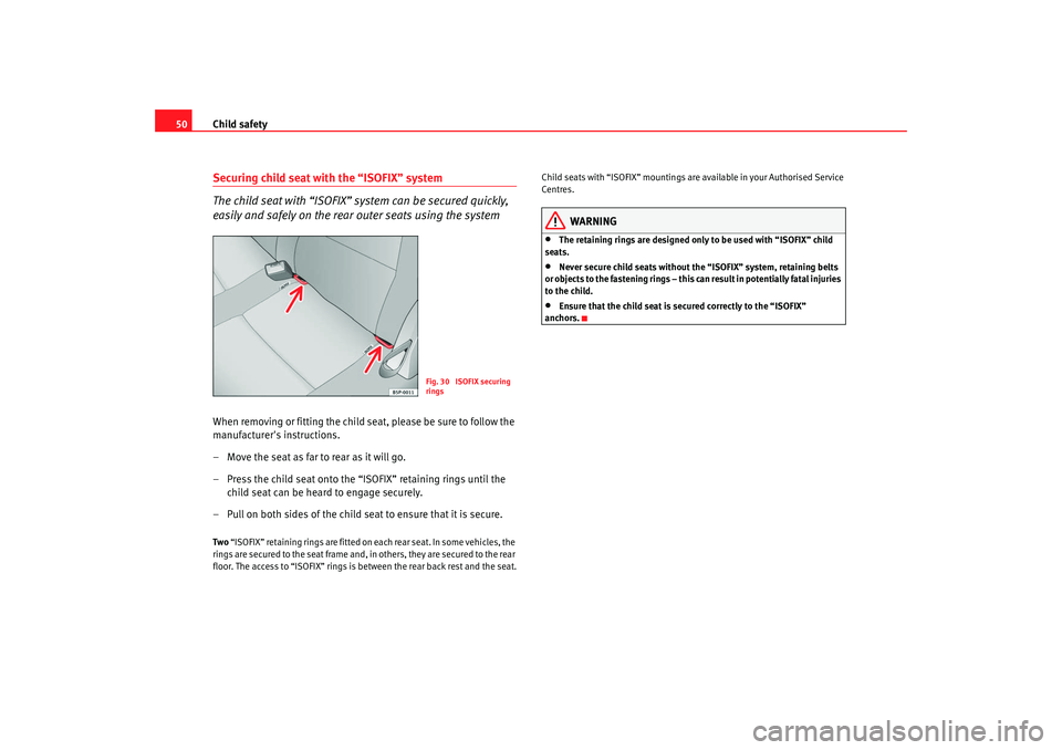
50Securing child seat with the “ISOFIX” system
The child seat with “ISOFIX” system can be secured quickly,
easily and safely on the rear outer seats using the systemWhen removing or fitting the child seat, please be sure to follow the
manufacturer's instructions.
– Move the seat as far to rear as it will go.
– Press the child seat onto the “ISOFIX” retaining rings until the
child seat can be heard to engage securely.
– Pull on both sides of the child se at to ensure that it is secure.Two “ISOFIX” retaining rings are fitted on each rear seat. In some vehicles, the
rings are secured to the seat frame and, in others, they are secured to the rear
floor. The access to “ISOFIX” rings is between the rear back rest and the seat. Child seats with “ISOFIX” mountings are available in your Authorised Service
Centres.
WARNING
•
The retaining rings are designed only to be used with “ISOFIX” child
seats.
•
Never secure child seats without the “ISOFIX” system, retaining belts
or objects to the fastening rings – this c an result in potentially fatal injuries
to the child.
•
Ensure that the child seat is secured correctly to the “ISOFIX”
anchors.
Fig. 30 ISOFIX securing
rings
leon_ingles Seite 50 Montag, 26. Januar 2009 4:29 16
Page 52 of 293
51
Safety First
Operating instructions
Practical tips
Te c h n i c a l D a t a
leon_ingles Seite 51 Montag, 26. Januar 2009 4:29 16
Page 53 of 293
52
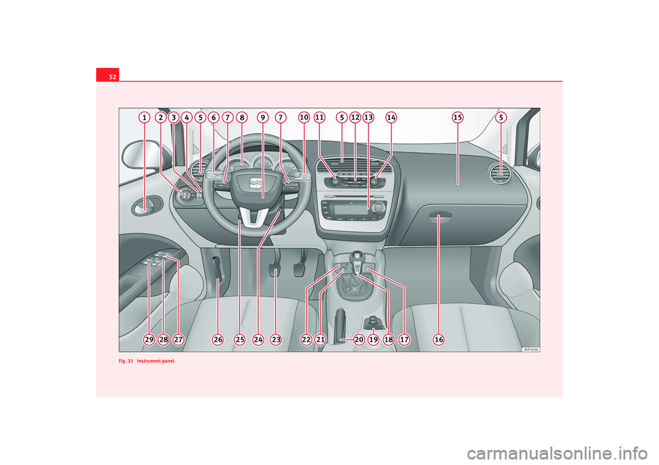
Fig. 31 Instrument panelleon_ingles Seite 52 Montag, 26. Januar 2009 4:29 16
Page 54 of 293

Cockpit53
Safety First
Operating instructions
Practical tips
Te c h n i c a l D a t a
Operating instructionsCockpitOverviewOverview of the instrument panel
This overview will help you to familiarise yourself with the
controls and displays.
Door release lever
Light switch . . . . . . . . . . . . . . . . . . . . . . . . . . . . . . . . . . . . . . . . .
Lighting control for instrument and control lighting . . . . . . . .
Headlight range control . . . . . . . . . . . . . . . . . . . . . . . . . . . . . . .
Air vent
Turn signal and main beam lever and cruise control system* .
Controls on the steering wheel . . . . . . . . . . . . . . . . . . . . . . . . .
Instrument panel:
− Instruments . . . . . . . . . . . . . . . . . . . . . . . . . . . . . . . . . . . . . . .
− Display . . . . . . . . . . . . . . . . . . . . . . . . . . . . . . . . . . . . . . . . . . .
− Indication lamps . . . . . . . . . . . . . . . . . . . . . . . . . . . . . . . . . . .
Horn (works only when the igni tion is on)/ and driver front
airbag . . . . . . . . . . . . . . . . . . . . . . . . . . . . . . . . . . . . . . . . . . . . . .
Windscreen wiper and windscreen wash lever and operation of
the multi-function display* . . . . . . . . . . . . . . . . . . . . . . . . . . . . .
Left seat heating button . . . . . . . . . . . . . . . . . . . . . . . . . . . . . . .
Controls for
− Heating* and ventilation . . . . . . . . . . . . . . . . . . . . . . . . . . . . −
Climatic* . . . . . . . . . . . . . . . . . . . . . . . . . . . . . . . . . . . . . . . . .
− Climatronic* . . . . . . . . . . . . . . . . . . . . . . . . . . . . . . . . . . . . . .
Radio/Navigator*
Right seat heating button . . . . . . . . . . . . . . . . . . . . . . . . . . . . . .
Front passenger airbag . . . . . . . . . . . . . . . . . . . . . . . . . . . . . . . .
Glove compartment lever . . . . . . . . . . . . . . . . . . . . . . . . . . . . . .
Cup holder compartment . . . . . . . . . . . . . . . . . . . . . . . . . . . . . .
Gear shift lever . . . . . . . . . . . . . . . . . . . . . . . . . . . . . . . . . . . . . .
Controls on the centre console:
− Central locking . . . . . . . . . . . . . . . . . . . . . . . . . . . . . . . . . . . .
− ESP* . . . . . . . . . . . . . . . . . . . . . . . . . . . . . . . . . . . . . . . . . . . . .
− Tyre pressure control* . . . . . . . . . . . . . . . . . . . . . . . . . . . . . .
− Park Pilot* . . . . . . . . . . . . . . . . . . . . . . . . . . . . . . . . . . . . . . . .
− Cigarette lighter / Socket . . . . . . . . . . . . . . . . . . . . . . . . . . . .
− Wing mirror adjustment . . . . . . . . . . . . . . . . . . . . . . . . . . . . .
Handbrake . . . . . . . . . . . . . . . . . . . . . . . . . . . . . . . . . . . . . . . . . .
Hazard warning light switch . . . . . . . . . . . . . . . . . . . . . . . . . . . .
Indication lamp for deactivated front passenger airbag . . . . .
Pedals
Ignition lock . . . . . . . . . . . . . . . . . . . . . . . . . . . . . . . . . . . . . . . . .
Steering column control lever* . . . . . . . . . . . . . . . . . . . . . . . . .
Handle for releasing the bonnet . . . . . . . . . . . . . . . . . . . . . . . .
Button for opening and closing the front windows . . . . . . . . .
Safety switch* for the rear windows . . . . . . . . . . . . . . . . . . . . .
Control* for opening and closing the rear windows . . . . . . . . .
A1A2
109
A3
113
A4
113
A5A6
116,170
A7
83
A8
55
58
73
A9
29
A10
119, 60
A11
131
A12
142 144
148
A13A14
131
A15
29
A16
133
A17
135
A18
161
A19
91
177
223
167
135
124
A20
165
A21
114
A22
43
A23A24
156
A25
154
A26
205
A27
104
A28
104
A29
104
leon_ingles Seite 53 Montag, 26. Januar 2009 4:29 16
Page 55 of 293
Cockpit
54
NoteSome of the items of equipment listed here are fitted only on certain
models/model years or are optional extras.
leon_ingles Seite 54 Montag, 26. Januar 2009 4:29 16
Page 56 of 293

Cockpit55
Safety First
Operating instructions
Practical tips
Te c h n i c a l D a t a
InstrumentsInstrument overview
The instruments display the vehicle operating status.Detailed view of instrument panel: instrument panel
Fuel gauge ⇒page 56
Multi-function display
Engine coolant temperature gauge ⇒page 56
Rev counter ⇒ page 57
Time adjustment button / tr ip recorder reset button ⇒page 57
Speedometer
Fig. 32 Detailed view of instrument panel: instrument
panel
A1A2A3A4A5A6
leon_ingles Seite 55 Montag, 26. Januar 2009 4:29 16
Page 57 of 293

Cockpit
56Fuel gauge
and reserve indicator
Instrument panel: fuel gauge
The fuel tank has a capacity of approx. 55 litres.
When the needle reaches the reserve zone ⇒fig. 33 (arrow), the warning
lamp will light and an acoustic signal will sound reminding the driver to
refuel. At this point there are still ab out 7 litres of fuel in the tank.
The following text appears on the instrument panel display
3) PLEASE REFUEL
[XXX] *.
Engine coolant temperature display
This gauge shows the engine coolant temperature.
Needle in cold zone
Avoid high engine speeds and heavy engine loads ⇒fig. 34 .
Needle in normal zone
In normal driving conditions, the needle should be in the middle section of
the scale. The temperature may also rise when the engine is working hard,
especially at high outside temperatures . This is no cause for concern as long
as the warning lamp does not light up and no warning* text appears in the
combi-instrument display.
Needle in warning zone
The warning lamp* ⇒page 73, fig. 47 will light up if the needle is in the
warning zone. The following warning appears on the instrument panel
3)Depending on the version of the model.
Fig. 33 Instrument panel:
fuel gauge
Fig. 34 Instrument panel:
engine coolant tempera-
ture gauge
AAABAC
A2
leon_ingles Seite 56 Montag, 26. Januar 2009 4:29 16
Page 58 of 293
Cockpit57
Safety First
Operating instructions
Practical tips
Te c h n i c a l D a t a
display
4).
Stop the car and switch off the engine. Check the coolant level
⇒ page 212 ⇒.
Even if the coolant level is correct do not continue driving. You should obtain
technical assistance.WARNING
When working in the engine compartment, always observe the safety warn-
ings ⇒page 205.
Caution
Accessories in front of the air inlet reduce the cooling effect of the coolant. At
high outside temperatures and high engine loads, there is a risk of the
engine overheating.Rev counter
The rev. counter displays the engine speed in revolutions per
minute.The start of the red zone ⇒page 55, fig. 32 indicates the maximum
engine speed operating at service temperature. However, it is advisable to
change up a into a higher gear, move the selector lever to D or lift your foot
off the accelerator before the needle reaches the red zone.
Caution
The rev counter needle must never enter the red zone on the scale. Risk of
engine damage.
For the sake of the environment
Changing up into higher gears early will help you to save fuel and minimise
engine noise.SpeedometerThe speedometer is equipped with a digital odometer and a trip counter, in
addition to a service intervals display.
During the running-in period, the instructions shown on ⇒page 182 should
be followed.Setting the digital clock*
The digital clock is located in the instrument panel display.– Turn the setting knob ⇒page 55, fig. 32 clockwise until the
first “click” to set the hour. The hour will flash. To change the
hour, press the button.
– Turn the setting knob clockwise to the second “click” to set the
minutes. The minutes will flash. To change the minutes, press the
button.
4)Depending on the version of the model.
A4
A5
leon_ingles Seite 57 Montag, 26. Januar 2009 4:29 16
Page 59 of 293
Cockpit
58Digital display in the instrument panelDisplay (without warning or information texts)
The display in the instrument panel shows, amongst other
things, the mileage and trip recorder as well as the selector
lever position.
Digital clock display ⇒page 57. On the right of the display: Selector
lever position display for the automatic gearbox*. The current position of
the selector lever or the gear which is engaged (for Tiptronic)* is high-
lighted.
Ambient temperature.
Distance display or flexible service interval display*.
Displayed categories*
The display in the instrument panel shows the mileage and
trip recorder as well as the selector lever position.
Clock: “Setting the time”. On the right of the display: Select or lever posi-
tion display for the automatic gearbox*. The current position of the
selector lever or the gear which is en gaged (for Tiptronic) is highlighted.
There are optional and automatic displays in this field.
– Optional indicators: e.g. those on the multi-function display (MFD)
– Automatic indicators: Information texts and warnings.
– Menus providing further information and which can be used to make diverse settings are also show n: “Instrument panel menus”
Ambient temperature.
Distance display or flexible service interval display.
Fig. 35 Detail of the
instrument cluster: screen
with different indicators
A1A2A3
Fig. 36 Digital display in
the instrument panel
A1A2A3A4
leon_ingles Seite 58 Montag, 26. Januar 2009 4:29 16
Page 60 of 293

Cockpit59
Safety First
Operating instructions
Practical tips
Te c h n i c a l D a t a
Recommended gear display*
This display helps to save fuel.Use the gear display to save fuel. If you are driving in the correct gear, a dot
will be shown next to the gear display. If you are not in the correct gear, an
arrow will appear next to the gear display indicating whether you should
change up or down.Mileage display or Service Interval DisplayDistance display
The left-hand counter in the display registers the total amount of distance
covered by the vehicle.
The right-hand counter registers the sh ort journeys. The last digit indicates
steps of 100 metres. The trip recorder counter may be reset by holding down
the reset button ⇒page 55, fig. 32 for a few seconds. Service interval display
A
Service pre-warning will appear in the mileage displays if a service is due
soon. A “spanner” symbol appears and the display “km” with the distance
that can be driven until the next service appointment is due. The display will
change after approximately 10 seconds. A “clock symbol” appears and the
number of days until the service appointment should be carried out. The
following message is shown in the instrument panel display: SERV. IN... KM
OR... DAYS . The service message will disappear approximately 20 seconds
after the ignition is switched on or th e engine is running. The normal display
can be resumed by pressing the reset button on the trip counter or by
pressing the rocker switch of the MFI ⇒page 60, fig. 38 .
With the ignition switched on, you can call up the current service message by
pressing the trip counter reset knob for 2 seconds.
An overdue service is indicated by a minus sign in front of the mileage or day
information.
Fig. 37 Gear display
A6
AB
leon_ingles Seite 59 Montag, 26. Januar 2009 4:29 16