turn signal Seat Leon 5D 2011 Owner's Guide
[x] Cancel search | Manufacturer: SEAT, Model Year: 2011, Model line: Leon 5D, Model: Seat Leon 5D 2011Pages: 302, PDF Size: 4.17 MB
Page 180 of 302
178Driving
Cruise speed* (Cruise control system)
Description
The cruise control system is able to maintain the set speed
in the range of 30 km/h to 180 km/h.
Once the speed setting has been saved, you may take your foot off the ac-
celerator.
WARNING
It could be dangerous to use the cruise control system if it is not possible
to drive at constant speed.
● Do not use the cruise control system when driving in dense traffic, on
roads with lots of bends or on roads with poor conditions (with ice, slip-
pery surfaces, loose grit or gravel), as this could cause an accident.
● Always switch the cruise control system off after using it in order to
avoid an involuntary use.
● It is dangerous to use a set speed which is too high for the current
road, traffic or weather conditions. Risk of accident.
Note
The cruise control cannot maintain a constant speed when descending
downhill. The vehicle will accelerate due to its own weight. Use the foot
brake to slow the vehicle. Switching the cruise control system on and off
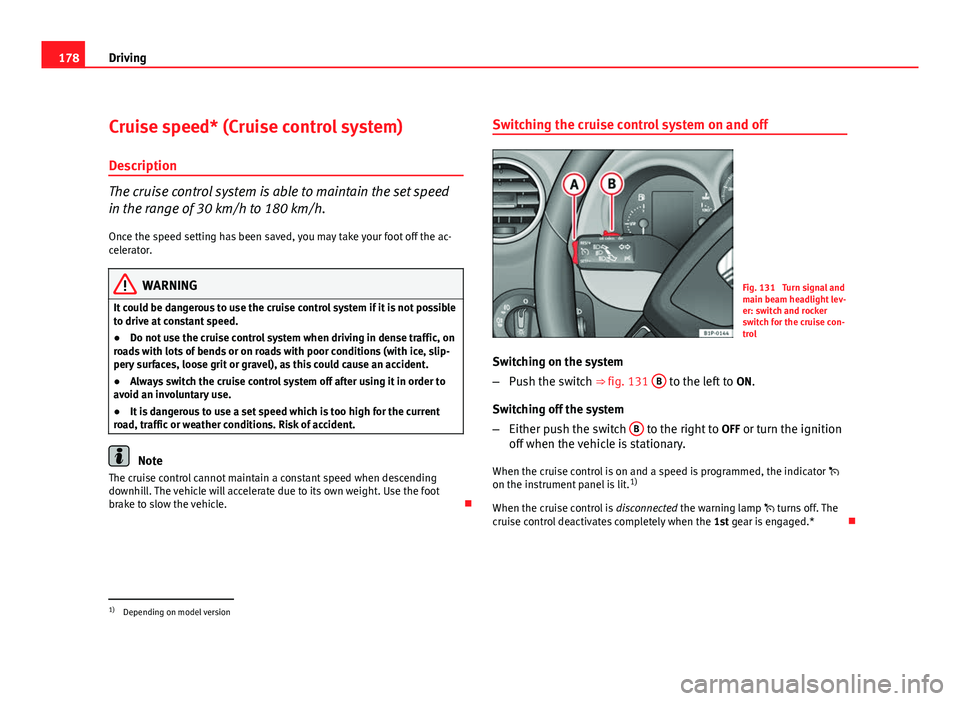
Fig. 131 Turn signal and
main beam headlight lev-
er: switch and rocker
switch for the cruise con-
trol
Switching on the system
– Push the switch ⇒ fig. 131 B
to the left to
ON.
Switching off the system
– Either push the switch B
to the right to
OFF or turn the ignition
off when the vehicle is stationary.
When the cruise control is on and a speed is programmed, the indicator
on the instrument panel is lit. 1)
When the cruise control is disconnected the warning lamp turns off. The
cruise control deactivates completely when the 1st gear is engaged.*
1)
Depending on model version
Page 181 of 302
179
Driving
Setting speed*
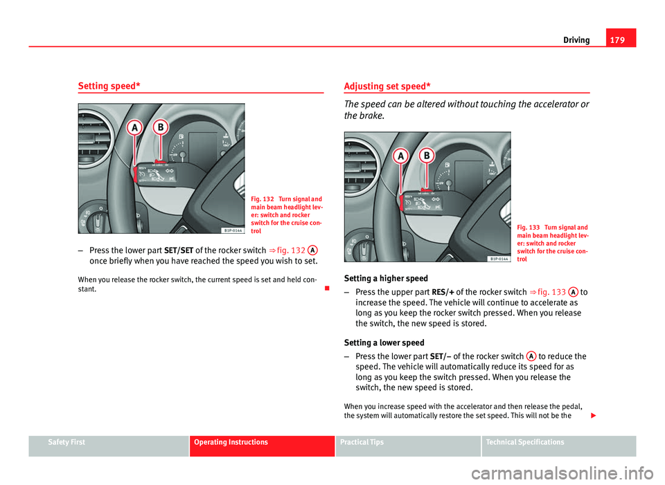
Fig. 132 Turn signal and
main beam headlight lev-
er: switch and rocker
switch for the cruise con-
trol
– Press the lower part SET/SET of the rocker switch ⇒ fig. 132 A
once briefly when you have reached the speed you wish to set.
When you release the rocker switch, the current speed is set and held con-
stant. Adjusting set speed*
The speed can be altered without touching the accelerator or
the brake.
Fig. 133 Turn signal and
main beam headlight lev-
er: switch and rocker
switch for the cruise con-
trol
Setting a higher speed
– Press the upper part RES/+ of the rocker switch ⇒ fig. 133 A
to
increase the speed. The vehicle will continue to accelerate as
long as you keep the rocker switch pressed. When you release
the switch, the new speed is stored.
Setting a lower speed
– Press the lower part SET/– of the rocker switch A
to reduce the
speed. The vehicle will automatically reduce its speed for as
long as you keep the switch pressed. When you release the
switch, the new speed is stored.
When you increase speed with the accelerator and then release the pedal,
the system will automatically restore the set speed. This will not be the
Safety FirstOperating InstructionsPractical TipsTechnical Specifications
Page 182 of 302
180Driving
case, however, if the vehicle speed is more than 10 km/h higher than the
stored speed for longer than 5 minutes. The speed will have to be stored
again.
Cruise control is switched off if you reduce speed by depressing the brake
pedal. You can reactivate the control by pressing once on the upper part of
the rocker switch RES/+ ⇒ fig. 133 A
.
WARNING
It is dangerous to use a set speed which is too high for the current road,
traffic or weather conditions. Risk of accident.
Switching off the system temporarily*
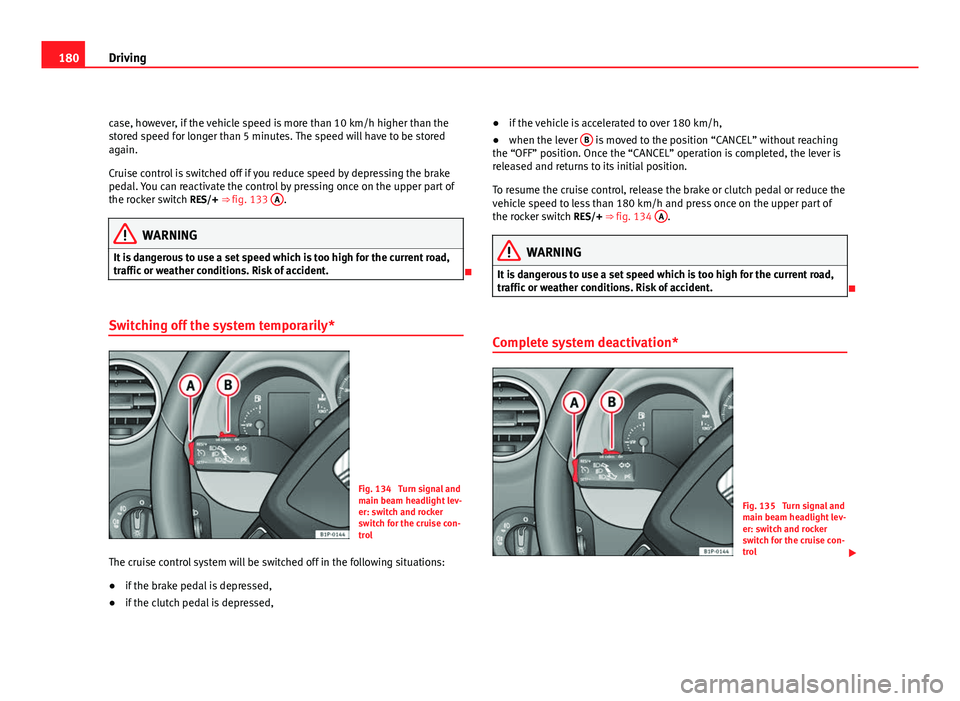
Fig. 134 Turn signal and
main beam headlight lev-
er: switch and rocker
switch for the cruise con-
trol
The cruise control system will be switched off in the following situations:
● if the brake pedal is depressed,
● if the clutch pedal is depressed, ●
if the vehicle is accelerated to over 180 km/h,
● when the lever B
is moved to the position “CANCEL” without reaching
the “OFF” position. Once the “CANCEL” operation is completed, the lever is
released and returns to its initial position.
To resume the cruise control, release the brake or clutch pedal or reduce the
vehicle speed to less than 180 km/h and press once on the upper part of
the rocker switch RES/+ ⇒ fig. 134 A
.
WARNING
It is dangerous to use a set speed which is too high for the current road,
traffic or weather conditions. Risk of accident.
Complete system deactivation*
Fig. 135 Turn signal and
main beam headlight lev-
er: switch and rocker
switch for the cruise con-
trol
Page 186 of 302
184Intelligent technology
The ASR (TCS) is connected automatically when the engine starts. If neces-
sary, it may be turned on or off pushing the button on the centre console.
When the ASR (TCS) is disconnected, the warning lamp OFF
lights up. The
TCS should normally be left on. Only in exceptional circumstances, when the
slipping of the wheels is required, should it be disconnected, for example
● With compact temporary spare wheel.
● When using the snow chains.
● When driving in deep snow or on soft terrain.
● When the vehicle is bogged-down, to free it by rocking.
The TCS should be switched on again as soon as possible.
WARNING
● Remember that the ASR (TCS) cannot defy the laws of physics. This
should be kept in mind, particularly on slippery and wet roads and when
towing a trailer.
● Always adapt your driving style to suit the condition of the roads and
the traffic situation. Do not let the extra safety afforded by ASR (TCS)
tempt you into taking any risks when driving.
CAUTION
● To ensure that the ASR (TCS) functions correctly, all four wheels must be
fitted with the same tyres. Any differences in the rolling radius of the tyres
can cause the system to reduce engine power when this is not desired.
● Modifications to the vehicle (e.g. to the engine, the brake system, run-
ning gear or any components affecting the wheels and tyres) could affect
the efficiency of the ABS and ASR (TCS). XDS*
Driveshaft differential
When taking a bend, the driveshaft differential mechanism allows the outer
wheel to turn at a higher speed than the inner wheel. In this way, the wheel
that is turning faster (outer wheel) receives less drive torque than the inner
wheel. This may mean that in certain situations the torque delivered to the
inner wheel is too high, causing the wheels to spin. On the other hand, the
outer wheel is receiving a lower drive torque than it could transmit. This
causes an overall loss of lateral grip on the front axle, resulting in under-
steer or “lengthening” of the trajectory.
By using the ESC (ESP) sensors and signals, the XDS system is able to de-
tect and correct this effect.
Through the ESC (ESP), the XDS brakes the inner wheel, thereby counteract-
ing the excess drive torque in this wheel. This means that the driver's de-
sired trajectory is much more precise,
The XDS system operates in combination with the ESC (ESP) and is always
active, even when the traction control ASR (TCS) is disconnected.
Electronic Stability Control ESC (ESP) *
General notes
The Electronic Stability Control increases the vehicle's stabil-
ity on the road. The Electronic Stability Control helps reduce the danger of skidding.
The Electronic Stability Control ESC (ESP) includes the ABS, EDL, ASR (TCS)
and Steering manoeuvre recommendations.
Page 256 of 302
254If and when
Bulb change
General notes
Before changing any bulb, first turn off the failed component.
Do not touch the bulb glass. Fingerprints vaporise in the heat, causing a re-
duction in the bulb life and condensation on the mirror surface, thus reduc-
ing efficiency.
A bulb should only be replaced by one of the same type. The type is inscri-
bed on the bulb, either on the glass part or on the base.
It is highly recommended to keep a box of spare bulbs in the vehicle. At the
very least, the following spare bulbs, which are essential for road safety,
should be kept in the vehicle.
Main headlights
● Dipped beam – H7
● Main beam – H1
● Side light – W5W
● Turn signal – PY21W Xenon headlights
1)
/adaptive*
● Dipped and main beam – D1S 2)
● DRL – P21W SLL
● Side light – W5W
● Turn signals – PY21W
Fog lights
● Fog light – HB4
Fixed tail light
● Stop/Side light – P21W 3)
or LED module 4)
● Turn signal – P21W
Mobile tailgate light
● Fog light (driver side) – P21W
● Reverse (passenger side) – P21W
● Side light – W5W or LED module 4)
Side turn signal
● Turn signal repeater – W5W
1)
On this type of headlight, the bulb changes must be made by the SEAT dealer, given that
complex elements must be removed from the vehicle and a reset must be made on the
automatic control system incorporated.
2) The Xenon bulbs discharge 2.5 times the light flux and have an average lifespan of 5 times
more than that of halogen bulbs, this means that, except due to unusual circumstances,
there is no need to change the bulbs for the whole life of the vehicle.
3) Electronically controlled single filament bulb for Stop/side bulbs. If the bulb blows it will
not work in either position or Stop.
4) Only in the LED light models. The LED modules cannot be replaced. The other lights, turn
signal light, fog light and reverse light can be replaced. If the warning lamp for the brake
light or side light (LED lights) lights up, the tail light assembly should be replaced. The fail-
ure of the lamp is only shown when the LED function goes out completely. Sometimes, a
LED will stop working, without displaying the warning as the function continues to operate.
Page 257 of 302
255
If and when
Number plate light
● Number plate light – C5W
Glove compartment lamp
● Glove compartment light – W5W
Note
● Depending on weather conditions (cold or wet), the front lights, the fog
lights, the tail lights and the turn signals may be temporarily misted. This
has no influence on the useful life of the lighting system. By switching on
the lights, the area through which the beam of light is projected will quickly
be demisted. However, the edges may continue to be misted.
● Please check at regular intervals that all lighting (especially the exterior
lighting) on your vehicle is functioning properly. This is not only in the inter-
est of your own safety, but also that of all other road users.
● Due to the difficulty in accessing some of the bulbs, any replacement
work should be done by a SEAT dealer. However, the following is a descrip-
tion of how to change the lamps except for the fog lights* and interior
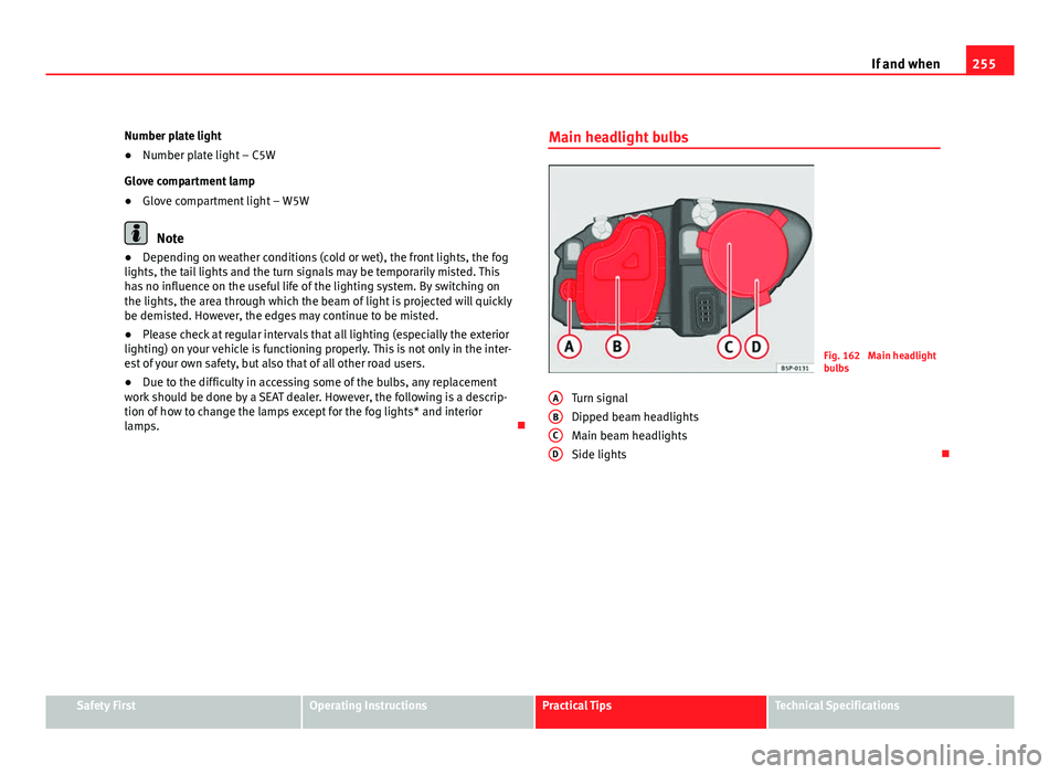
lamps. Main headlight bulbs
Fig. 162 Main headlight
bulbs
Turn signal
Dipped beam headlights
Main beam headlights
Side lights
A
BCD
Safety FirstOperating InstructionsPractical TipsTechnical Specifications
Page 258 of 302
256If and when
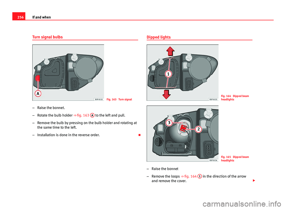
Turn signal bulbs
Fig. 163 Turn signal
– Raise the bonnet.
– Rotate the bulb holder ⇒ fig. 163 A
to the left and pull.
– Remove the bulb by pressing on the bulb holder and rotating at
the same time to the left.
– Installation is done in the reverse order. Dipped lights
Fig. 164 Dipped beam
headlights
Fig. 165 Dipped beam
headlights
– Raise the bonnet
– Remove the loops ⇒ fig. 164 1
in the direction of the arrow
and remove the cover.
Page 260 of 302
258If and when
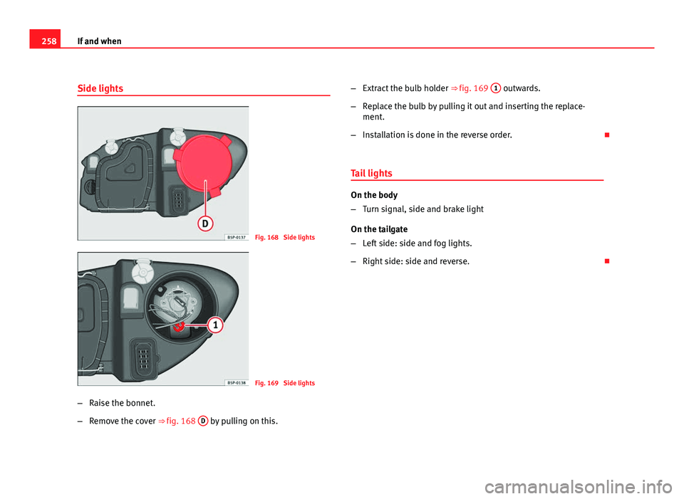
Side lights
Fig. 168 Side lights
Fig. 169 Side lights
– Raise the bonnet.
– Remove the cover ⇒ fig. 168 D
by pulling on this. –
Extract the bulb holder ⇒ fig. 169 1
outwards.
– Replace the bulb by pulling it out and inserting the replace-
ment.
– Installation is done in the reverse order.
Tail lights
On the body
– Turn signal, side and brake light
On the tailgate
– Left side: side and fog lights.
– Right side: side and reverse.
Page 261 of 302
259
If and when
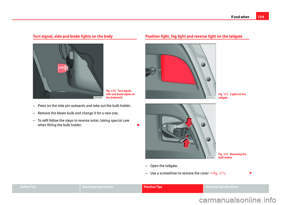
Turn signal, side and brake lights on the body
Fig. 170 Turn signal,
side and brake lights on
the bodywork
– Press on the side pin outwards and take out the bulb holder.
– Remove the blown bulb and change it for a new one.
– To refit follow the steps in reverse order, taking special care
when fitting the bulb holder. Position light, fog light and reverse light on the tailgateFig. 171 Lights on the
tailgate
Fig. 172 Removing the
bulb holder
– Open the tailgate.
– Use a screwdriver to remove the cover ⇒ fig. 171.
Safety FirstOperating InstructionsPractical TipsTechnical Specifications
Page 262 of 302
260If and when
–Take the bulbholder out pressing on the securing pins and ex-
tract it outwards ⇒ fig. 172.
– Replace the faulty bulb, rotating it to the left and outwards.
– Installation is done in the reverse order.
WARNING
If a bulb is replaced in a tail light assembly with LED, do not pull too hard
on the bulb holder. This may damage the wiring of the LED module.
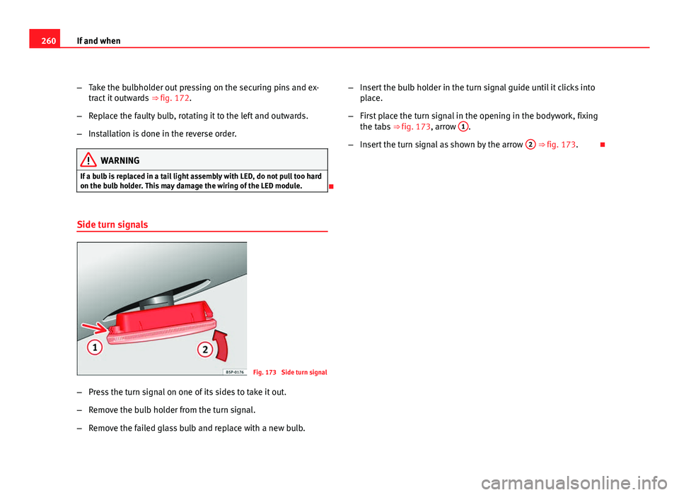
Side turn signals
Fig. 173 Side turn signal
– Press the turn signal on one of its sides to take it out.
– Remove the bulb holder from the turn signal.
– Remove the failed glass bulb and replace with a new bulb. –
Insert the bulb holder in the turn signal guide until it clicks into
place.
– First place the turn signal in the opening in the bodywork, fixing
the tabs ⇒ fig. 173, arrow 1
.
– Insert the turn signal as shown by the arrow 2
⇒ fig. 173.